 Embedded HandbookApps
173в. An open BMS on STM32: a look at Libre Solar — cell measurement, balancing, protection and SOC
Section 173б took care of a single cell: a charger IC, protection on the cell and coulomb counting in the firmware. A battery of several cells in series needs more: it has to watch every cell, bleed the fullest ones, switch the charge and discharge FETs separately and report its state over a bus. That is a BMS — a battery management system.
This section takes apart the open BMS of the Libre Solar project: what the measurement IC does, what the STM32 under Zephyr does, which thresholds are set by default, how balancing and state-of-charge estimation work. The project logic was built on a PC together with its bq769x0 driver and run through a scenario on a model of a 4S LFP battery. The run found several bugs in the driver; they are covered in 173в.7 — they show well where the delicate spots of a BMS are.
Sources: the Libre Solar BMS sources — github.com/LibreSolar/bms-firmware (commit
ee3f15a), license Apache-2.0 — below there are only short
fragments with paths. The list of boards and ICs is in boards/ and
docs/src/supported_hardware.rst. Build: gcc in the stm-sys:1 image
(the logic and the driver unchanged, plus Zephyr stubs and a model
of the IC), code sizes: arm-none-eabi-gcc in stm-arm:1; directory
_verify/bms173v. The full application was not built: Zephyr was taken at version
v4.4.2, as west.yml requires (branch v4.4), but the ThingSet libraries
(thingset-zephyr-sdk) were not part of the build. The bq769x0, BQ76952 and
ISL94202 datasheets were not used: everything about the ICs comes from the project's drivers.
License: Apache-2.0.
Terms used in the documentation
Term Meaning BMS (battery management system) the system that manages the battery AFE (analog front end), BMS IC the IC that measures and protects the battery cell balancing, bleeding equalizing cells, discharging the fullest ones through a resistor OV / UV (cell over-/undervoltage) cell overvoltage / overdischarge OCD / SCD (overcurrent / short circuit in discharge) overload / short circuit while discharging CHG / DSG FET charge switch / discharge switch reset threshold, hysteresis the level at which a fault clears, hysteresis state of charge (SOC), OCV table charge in percent, open-circuit voltage table coulomb counter (CC) coulomb counter, current integrator ThingSet an open device data protocol: read, write, publish
173в.1 The project: boards, ICs and who does what
Libre Solar BMS is Zephyr firmware for five boards. On each of them a separate IC measures and protects the battery, and the microcontroller reads it over I²C, decides which switches to turn on, computes the charge and answers over ThingSet.
Board (boards/libresolar/) |
MCU | IC | Shunt, µΩ | Board current, A |
|---|---|---|---|---|
bms_5s50_sc |
STM32F072 | bq76920 | 1000 | 50 |
bms_15s80_sc |
STM32F072 | bq76930/40 | 1500 | 80 |
bms_16s100_sc |
STM32G0B1 | BQ76952 | 300 | 100 |
bms_8s50_ic |
STM32L452 | ISL94202 | 1000 (v0.1), 500 (v0.2) | 50 |
bms_c1 |
ESP32-C3 | BQ76952 | 300 | 100 |
The ICs according to supported_hardware.rst: bq76920 — 3–5 cells, bq76930 —
6–10, bq76940 — 9–15, BQ76952 — 3–16, ISL94202 — 3–8. Each one has its own driver in
drivers/bms_ic/ behind the common bms_ic.h interface:
configure (write the thresholds), read_data (read cells, current,
temperatures, flags), set_switches (switches), balance, set_mode.
The application code (app/src/) hardly knows which IC is fitted —
the exception is in 173в.4.
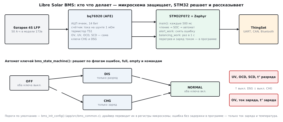
The split of work is the same as in 173б, only on a larger scale. Fast protection (cell
threshold, overload, short circuit) is in the IC: it turns the
switch off by itself, even if the program has hung. The slow part is in the program:
temperature, charge current on the bq769x0, balancing, charge in percent and
the decision when to turn the switches back on. The main loop in main.c runs every
CONFIG_BMS_IC_POLLING_INTERVAL_MS = 500 ms: read everything, update the
charge, step the state machine.
173в.2 Measurement: cells, current, temperature
Let us take the simplest driver — bq769x0 (board bms_5s50_sc).
Cells. The IC's ADC is 14-bit: the driver takes adc_raw &= 0x3FFF.
Gain and offset are individual for each IC and written at the factory; the driver
reads them at start-up from ADCGAIN1, ADCGAIN2, ADCOFFSET and converts the
code to volts: code × gain (µV) + offset (mV). Channels below 0.5 V
the driver does not treat as connected: they are not included in the average and the minimum. This is how
in the model 4 cells sit on a five-channel IC — the fifth channel
reads as 0 V.
Current comes from an integrator on the shunt; the "+" sign means charge (bms_ic.h). The conversion in
the driver:
int32_t current_mA = (int16_t)adc_raw * 8.44F / (dev_config->shunt_resistor_uohm / 1000.0F);
With a 1 mΩ shunt, one unit is 8.44 mA; anything below 10 mA in magnitude the driver sets to zero.
Temperature comes from a 10 kΩ thermistor on pin TS1, converted with the
beta formula; the default beta is 3435 (binding ti,bq769x0.yaml). In
the run the model's thermistor at 50 °C reads as 50.04 °C, at −3 °C as
−2.98 °C.
Communication with the IC. The bq769x0 comes in variants with CRC on I²C. The driver tries to write and read with CRC, and if that fails, without it. In the run the model answered with CRC: 2917 writes, not a single CRC error.
The model in the run: 4 LFP cells of 50 Ah each, internal resistance 2 mΩ, open-circuit voltage from the project's table (173в.6), beyond its edges 0.2 V per percent; ADC gain 377 µV, offset 0 mV. These are assumptions, not IC data.
173в.3 Protection: default thresholds and what the driver does with them
The thresholds are set by bms_init_config() in app/src/bms_common.c according to the cell type
(Kconfig: LFP by default, also NMC and LTO) and capacity
(CONFIG_BAT_CAPACITY_AH, 50 Ah by default):
| Cell threshold, V | LFP | NMC | LTO |
|---|---|---|---|
overvoltage cell_ov_limit |
3.80 | 4.25 | 2.85 |
charge up to cell_chg_voltage_limit |
3.55 | 4.20 | 2.80 |
reset after OV cell_ov_reset |
3.40 | 4.05 | 2.70 |
balance above bal_cell_voltage_min |
3.30 | 3.80 | 2.50 |
reset after UV cell_uv_reset |
3.10 | 3.50 | 2.10 |
discharge down to cell_dis_voltage_limit |
2.80 | 3.20 | 2.00 |
overdischarge cell_uv_limit |
2.50 | 3.00 | 1.90 |
Common to all chemistries: OV and UV delays — 2000 ms; discharge and charge current — 1C, that is 50 A at 50 Ah, delay 320 ms; short circuit — 2C, 100 A, 200 µs; discharge temperature from −20 to 45 °C, charge from 0 to 45 °C, hysteresis 5 °C. All of them can be changed over ThingSet.
The IC cannot take arbitrary numbers, so the driver rounds: the OV threshold is
the OV_TRIP code, delays and currents come from tables in bq769x0_registers.h
(OV delays 1, 2, 4, 8 s; UV 1, 4, 8, 16 s; short-circuit threshold 44…200 mV
on the shunt). In the run with a gain of 377 µV:
| What | Requested | In the IC |
|---|---|---|
| OV | 3.80 V | OV_TRIP = 0x75 → 3794 mV |
| UV | 2.50 V | UV_TRIP = 0x9F → 2503 mV |
| discharge overload | 50 A, 320 ms | 50 mV on 1 mΩ → 50 A, 320 ms |
| short circuit | 100 A, 200 µs | 89 mV → 89 A, 200 µs |
| OV delay | 2000 ms | 8 s |
| UV delay | 2000 ms | 16 s |
The last two rows are a unit error (173в.7): the delay tables are in seconds, but the driver compares them with milliseconds.
What is left to the program. The bq769x0 has only OV, UV, overload and short circuit in discharge in hardware. The charge current and all four temperature thresholds the driver checks itself on every flag read, the temperature with hysteresis: a flag, once raised, clears only 5 °C beyond the threshold. The run:
| Temperature, °C | Flags | State machine |
|---|---|---|
| 50 | 0x0280: overtemperature for charge and discharge | NORMAL → CHG → OFF |
| 42 | 0x0280 — hysteresis holds it | OFF |
| 39 | 0 | OFF → DIS → NORMAL |
| −3 | 0x0100: too cold to charge | NORMAL → DIS |
| 3 | 0x0100 — hysteresis holds it | DIS |
| 6 | 0 | DIS → NORMAL |
173в.4 The switch state machine
bms_state_machine() has four working states: OFF (both switches
off), CHG (charge only), DIS (discharge only), NORMAL (both). A step
decides on two questions: may we charge, and may we discharge.
return !bms_chg_error(bms->ic_data.error_flags & ~BMS_ERR_CHG_OFF) && !bms->full
       && bms->chg_enable;
bms_chg_error() looks at OV, charge current, charge temperatures, a broken
cell wire, IC overtemperature and cell failure; bms_dis_error() at
UV, short circuit, discharge current, discharge temperatures and the same common ones.
chg_enable and dis_enable are manual switches; over ThingSet they are
wChgEnable and wDisEnable. The full and empty flags are never set
anywhere in the application — only in the tests: the project leaves ending the charge at 3.55 V
to the charger.
One more detail for the bq769x0 and ISL94202: in the CHG state the discharge switch turns on if a discharge current above 0.5 A flows through the battery, and turns off below 0.1 A (in DIS the same happens with the charge switch). This is an "ideal diode": the current flows through the open channel, not through the body diode of the transistor.
The run: charging at 25 A from a charger that did not stop at 3.55 V, then discharge (fixed driver, 173в.7):
| Event | Time, s |
|---|---|
| start-up: OFF → DIS, then DIS → NORMAL | 0.5 and 1.0 |
| the fullest cell above 3794 mV | 496.73 |
| IC: OV, charge switch off (after 7.99 s) | 504.72 |
| state machine: NORMAL → DIS | 505.0 |
| 10 A load: cell below 3.40 V | 828.61 |
| OV cleared, DIS → NORMAL | 829.00 |
| 40 A discharge: the weakest cell below 2503 mV | 5077.96 |
| IC: UV (after 15.99 s), NORMAL → CHG | 5093.95 and 5094.0 |
| 10 A charge: the weakest above 3.10 V, CHG → NORMAL | 6188.00 |
From CHG the battery can be charged but not discharged — exactly what is needed after an overdischarge.
173в.5 Balancing
On the bq769x0, balancing is run by the driver: the balancing_work work item once a
second. The conditions from bq769x0.c: the battery has been idle longer than
bal_idle_delay (current below bal_idle_current = 0.1 A), the fullest
cell is above bal_cell_voltage_min (3.30 V for LFP), the spread is larger than
bal_cell_voltage_diff = 10 mV. Then the candidates are all cells more than 10 mV above
the minimum, in descending order of voltage; adjacent
cells in the same group of five must not be bled at the same time, and of a pair
the fuller one stays. The cell number is the bit number in CELLBAL1.
The run after charging (at rest):
| Cell | Voltage, V | Balanced |
|---|---|---|
| 1 | 3.3432 | no — neighbour of cell 2 |
| 2 | 3.3745 | yes |
| 3 | 3.3138 | no — the lowest |
| 4 | 3.7662 | yes |
CELLBAL1 = 0x0A — cells 2 and 4. Balancing started 2.29 s
after the current stopped, although the default is 1800 s (30
minutes) — this is the same unit error as with the OV and UV delays.
On the BQ76952 and ISL94202 the IC balances by itself: the drivers translate the same thresholds into its registers. The balancing current is not modelled: with resistors of tens of milliamps and cells of 50 Ah the difference takes hours to go away, and in the run what matters is which cells and when.
173в.6 Charge in percent and communication
The table. The open-circuit voltage in bms_common.c is 21 points at
5 % steps. For LFP (from the run):
| % | 100 | 95 | 90 | 80 | 70 | 60 | 50 | 40 | 30 | 20 | 10 | 5 | 0 |
|---|---|---|---|---|---|---|---|---|---|---|---|---|---|
| V | 3.392 | 3.314 | 3.309 | 3.304 | 3.283 | 3.271 | 3.265 | 3.262 | 3.240 | 3.213 | 3.177 | 3.132 | 2.833 |
For NMC it is the same 21 points from 4.198 to 2.800 V, for LTO from 2.800 to 2.000 V
(the source of the LTO table is given in the code: DOI 10.3390/batteries5010031).
The table and the capacity can be replaced over ThingSet: sOcvPoints_V,
sSocPoints_pct, sNominalCapacity_Ah.
How the project computes the charge. At start-up, once, from the table:
bms_soc_reset(&bms, -1) takes the average cell voltage. In the run
3.3105 V gave 91.53 % against a true 91.25 %. After that only coulomb
counting, bms_soc_update() after every current read: the charge accumulates in
mA·s and is moved into percent when it adds up to more than 0.1 % — at 50 Ah
that is 180000 mA·s. The table is not used again: there is no correction either at
rest or at full charge (full is never set). The project's documentation
says so directly: the charge estimate is based on coulomb counting.
Why voltage cannot be used for LFP: the table is almost flat.
| Voltage, V | 3.260 | 3.270 | 3.280 | 3.290 | 3.300 |
|---|---|---|---|---|---|
| Charge from the table, % | 39.00 | 58.33 | 68.12 | 72.69 | 77.50 |
10 mV between 3.26 and 3.27 V is 19.33 % of charge. For comparison: for the cell from 173б, 10 mV gave 2 %. In the run the model has no current sensor error, and the count held: at overdischarge 2.39 % against a true 2.00 %. Sensor offset and ageing accumulate the way shown in section 121.
Communication. All data are ThingSet objects in app/src/data_objects.c,
in four groups: Device (manufacturer, versions, xShutdown,
xReset), Conf (all thresholds from 173в.3, the table, capacity, presets
xPresetLFP, xPresetNMC, xPresetLTO), Meas (rCellVoltages_V,
rPackCurrent_A, rSOC_pct, rErrorFlags, rBmsState,
rBalancingStatus and others), Input (wChgEnable, wDisEnable). From the
flags in the code you can see the role of the first letter: r — read only, s —
read and write with saving to non-volatile memory, w — write
without saving, x — function call. Transport: serial port
(per the documentation 115200 baud, live data once a second); CAN and ISO-TP
are enabled in the .conf of boards bms_8s50_ic, bms_16s100_sc and bms_c1
(500 kbit/s in the devicetree; per the documentation the source address is the low
byte of the frame identifier); Bluetooth is on bms_c1. On bms_5s50_sc CAN is off: according to the board's .conf the F072 does not
have enough RAM. After a write to Conf, bms_ic_configure() is called —
the thresholds go to the IC immediately. The ThingSet frame format is in the
thingset-node-c library and is not covered here. For CAN as a
bus for application protocols, see section 19б.
Size of the logic on Cortex-M0 (F072) and M0+ (G0B1), arm-none-eabi-gcc -Os,
without Zephyr and ThingSet: bms_common.c — 1536 bytes of code, bms_soc.c —
272, helper.c — 252, the bq769x0 driver — 4562; 6622 bytes in total. The logic uses
168 bytes of RAM: two working tables of 21 float numbers each.
173в.7 Pitfalls
The first eight are in the bq769x0 driver of this version, and the run shows them. Whether to fix them is up to the project; here they serve as typical places where a BMS goes wrong.
After an overvoltage the battery never charges again. The error
handler clears OV when the fullest cell is below
dev_data->ic_conf.cell_ov_reset, and UV when the weakest is above
cell_uv_reset. But no function copies these two thresholds into the driver's
copy of the settings — they are zero there. OV never clears: in the
run the cell dropped below 3.40 V at 828.61 s, and at 1417.01 s the flag
was still set. UV clears immediately: under the same 40 A load, within 60 s
the IC turned the discharge switch off 4 times, the switch was on for 31.70 s, and
the cell went down to 2.3710 V at rest. With a two-line fix (the cache
receives both thresholds, fix173v.py) — one trip, 0.00 s, 2.5119 V.
Delays 4 and 8 times longer. The OV and UV delay tables are in
seconds, and cell_ov_delay_ms = 2000 is compared with them as is:
the largest is chosen — 8 s and 16 s — and 8 and
16 are written back into the _ms field. In the run OV tripped after 7.99 s, UV after 15.99 s.
Balancing after 2 s instead of 30 minutes.
if (k_uptime_get() - dev_data->active_timestamp >= dev_data->ic_conf.bal_idle_delay
— milliseconds on the left, 1800 seconds on the right. Balancing starts
bleeding cells almost immediately after the current stops, while the voltage has not
settled yet.
Thresholds in volts turn into millivolts. After writing to the
IC the driver returns the "actual" threshold:
ic_conf->cell_ov_limit = 3794, not 3.794. Over ThingSet
sCellOvervoltage_V will show 3794. Worse: any write to Conf
calls bms_ic_configure() again, and "3794 V" becomes
OV_TRIP = 0xF2 — a threshold of 4548 mV for an LFP cell, UV — 2955 mV. This is on a PC
(long is 64 bits); on Cortex-M long is 32 bits, the product overflows, and the
number will be different — not checked.
A signed ADC offset is read as unsigned.
dev_data->adc_offset = (signed int)adcoffset; — casting uint8_t to
int does not restore the sign. The driver's own code calls it "2's
complement"; with ADCOFFSET = 0xFE (−2 mV) the driver takes 254 mV, and a
cell of 3.2646 V reads as 3.5207 V. Check this on a board with a
negative offset.
After an overload the state machine is in NORMAL, but the discharge switch is off. The first
pass of the handler clears the short-circuit or overload flag immediately (the seconds
counter is 0, and 0 is divisible by 60). In the run a 150 A short for 20 ms
tripped and was cleared in the same 10 ms step, the main loop never saw the
flag, the state machine stayed in NORMAL and did not turn the switch on; a 10 A load after
that gave a current of 0.00 A. Only turning wDisEnable off and on again helped.
The same with a 60 A overload: a trip after 0.32 s, and again the switch
is off in NORMAL. There is a model assumption here: on
UV, overload and short circuit the IC turns the discharge switch off by itself, on OV the charge
switch (not checked against the datasheet). For this case the ISL94202 driver
sets the BMS_ERR_DIS_OFF and BMS_ERR_CHG_OFF flags, the bq769x0 driver does not.
Charge-current protection chatters. It is in software and has no delay
(/* ToDo: consider ic_conf->chg_oc_delay */): current 55 A → flag → charge
switch off → current 0 → flag cleared → switch on. In the run — 20 state
changes in 10 s, one every 0.5 s.
The balancing status shows zero. The balancing work item writes the
mask into ic_data->balancing_status, and every data read overwrites it with a
value that only a manual bms_ic_balance() changes. In the run, out of
1000 steps with CELLBAL1 = 0x0A, rBalancingStatus showed 0 in
510.
Nobody corrects the charge in percent. The table is used only at start-up. If the device restarted under load, the error of the starting point stays until the next start-up: on the flat part of LFP, 10 mV is worth almost 20 %.
173в.8 Summary
- Libre Solar BMS — Zephyr, Apache-2.0, five boards: STM32F072, STM32G0B1, STM32L452, ESP32-C3; ICs bq76920/30/40, BQ76952, ISL94202. The IC measures and protects fast, the MCU reads it every 500 ms, computes the charge and runs the OFF/CHG/DIS/NORMAL state machine.
- Default LFP thresholds: OV 3.80, reset 3.40, charge 3.55, discharge 2.80, reset 3.10, UV 2.50 V; current 1C (50 A) with 320 ms, short circuit 2C with 200 µs; discharge temperature −20…45, charge 0…45 °C, hysteresis 5 °C.
- In the IC the thresholds are rounded: OV 3794 mV, UV 2503 mV, short circuit 100 → 89 A; because of the units the OV and UV delays are 8 and 16 s instead of 2 s.
- Balancing: spread above 10 mV, the fullest cell above 3.30 V, at rest;
adjacent cells not together — in the run
CELLBAL1= 0x0A, but it starts after 2.29 s instead of 1800 s. - Charge: a 21-point table only at start-up (91.53 % against 91.25 %), then coulomb counting in 0.1 % steps; for LFP 10 mV is 19.33 %.
- The run found in the bq769x0 driver: OV never clears, UV clears immediately (4 trips and 31.70 s of discharge within 60 s instead of one); thresholds turn into millivolts (reconfiguration gives OV 4548 mV); offset 0xFE reads as 254 mV (+256 mV per cell); after a short circuit the switch is off in NORMAL; charge current without a delay — 20 changes in 10 s.
- The logic is 6622 bytes of code on Cortex-M0 without Zephyr and ThingSet.
Next: section 174 "Crystals, oscillators and clock circuits".