 Embedded HandbookApps
0е. Numbers for hardware: binary and hexadecimal, bits and bytes, the sign, and how to read 0x40021018
Section 0д was about electricity: a wire either carries a voltage or
it does not. This section is about the numbers that come out of that.
It is for someone who has never written a program for a microcontroller
and sees something like 0x40021018 for the first time.
There is no programming language here and no formulas. There is counting
on your fingers, a row of switches and a cabinet full of drawers. By the end
of the section 0x40021018 reads like an ordinary address, and the phrase
"set bit 2" makes sense without a single line of code. Later, on the
beginner's route (0а), the same actions are written in C.
Every number in the section is computed by a test program, and the addresses and bit numbers are taken from ST's header file for the STM32F103. The answers to the exercises in 0е.6 are checked by the same program.
Prerequisites: none. Section 0д — about the voltage on a wire — is useful, but everything here makes sense without it.
Terms used in the documentation
Term Meaning bit one binary digit, 0 or 1 byte eight bits word, half-word a word (32 bits on Cortex-M), a half-word (16 bits) binary, decimal, hexadecimal binary, decimal and hexadecimal notation nibble four bits, one hexadecimal digit LSB, MSB least significant bit (right), most significant bit (left) address the number of a memory cell register a cell that controls hardware mask a number with only the bits you need set set, clear a bit make a bit 1, make a bit 0 signed, unsigned with a sign, without a sign two's complement how negative numbers are stored
0е.1 A switch and counting on your fingers
People count in tens because they have ten fingers. Each finger is either folded or raised. But we look not at which fingers are raised, only at how many. So ten fingers show the numbers from 0 to 10.
Now let us agree on something else. Let it matter which finger is raised. The right little finger means 1, the ring finger 2, the middle finger 4, the index finger 8, the thumb 16. Each next finger is worth twice the previous one. The number is the sum of the raised fingers. One hand then shows the numbers from 0 to 31, and two hands from 0 to 1023 — 1024 different numbers in all. The same ten fingers, but more than a thousand numbers.
That is binary notation. It has only two digits: 0 (finger folded) and 1 (finger raised).
Why does hardware count this way? Inside a microcontroller there are millions of tiny switches. A switch knows only two positions: on or off. A wire either has a voltage on it (3.3 volts on the boards in this handbook) or it does not (0 volts). There is no reliable third state: noise easily turns "a little voltage" into "no" or "yes". So everything the hardware stores and sends is a long row of zeros and ones.
Decimal notation is the familiar one: ten digits from 0 to 9, and each next position to the left is worth ten times more. In 352 the three means "three hundreds", the five "five tens", the two "two ones". Binary works the same way, only each position is worth two times, not ten times, more than its right-hand neighbour.
0е.2 Bit, byte, word
A bit is one binary digit, one switch: 0 or 1. The word comes from binary digit.
One bit tells two cases apart: yes or no. Two bits give four: 00, 01, 10, 11. Each new bit doubles the number of combinations. This is the main rule of the whole section:
| Bits | Different numbers | Largest number |
|---|---|---|
| 1 | 2 | 1 |
| 4 | 16 | 15 |
| 8 | 256 | 255 |
| 16 | 65 536 | 65 535 |
| 32 | 4 294 967 296 | 4 294 967 295 |
The largest number is always one less than the count of numbers, because counting starts at zero. Eight switches have 256 positions, but if the first of them is "all off", that is 0, the last is 255.
A byte is eight bits. It is the smallest portion memory hands out under one number. One byte holds a number from 0 to 255.
A word on microcontrollers with a Cortex-M core — and STM32 are such — is 32 bits, that is four bytes. Half a word, 16 bits, is a half-word. Every register that controls an STM32 block takes up one word: 32 switches in a row, though not always all of them are used.
The bits in a row are numbered from right to left, starting at zero. The rightmost is bit 0, the least significant. In a byte the leftmost is bit 7, in a word bit 31; that is the most significant bit. The bit number matches the "finger" in 0е.1: bit 0 is worth 1, bit 1 is worth 2, bit 2 is worth 4, bit 3 is worth 8 and so on, each twice the previous.
Negative numbers. A byte has 256 combinations, and how to read them is
a matter of agreement. They can be the numbers from 0 to 255 — unsigned
numbers. Or half of them can be given to negatives, and then the same byte
holds the numbers from −128 to 127 — signed numbers. A negative number
is made like this: write the same positive number, flip all the bits
(0 to 1, 1 to 0) and add one. For −1: one is 0000 0001, flipped is
1111 1110, plus one is 1111 1111. Negative numbers always have the top
bit equal to 1, which is why it is called the sign bit. One thing matters most:
the byte itself does not know whether it is signed. The byte 1100 1000
is 200 unsigned and −56 signed. The program decides what the byte means.
More in 3а.3 and 63.14.
0е.3 Converting there and back
From binary to decimal. Write the weight of each digit above it
(from right to left: 1, 2, 4, 8, 16, …) and add up the weights where there
is a 1. For 1101:
| Position weight | 8 | 4 | 2 | 1 |
|---|---|---|---|---|
| Digit | 1 | 1 | 0 | 1 |
| Contribution | 8 | 4 | 0 | 1 |
Sum: 8 + 4 + 0 + 1 = 13. So 1101 in binary is 13.
From decimal to binary. Halve the number and write down the remainder: 0 if it divided evenly, 1 if one was left over. Keep halving until you get zero. Then read the remainders from the bottom up. For 13:
| Number | Half (whole part) | Remainder |
|---|---|---|
| 13 | 6 | 1 |
| 6 | 3 | 0 |
| 3 | 1 | 1 |
| 1 | 0 | 1 |
From the bottom up: 1101. It matches what we started with — that is how
a conversion is checked both ways.
One more example. 200 in binary is 1100 1000: 128 + 64 + 8 = 200.
Here are all the numbers that fit in four bits, in three notations. It is worth copying this table out by hand once — after that it sticks:
| Decimal | Binary | Hexadecimal |
|---|---|---|
| 0 | 0000 | 0 |
| 1 | 0001 | 1 |
| 2 | 0010 | 2 |
| 3 | 0011 | 3 |
| 4 | 0100 | 4 |
| 5 | 0101 | 5 |
| 6 | 0110 | 6 |
| 7 | 0111 | 7 |
| 8 | 1000 | 8 |
| 9 | 1001 | 9 |
| 10 | 1010 | A |
| 11 | 1011 | B |
| 12 | 1100 | C |
| 13 | 1101 | D |
| 14 | 1110 | E |
| 15 | 1111 | F |
The right-hand column is the third notation; it is the subject of the next subsection.
0е.4 Hexadecimal: four bits are one digit
Binary is honest but long. The address in the section title is 32 digits in binary:
0100 0000 0000 0010 0001 0000 0001 1000
Reading that without a mistake is hard. In decimal the same address is 1 073 877 016: short, but the number does not show which switches are on.
The way out is hexadecimal notation. It has sixteen digits: 0 to 9 and then the letters A, B, C, D, E, F, which mean 10, 11, 12, 13, 14 and 15 (the table in 0е.3). Why sixteen: that is exactly how many numbers fit in four bits. So one hexadecimal digit is exactly four bits, no more and no less. Four bits are called a nibble.
The conversion needs no arithmetic at all, only the table:
- Split the binary number into groups of four from right to left.
- Replace each group with one digit from table 0е.3.
0100 0000 0000 0010 0001 0000 0001 1000
   4    0    0    2    1    0    1    8   →  0x40021018
Back again — the same way: replace each digit with its four bits.
To keep a hexadecimal number from being mistaken for a decimal one, it is
written with 0x in front. 0x itself means nothing, it is only a label:
"hexadecimal follows". So 10 is ten and 0x10 is sixteen. Long numbers
are sometimes written with a space in the middle: 0x4002 1018 is the same
as 0x40021018.
A few more pairs to get used to: 0x2A = 0010 1010 = 42;
0xFF = 1111 1111 = 255 — a full byte, all eight switches on;
0xC8 = 1100 1000 = 200 — the number from 0е.3.
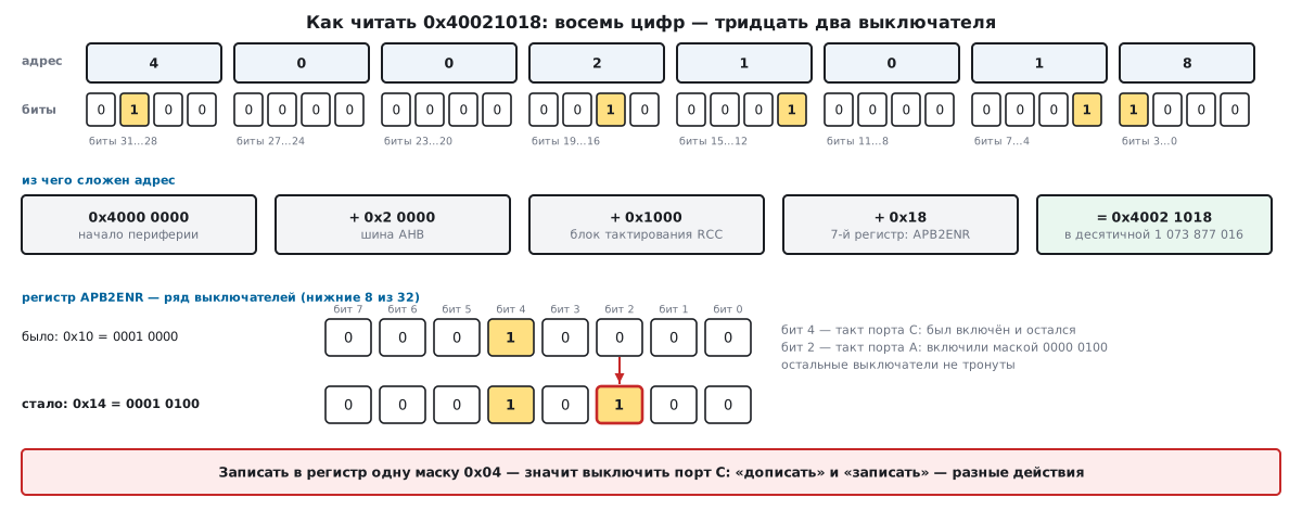
A 32-bit word is exactly eight hexadecimal digits, a byte is two. Each digit stands for its own four switches (the top row of the figure). That is why microcontroller documentation writes almost everything in hexadecimal.
0е.5 An address is a drawer number, a register is a row of switches
Address. Picture a huge cabinet of numbered drawers. Each drawer holds
one byte. The drawer number is the address. On STM32 an address is
32 bits wide, so there are 4 294 967 296 drawers: that many different
numbers fit in 32 bits (the table in 0е.2). The very first drawer is number
0x00000000, the very last 0xFFFFFFFF.
Not every drawer holds memory. The cabinet is divided into large zones:
one for the program, one for working memory, one for the peripherals —
the blocks that drive pins, timers and communication. The peripheral zone
starts at drawer 0x40000000. How the whole cabinet is divided is shown
in 1.4.
Register. Some drawers are not memory but control panels. Put a number
into such a drawer and somewhere in the microcontroller switches click:
an LED lights, a timer starts. Such a drawer is called a register.
An STM32 register is one word, 32 bits, so it takes four drawers in a row.
Hence the registers of one block are 4 apart: 0x00, 0x04, 0x08,
0x0C, 0x10, 0x14, 0x18 and so on.
How to read 0x40021018. This address is not a random number. It is built from parts, like a postal address from a city, a street and a house (the middle row of the figure):
| Part | Meaning |
|---|---|
0x40000000 |
start of the peripheral zone — the "city" |
+ 0x20000 |
the AHB bus area — the "district" |
+ 0x1000 |
the RCC clock block — the "house" |
+ 0x18 |
the APB2ENR register inside RCC — the "flat" |
= 0x40021018 |
the full address of the register |
That is exactly how this address is put together in the header file ST
supplies for the STM32F103. The offset 0x18 is 24 drawers from the start
of the RCC block: six registers of four drawers each come first, APB2ENR is
the seventh. The next register starts four drawers later, at 0x4002101C.
Adding in hexadecimal is simple here: the digits of the parts do not overlap, each sits in its own place. So the address reads in pieces, while its decimal form, 1 073 877 016, shows nothing of the kind.
What the APB2ENR register does. The name is short for "APB2 bus clock enable". Each bit is the clock switch of one block. The clock is a stream of rapid pulses without which a microcontroller block stands still, like a clock without a battery. While the bit is off, the block does not work. Bit 2 feeds the clock to pin port A, bit 4 to port C, bit 0 to the AFIO block. That too comes from ST's header file. Clocks in detail are section 6, and this very register appears in 6.5.
0е.6 "Set bit 2" without a programming language, and exercises
Suppose the clock of port C — bit 4 — is already on in APB2ENR. Then the
register holds 0x10. Its lower eight bits look like this: 0001 0000.
We need to switch on port A as well — bit 2. The bottom row of the figure
shows it step by step.
Step 1. The mask. Make a number with only the needed bit on. Bit 2 is
worth 4, so the mask is 0000 0100, that is 0x04.
Step 2. Apply the mask with the OR rule. Compare the old value and the mask bit by bit. If at least one of the two has a 1, the result gets a 1. If both have 0, it gets a 0:
было     0001 0000   (0x10)
маска    0000 0100   (0x04)
стало    0001 0100   (0x14)
Bit 2 is now on, bit 4 is as it was. The other bits are untouched.
What you must not do: simply put the mask 0x04 into the register. Then
the register holds 0000 0100 — bit 2 goes on, bit 4 goes off, and port C
stops working. "Writing" a number and "adding" a bit are different actions.
Clearing a bit is the reverse: flip the mask (1110 1111 for bit 4)
and apply it with the AND rule: the result has a 1 only where both have a 1.
0001 0100 becomes 0000 0100: port C is off, port A keeps working.
Testing a bit means looking at its place. In 0001 0100 bit 2 is 1
and bit 3 is 0.
In C each of these three actions takes one short line. How they are written is section 3а (3а.1), and why you read the old value before writing is 3а.6.
Exercises
Solve them on paper, with the table from 0е.3 in front of you.
- Convert
1011from binary to decimal. - Convert 25 to binary by halving.
- What is
0x3Cin binary and in decimal? - Write
1111 0000in hexadecimal and in decimal. - Which mask sets bit 4? Write it in hexadecimal and in decimal.
- A register holds
0x00000014. What does it become if bit 4 is cleared? - How many different numbers fit in 12 bits, and which is the largest?
- The byte
0xFEis read as a signed number. What number is it? - A register is at address
0x40021018. Where does the next one start? - The LED on the BluePill board is wired to pin 13 of port C. What is the mask of bit 13 in hexadecimal?
Answers:
- 11 (8 + 2 + 1).
11001.0011 1100, 60.0xF0, 240.0x10, 16.0x00000004.- 4096 numbers, the largest is 4095.
- −2.
0x4002101C.0x2000.
0е.7 Pitfalls
Counting bits from one. The rightmost bit is bit 0, not bit 1. "Bit 2"
is the third from the right, its mask is 0x04, not 0x02. An off-by-one
here switches on the neighbouring block instead of the right one.
Reading 0x10 as ten. 0x10 is sixteen, 0x100 is 256. Until the 0x
label becomes a habit, say it out loud: "zero-x one-zero".
Grouping the fours from the left. A binary number is split into fours
from right to left. 101010 is 10 1010, that is 0x2A; cutting from the
left gives 1010 10 and a wrong answer. Missing digits on the left are
filled with zeros: 0010 1010.
Putting the mask in instead of adding it. Writing 0x04 into a register
that held 0x10 switches port C off (0е.6). A register where every bit
controls its own block is changed with OR and AND, not by writing a bare mask.
One byte, two numbers. 1100 1000 is 200 unsigned and −56 signed.
If a sensor sent 200 and the screen shows −56, the sensor is not at fault:
the program read the byte as signed (0е.2).
Converting an address to decimal. 1 073 877 016 says nothing.
0x40021018 reads in pieces: peripherals, bus, block, register (0е.5).
0е.8 Summary
- Hardware counts in binary: a switch knows only 0 and 1. Each new bit doubles the number of combinations: 10 bits give 1024 numbers, from 0 to 1023.
- A bit is 0 or 1; a byte is 8 bits, from 0 to 255; a word on Cortex-M is 32 bits, 4 294 967 296 different numbers. Bits are numbered from the right, from zero.
- One hexadecimal digit is exactly four bits. A word is eight digits, a byte
two. The
0xlabel only means "hexadecimal":0x10= 16. - An address is the number of a drawer holding one byte. A register is a control-panel drawer four bytes wide; the registers of one block are 4 apart.
0x40021018=0x40000000+0x20000+0x1000+0x18: peripherals, the AHB bus, the RCC block, the seventh register APB2ENR. In decimal it is 1 073 877 016.- "Set bit 2" = apply the mask
0x04with OR:0x10becomes0x14. Writing the bare mask switches everything else off. - A signed byte holds −128 to 127; −1 is
1111 1111,0xFF.
Check yourself
- A register holds
0x10, and bit 2 must be turned on as well. Why not just write0x04into the register? - A)0x04is the mask of bit 4, not bit 2 - B) Only decimal numbers can be written to a register - C) You can: "write" and "add a bit" are the same thing - D) Writing the mask turns off bit 4, which was already on; the mask must be applied with OR - Why is a register address read in hexadecimal rather than in decimal? - A) The processor understands only hexadecimal numbers - B) One hex digit is exactly four bits, and the address reads in pieces: zone, bus, block, register - C) In decimal the address does not fit into 32 bits - D) Hexadecimal is just shorter; there is no other benefit
- A sensor sent a byte; the program showed −56, but 200 was expected. Where is the error? - A) The sensor is broken - B) A byte cannot hold 200 - C) The program read the byte as a signed number: the same eight bits are 200 unsigned and −56 signed - D) The bits are numbered from one, not from zero
Check yourself: answers
- 1 — D. Why: Writing a number and adding a bit are different actions: OR with the mask 0x04 gives 0x14 and leaves the other bits alone (0е.6).
- 2 — B. Why: In 0x40021018 you can see the peripherals, the bus, the RCC block and the register offset, while the decimal form of the same number shows none of that (0е.5).
- 3 — C. Why: Whether a byte is signed or not is decided by the program, not by the sensor (0е.7).
What next. This section is the step before the beginner's route 0а "Beginner's route: twenty sections in order". Here is where each idea from it leads on that route:
- 1 "The microcontroller as such" — the whole cabinet at once: the memory map (1.4);
- 3 "The C language for embedded systems" — the unsigned byte and the word in C (3.1), a register address in a program (3.3);
- 3а "Bit operations" — OR, AND and masks in one line (3а.1), why you read before you write (3а.6), the sign in shifts (3а.3);
- 6 "Clocking (RCC)" — the same APB2ENR register at work (6.5);
- 8 "Input/output ports (GPIO)" — the port registers and the LED on pin 13 (8.2, 8.4).
For more on number systems — octal, converting large numbers and two's complement with formulas — see section 63 "How text becomes a program; number systems" (63.9–63.14).
Next: section 0ж "First evening: what to buy, how to install the tools and blink an LED — step by step for someone who has never flashed a board" — the numbers are read, now to the board: purchases, two programs, four wires and the first blinker in one evening.