 Embedded HandbookApps
0ж. First evening: what to buy, how to install the tools and blink an LED — step by step for someone who has never flashed a board
Section 0е taught you to read numbers like 0x40021018. This section is about your hands.
There is no theory here, just one evening and one goal: the LED on the board blinks
under a program that you built yourself and wrote into the board yourself.
Writing a program into the board is called "flashing", and the program itself is the "firmware". You need no soldering iron and no experience. You need a board, a small adapter for flashing and four wires. After this evening the beginner's route (0а) is read with a board on the desk, not in your head.
Everything said about the project has been checked: the project was created by the same STM32CubeMX 6.18.1 you will use, built with the same options STM32CubeIDE sets, and run in an emulator — a program that pretends to be a microcontroller. There was no real board in the experiments.
Prerequisites: 0.2 — what to buy to get started; 2а — fakes; 4б — what is inside STM32CubeIDE; 8.4 — the same blinker, but without the library, on registers.
Terms used in the documentation
Term Meaning firmware the finished program for a microcontroller debug probe, ST-Link programmer-debugger: the adapter between the computer and the board SWD (Serial Wire Debug), SWDIO, SWCLK debugging over two wires: a data wire and a clock wire GPIO Output a general-purpose pin configured as an output IDE, toolchain development environment; the set of programs that builds code workspace a folder with the settings of the IDE itself Build, Run build; write into the board and start breadboard, jumper a solderless prototyping board; a jumper cap
0ж.1 What to buy
Tonight you need only the first three rows. The rest is for the next steps of the route, and it is convenient to buy it all at once, in one order.
| What | How many | Why | What to look for |
|---|---|---|---|
| BluePill board with STM32F103C8 | 1–2 | everything runs on it; the second is a spare | pin headers already soldered: otherwise you cannot do without a soldering iron |
| ST-Link V2 programmer (the "dongle") | 1 | writes the firmware into the board | any version will do: V2, V2.1, V3 (2.7) |
| female–female jumper wires | 10 | four of them go from the ST-Link to the board | sockets on both ends: the ST-Link and the board both have pins |
| breadboard | 1 | building circuits without soldering: parts plug into the holes | — |
| LEDs | 5–10 | your first own circuits | — |
| 220 Ω resistors | 10 | go in one chain with an LED and limit the current | — |
| push buttons | 2–3 | the first button in a program (8.5) | — |
Why 220 Ω. A red LED connected to a 3.3 V pin through a resistor draws a current that depends on the resistor. The calculation is in 49.3: about 0.4 V is lost in the pin, 2.0 V across the LED, and 0.9 V is left for the resistor. With 220 Ω the current comes out at 4.09 mA: the LED is clearly lit and the pin is not overloaded. With 110 Ω it is 8.18 mA, with 1 kΩ 0.90 mA: dim, but lit. How much a pin can take is in 49.7.
BluePill or BlackPill. BlackPill is a board of the same size with another chip,
STM32F411 or STM32F401 (2ж). Its LED is also on PC13 and is also lit by a zero (2ж.1),
and it can be flashed without an ST-Link, over a USB cable (2ж.4). But this whole section
is written for the BluePill: if you bought a BlackPill, choose its chip in 0ж.4; the rest
is the same.
How not to get a fake. A cheap BluePill may carry not an STM32 but a similar chip
from another maker, or a remarked one. For a blinker it almost never matters. But if the
flashing program complains about the "wrong" chip, or the board behaves oddly, open section
2а "STM32 clones and fakes: how to tell them apart". It has three cases — an original,
an honest clone under its own brand and a fake — and how to tell them apart by a program,
a debugger and by eye. For example, the debugger reads the code 0x1BA01477 from a genuine
F103, and 0x2BA01477 from a CS32F103 clone (2а.6).
0ж.2 The tools: two programs and a driver
A development environment is a set of programs in which you write, build and flash. To build means to translate the program text in C into commands the processor understands. The compiler does this: it is inside the environment, you do not install it separately.
We install two ST programs, both free:
- STM32CubeMX — sets up the pins with the mouse and creates the project;
- STM32CubeIDE — the environment: editor, compiler and flashing in one window.
The second used to include the first. Since version 2.0 they are two separate programs (4б), so we install both.
Step by step:
- On st.com find the STM32CubeMX and STM32CubeIDE pages and download the installers for your system. Both run on Windows, Linux and macOS.
- Install both programs, accepting everything offered by default.
- The ST-Link driver (Windows only). A driver is a small program that teaches Windows
to talk to a device. For the ST-Link it is the STSW-LINK009 package. If the CubeIDE
installer offers to install the ST-Link drivers, accept. If not, the package is downloaded
from ST separately under that name; it also comes with STM32CubeProgrammer
(folder
Drivers\stsw-link009_v3). Its instructions say the main thing: install it as administrator before the ST-Link is plugged into the computer. - The first start of CubeIDE asks where to keep the workspace. It is a folder with the settings of the environment itself (4б.1); accept the one offered.
- The first project in CubeMX needs the library package for the F1 series — STM32Cube FW_F1. The program offers to download it itself; you need the internet. In this section the project was created with package V1.8.7.
0ж.3 Wires: ST-Link to the board
The programmer talks to the chip over two wires — that is SWD. Two more wires are needed for power and ground. Four in total.
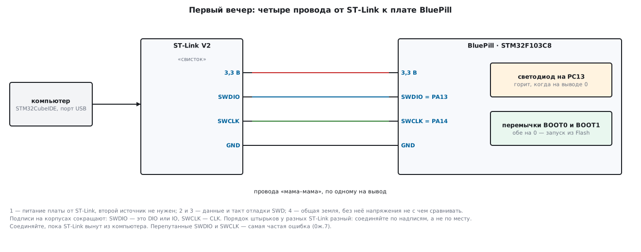
| Wire | On the ST-Link | On the board | Why |
|---|---|---|---|
| 1 | 3.3 V | 3.3 V | powers the board from the ST-Link |
| 2 | SWDIO | SWDIO, pin PA13 |
debug data |
| 3 | SWCLK | SWCLK, pin PA14 |
debug clock: the "tick-tock" by which the data is read |
| 4 | GND | GND | common ground |
Four rules, and it will work:
- Connect by the labels, not by position. Different ST-Links have their pins in a different order; the case says which is which. Labels get shortened: SWDIO is written as DIO or IO, SWCLK as CLK.
- Ground is a must. A voltage is always a difference between two points. Without a common ground the signals of the board and the ST-Link have nothing to be compared against.
- One power source. The board is powered over the 3.3 V wire from the ST-Link; the USB cable to the board itself is not needed tonight.
- BOOT0 and BOOT1 jumpers — both at 0. These are two small caps next to the reset button.
With
BOOT0= 0 the chip starts your program from Flash — memory that is not erased when power is off. WithBOOT0= 1 it starts the factory bootloader instead (4.9). This will be useful in 0ж.7.
Make the connections while the ST-Link is unplugged, and only then plug it into a USB port.
0ж.4 The first project: setting up a pin in CubeMX
A microcontroller is a small computer in one package. Its legs are called pins. A pin can be
made an input (read a button) or an output (light an LED). The BluePill LED is connected to
pin PC13: port C, pin number 13. So PC13 has to become an output.
In STM32CubeMX:
- File → New Project. In the chip selection tab (MCU/MPU Selector) type
STM32F103C8, pickSTM32F103C8Txin the list and confirm. A picture of the package with the pins around its edges appears. - The pin. Right-click pin
PC13in the picture and chooseGPIO_Output. - Debug. On the left, in the list of blocks, open
SYSand in the Debug field chooseSerial Wire. This is the most important step of the evening; why — below. - Project Manager. Project name
blink, Toolchain/IDESTM32CubeIDE. - GENERATE CODE. After generation CubeMX offers to open the project; the Open Project
button opens it in CubeIDE. If nothing opens, the project files are not associated with
CubeIDE (4б.11): then in CubeIDE use File → Import → Existing Projects into Workspace and
the
STM32CubeIDEfolder inside the project.
Leave the clock alone. By default the chip runs from its internal 8 MHz oscillator: eight million ticks per second. That is more than enough for a blinker.
Why step 3 matters so much. Without it the Debug field stays at No Debug. CubeMX takes
this literally and writes into the project a line that switches off the debug pins:
__HAL_AFIO_REMAP_SWJ_DISABLE();. The program starts, and from that second on the ST-Link
no longer sees the chip: the next flashing fails. With Serial Wire the same place holds
__HAL_AFIO_REMAP_SWJ_NOJTAG(); — SWD debugging stays on. This was checked by creating the
project twice, with Serial Wire and without; there are no other differences in the code
except this line and the clock of port A. How to bring the board back if the step was already
missed — in 0ж.7.
What CubeMX put into the project folder: Core/Src/main.c — the main file, the one we work
with; next to it five more setup files; in Drivers — the HAL library, 11 C files. HAL is
ST's library in which every action on the hardware has a clear function name.
0ж.5 Two lines of code, build and flash
Open Core/Src/main.c. The program begins with the function main — the chip starts its
work there after power-on. CubeMX has already written its beginning:
int main(void)
{
  HAL_Init();
  SystemClock_Config();
  MX_GPIO_Init();
Blank lines and comments are left out here. Three calls in order:
HAL_Init()— prepares the library and starts the millisecond clock;SystemClock_Config()— chooses the frequency: those same 8 MHz;MX_GPIO_Init()— makesPC13an output, as you set it with the mouse. First of all it writes 0 to the pin, and the BluePill LED is lit precisely by a zero: it sits between the supply and the pin (8.4). So the LED lights up even before your code.
Below is the endless loop. Add two lines to it — between the comments USER CODE BEGIN 3
and USER CODE END 3:
  /* USER CODE BEGIN WHILE */
  while (1)
  {
    /* USER CODE END WHILE */

    /* USER CODE BEGIN 3 */
    HAL_GPIO_TogglePin(GPIOC, GPIO_PIN_13);
    HAL_Delay(500);
  }
  /* USER CODE END 3 */
What each line means:
while (1)— "repeat while the condition is true". One is always true, so — forever. A microcontroller has no "exit from the program": it spins the loop while it has power./* USER CODE BEGIN 3 */and/* USER CODE END 3 */— a little fence. Everything between them CubeMX keeps if the project has to be generated again. Everything outside the fences it rewrites (4.7).HAL_GPIO_TogglePin(GPIOC, GPIO_PIN_13);— "toggle pin 13 of port C": it was 0 — it becomes 1, it was 1 — it becomes 0.GPIOCis the address of port C in the chip's memory,0x40011000.GPIO_PIN_13is the number0x2000, in which exactly one bit is set, the thirteenth: this is how the library says which of the sixteen pins is meant. How to read such numbers — in 0е.HAL_Delay(500);— wait 500 milliseconds, half a second. Inside it counts ticks — short interrupts from the built-in SysTick timer. The timer counts 8000 clock cycles, which is exactly 1 ms at 8 MHz, and reports "a millisecond has passed". The library adds one more tick to the pause for safety, so the pause is really 501 ms.- A semicolon ends each command, curly braces group commands together. That is all you need to know about C tonight; the rest is in section 3.
Build. In CubeIDE: Project → Build Project. Below, in the Console window, the compiler lines appear, and at the end — how much memory the firmware takes:
Memory region         Used Size  Region Size  %age Used
             RAM:        1584 B        20 KB      7.73%
           FLASH:        4884 B        64 KB      7.45%
FLASH is the permanent memory where the program lives: 4884 bytes out of 64 KB. RAM is the working memory for variables: 1584 bytes out of 20 KB. Almost all of it is a reserve for the stack and the heap, the program's scratch paper: 1540 bytes that the environment keeps free in advance; the real variables take 44 bytes. If your numbers differ slightly, do not worry: they depend on the compiler version.
Flash and run. Run → Run As → STM32 C/C++ Application, OK in the settings window. The
environment builds the project, writes it through the ST-Link and starts it. The very first
toggle in the loop switches off the LED lit in MX_GPIO_Init, half a second later it lights
up, after another half second it goes out — and so on while there is power.
What it looks like inside can be seen in the emulator: the calls to HAL_GPIO_TogglePin fall
on ticks 0, 501, 1002, 1503 and 2004. The step is 501 ms; a full "on — off" cycle is 1002 ms,
that is one blink per second.
0ж.6 Your first own change: blink faster
The program is your text, and you can change it. The first change is one number. Replace 500 with 100:
HAL_Delay(100);
Run → Run As → STM32 C/C++ Application again (the environment rebuilds the project itself). Now the LED blinks faster: in the emulator the toggles come on ticks 0, 101, 202, 303 and 404. The step is 101 ms, a full cycle 202 ms, which is 4.95 blinks per second, almost five. The firmware became 4 bytes shorter: 4880 instead of 4884.
Try other numbers yourself: with 1000 a full cycle is 2002 ms, one blink every two seconds;
with 50 — often. Each time check that the new number stands between USER CODE BEGIN 3 and
USER CODE END 3.
This is embedded development in miniature: change the text, build, flash, look at the hardware. Everything else in the handbook is the same cycle, only with harder tasks. The same blinker without the HAL library, by writing straight into registers, is in 8.4: after sections 1, 3 and 3а it will read as easily as these two lines.
0ж.7 Pitfalls
If flashing fails, go through the points in order: from the computer to the board. Start with the first one, even if it seems the problem is elsewhere.
1. The computer does not see the ST-Link. No driver, or a cable without data lines (there
are "charge only" cables). STM32CubeProgrammer then says No ST-Link detected!. Install the
driver (0ж.2), unplug and replug the ST-Link, try another port.
2. The ST-Link is seen, the chip is not. This is the "target not found": the environment
reports that it could not find the chip. In STM32CubeProgrammer the same trouble reads
No STM32 target found!. First of all — power: is the 3.3 V wire in place and firmly seated?
3. SWDIO and SWCLK swapped. The most common pair of mistakes (200.5). Check wires 2 and 3 against the labels on the ST-Link case and on the board.
4. No common ground. Wire 4 is missing or in the wrong place. Without ground no signal can be read (95.9).
5. The first flashing worked, the second does not. Step 3 in 0ж.4 was skipped: the project
kept No Debug, and the program switched off the debug pins. The board is not broken. Move the
BOOT0 jumper to 1 and press reset: the chip starts the factory bootloader instead of your
program, and the debug pins are free again (4.9). Set Serial Wire in CubeMX, regenerate the
project, flash it, put BOOT0 back to 0 and press reset.
6. Flashing worked, but the program does not run after reset. The BOOT0 jumper stayed at 1:
the chip starts the bootloader instead of your program every time. Put it back to 0.
7. The LED is lit steadily and does not blink. The firmware got there: MX_GPIO_Init lit
the LED. But the two lines are not in it: either the file was not saved and the project not
rebuilt, or the lines stood outside the fence and a new generation erased them. Check main.c
and build again.
8. The board answers, but as the "wrong" chip, or behaves oddly. There may be a clone or a fake on the board. That is section 2а; at the first step it tells you how to find out.
If nothing helped, section 4 has a table of ST-Link symptoms (4.5), and section 36 has the general order of troubleshooting.
0ж.8 Summary
- The first evening needs three purchases: a BluePill board, an ST-Link and female–female wires; with a 220 Ω resistor an LED on a 3.3 V pin draws 4.09 mA.
- The tools are two ST programs: STM32CubeMX sets up the pins, STM32CubeIDE builds and flashes. On Windows there is also the ST-Link driver, installed before plugging in the ST-Link itself.
- Four wires: 3.3 V, SWDIO (
PA13), SWCLK (PA14), GND. TheBOOT0andBOOT1jumpers at 0. - Two settings in CubeMX:
PC13—GPIO_Output, SYS Debug —Serial Wire. Without the second the firmware switches debugging off with the line__HAL_AFIO_REMAP_SWJ_DISABLE();. - Your own code is two lines:
HAL_GPIO_TogglePinandHAL_Delay(500). The firmware is 4884 bytes of Flash out of 64 KB and 1584 bytes of RAM out of 20 KB. HAL_Delay(500)waits 501 ticks of 1 ms: the LED blinks once per second.HAL_Delay(100)— 101 ticks and 4.95 blinks per second.- Flashing fails — the eight points of 0ж.7 in order, from the computer to the board.
Check yourself
- Why is the Debug field in the SYS block of CubeMX set to
Serial Wire? - A) Without it the firmware turns debugging off by itself, and the ST-Link stops seeing the chip - B) To make the LED blink faster - C) To enable the UART console - D) It sets the chip's clock frequency - You wrote your lines in
main.coutside theUSER CODE BEGINandUSER CODE ENDcomments. What is the risk? - A) The program will not build - B) The LED will blink slower - C) None: those comments are just decoration - D) When the project is generated again, CubeMX rewrites everything outside these fences, and the lines are lost - The
BOOT0jumper is set to 1. What does the chip start after power-on? - A) Your program from Flash - B) The factory bootloader, not your program - C) Nothing: the chip does not start - D) Your program, but without debugging
Check yourself: answers
- 1 — A. Why: Without Serial Wire CubeMX inserts the line __HAL_AFIO_REMAP_SWJ_DISABLE();, and the next flashing fails (0ж.4).
- 2 — D. Why: CubeMX keeps the code between USER CODE BEGIN and USER CODE END when it regenerates and rewrites everything outside them (0ж.5).
- 3 — B. Why: With BOOT0 = 0 the chip starts the program from Flash, with BOOT0 = 1 the factory bootloader, so on the first evening both jumpers are set to 0 (0ж.3).
What next. The board blinks — time to learn what happens inside. The beginner's route is section 0а "Beginner's route: twenty sections in order"; its stage 1 (0а.2) is five sections, and each of them can now be tried on your blinker:
- 1 "The microcontroller as such" — what a core, memory and port C are, the port you have just written to;
- 3 "The C language for embedded systems" — what
volatileand a pointer to a register are; - 3а "Bit operations" — how the number
0x2000is built and why it has one bit; - 4 "Toolchain" — what else exists besides CubeIDE, and three ways to flash a board;
- 5 "Three levels of abstraction: CMSIS, HAL and LL" — how
HAL_GPIO_TogglePindiffers from a write to a register.
At step nine of the route is section 8 "Input/output ports (GPIO)": there you will meet PC13
again, this time from the inside.
Next: section 1 "The microcontroller as such" — what lies inside the die: the core, memory, peripherals — and why without this everything that follows would have to be taken on faith.