 Embedded HandbookApps
0д. Electricity made simple: voltage, current, resistance, Ohm's law, an LED with a resistor, the multimeter and how not to burn the board
This section is for someone who has never held a soldering iron or written firmware. There are no registers and no code here. There is a battery, a bulb, a resistor, an LED and a multimeter. And there is one simple question: how to connect an LED to a board so that nothing burns out.
The beginner's route (section 0а) starts with what a microcontroller is made of and with the C language. But already at its seventh step it asks you to work out a resistor, and at the eighth to pick up a multimeter. This section prepares you for both steps. It does not replace them; it gives you the words and habits that make them easy to read.
Prerequisites: none. You need school arithmetic and a board on the desk — a BluePill with an STM32F103 will do. Every number in this section was computed by a small test bench, and the chip's limits are taken from its datasheet.
What it is called in the documentation
Original Meaning voltage the "pressure" that pushes the current current how much charge passes per second resistance how hard it is for the current to get through ground (GND) the common wire all voltages are measured from forward voltage the voltage an LED "keeps for itself" breadboard a board with holes where parts are connected without soldering absolute maximum ratings the limits beyond which the chip is damaged five-volt tolerant (FT) a pin that can take 5 volts
0д.1 Water in pipes: voltage, current, resistance
Electricity cannot be seen. So it is handy to picture it as water in pipes. The comparison is not exact, but it is enough to start with.
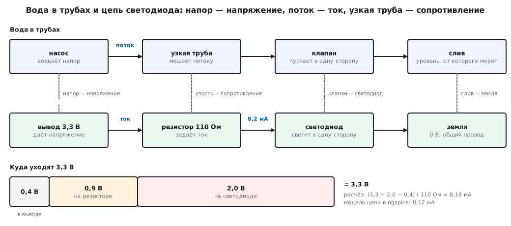
Voltage is pressure. A pump pushes on the water, and the water wants to flow. The harder the pump pushes, the higher the voltage. It is measured in volts (V). A battery is a small pump. A microcontroller board runs from 3.3 V, and a USB socket gives 5 V.
Current is flow: how much water passes through the pipe per second. It is measured in amperes (A). For a board an ampere is a lot, so people more often talk about milliamperes (mA): there are a thousand milliamperes in an ampere.
Resistance is how narrow the pipe is. A narrow pipe lets little water through, even if the pump is strong. Resistance is measured in ohms (Ω). A part that deliberately hinders the current is called a resistor.
Voltage is always measured between two points — just as pressure is measured relative to something. Current always flows in a loop: from the battery through the bulb and back to the battery. No loop, no current. A switch simply breaks that loop.
An LED is a special part. It is like a valve that lets water through in one direction only, and only when the pressure is high enough. A red LED needs about 2.0 V. While the voltage is lower, it does not light. Give it more and the current through it shoots up.
0д.2 Ohm's law in three examples
The three quantities are tied by one rule. It is called Ohm's law:
U = I · R
In words: voltage equals current multiplied by resistance. The letters come from textbooks: U is voltage in volts, I is current in amperes, R is resistance in ohms. The rule can be turned around as you like: current is voltage divided by resistance; resistance is voltage divided by current.
Example 1: find the current. A 1 kΩ resistor (a kilohm is a thousand ohms) is connected to 5 V. Divide 5 by 1000 — you get 0.005 A, that is 5 mA.
Example 2: find the voltage. 10 mA flows through a 220 Ω resistor (0.01 A). Multiply 0.01 by 220 — there are 2.2 V across the resistor.
Example 3: find the resistance. A 9 V battery must give a current of 3 mA (0.003 A). Divide 9 by 0.003 — you need a 3000 Ω resistor, that is 3 kΩ.
The main mistake in these calculations is milliamperes instead of amperes. Before dividing, convert everything into volts, amperes and ohms.
Power and heat. Current passing through a resistor heats it. How much heat is released per second is told by power, measured in watts (W):
P = U · I
In words: power equals the voltage across the part multiplied by the current through it. A 100 Ω resistor connected straight to 5 V passes 50 mA and releases 0.25 W. That is 34 times more than on the resistor in the LED circuit from the next subsection. How many watts a resistor can take is written in its datasheet. If a resistor is hot to the touch, the power was chosen wrongly.
0д.3 An LED: why it needs a resistor and how to work it out
An LED does not limit current by itself. Give it a little more than it needs, and the current grows like an avalanche. That is why a resistor is always placed in series with an LED: it takes the excess voltage and keeps the current within limits.
Working it out for a microcontroller pin (3.3 V). The pin gives 3.3 V. But the pin itself is not a perfect wire: at 8 mA it loses up to 0.4 V inside. That number is from the STM32F103 datasheet. A red LED takes 2.0 V. So the resistor is left with 3.3 − 2.0 − 0.4 = 0.9 V. We want a current of 8 mA (0.008 A):
R = (3,3 − 2,0 − 0,4) / 0,008 = 112,5
Resistors like that are not made: values come in series. The nearest in the usual series is 110 Ω. With it the current comes out at 8.18 mA.
Working it out for 5 V. The LED is powered straight from 5 V, for example from USB, without a microcontroller pin. Then the resistor is left with 5 − 2.0 = 3.0 V:
R = (5 − 2,0) / 0,008 = 375
The nearest value is 390 Ω, current 7.69 mA.
Checking with the bench. The calculation above assumes the LED takes exactly 2.0 V at any current. In reality its voltage changes slightly with current. The bench built the same circuits in the ngspice circuit simulator — with an LED model whose current depends on voltage like a real one's. Result: 8.12 mA instead of the calculated 8.18, and 7.70 mA instead of 7.69. The back-of-the-envelope calculation works.
And if you forget the resistor? The same model shows:
| Circuit | Current |
|---|---|
| 3.3 V pin → 110 Ω resistor → LED | 8.12 mA |
| 5 V rail → 390 Ω resistor → LED | 7.70 mA |
| 3.3 V pin → LED, no resistor | 18.5 to 23.4 mA |
| 5 V rail → LED, no resistor | 564 mA |
Without a resistor on a pin, the current is set by the pin itself — two to three times more than the normal 8 mA. From 5 V nothing limits the current except the LED itself: it flashes and burns out. The exact numbers without a resistor depend on the model; the conclusion is one — a resistor is always needed.
Where the power goes in the pin circuit: the resistor heats up by 7.4 mW, the LED by 16 mW, the pin itself by 3.3 mW. Together 27 mW — that is little, any small resistor will cope. In the 5 V circuit the resistor releases 23 mW — also not much.
0д.4 Ground, the common wire and the breadboard
Ground is the point all voltages are measured from. It is taken as zero. In the water picture it is the drain level: the pump's pressure is measured relative to it. On a board the ground pins are labelled GND. When people say "3.3 V on a pin", they mean 3.3 V between that pin and ground.
Hence the first rule: two devices that exchange signals have their grounds connected. A board and a USB adapter to the computer, a board and a sensor, a board and a power supply — always a common ground wire. Without it the signal voltage simply has nothing to be counted from, and the data do not get through.
A breadboard is a board with holes where parts are pushed in without soldering. Under the holes there are hidden metal strips. Holes on one strip are connected to each other, holes on different strips are not. The usual layout:
- in the middle — short rows of holes across the board; a groove runs down the middle, and the left row is not connected to the right one — a chip is placed over the groove so that its legs are not shorted together;
- along the edges — long lines along the board, marked "+" and "−": power and ground go there.
Breadboards differ: for example, a long power line is sometimes broken in the middle. So do not take it on trust — check with a multimeter in continuity mode (0д.5): two holes are connected if the meter beeps.
0д.5 The multimeter: voltage, current, continuity
The multimeter is the first instrument on the desk. It has a mode switch and several sockets for the probes. The black probe always goes into the COM socket — the meter's ground. The red one goes into the voltage socket, and for current — into a separate socket labelled A or mA.
Voltage is measured without breaking anything. The mode is DC voltage (the V symbol with a straight line). The black probe goes to the board's ground, the red one to the point being checked. The meter stands beside the circuit, like a pressure gauge on a pipe. Mix up the probes and you see a number with a minus sign; that is not dangerous.
Current is measured in a break. The circuit is broken, and the current is passed through the meter itself: it goes in line, like a water meter in a pipe. The red probe is moved to the current socket. Inside the meter in this mode there is almost a wire: a small resistance the meter uses to judge the current.
Continuity — is there a connection. The meter beeps if there is almost no resistance between the probes. Only a switched-off board is tested this way: has a trace made it, are two breadboard holes connected, is the supply shorted to ground.
What not to do.
⚠️ An ammeter is never placed in parallel. A meter in current mode is almost a wire. Touch two points that carry a voltage with it, as when measuring volts, and you get a short circuit. Say there are 5 Ω inside the meter — then 1 A flows from 5 V, and 5 W is released in the meter. The meter's fuse blows, or even the board.
- Do not measure resistance or test continuity on a powered board.
- After measuring current, put the red probe back into the voltage socket. Otherwise the next "voltage measurement" becomes that very short circuit.
0д.6 3.3 V versus 5 V: why a pin is not a power source
The STM32F103 lives on 3.3 V. Its datasheet gives the limits right in the tables on pages 37, 38 and 65:
| What | Limit |
|---|---|
| chip supply | 2 to 3.6 V |
| supply above which it is damaged | 4.0 V |
| current of one pin, normal mode | 8 mA |
| current of one pin, with relaxed levels | 20 mA |
| current of one pin, absolute limit | 25 mA |
| pins PC13, PC14, PC15 | 3 mA |
| all pins and the chip itself together | 150 mA |
| loss in the pin at 8 mA | 0.4 V |
| loss in the pin at 20 mA | 1.3 V |
Three conclusions from the table.
Five volts on the supply — no. The limit is 4.0 V. Five volts from USB go to the input of a regulator, and it gives the chip 3.3 V.
Five volts on a pin — only on some. Pins marked FT take up to 5.5 V. The rest take no more than the supply plus 0.3 V, that is 3.6 V. On the BluePill 20 of its 34 input/output pins are like that. For example, PA9 and PA10 are FT, and PA0 is not. A 5 V sensor connected to a pin without FT can damage it.
A pin is a signal, not a power source. It is meant for an LED, not a motor. The relay coil from section 52 consumes 360 mW; from 5 V that is 72 mA — almost three times the pin's absolute limit. A small motor, a relay, an LED strip are switched through a transistor: the pin only gives the command, and the current comes from a separate supply.
One more thing: the LED on the BluePill itself hangs on PC13, and that pin gives only 3 mA. Do not connect anything of your own to it.
0д.7 Pitfalls
The LED does not light at all. It passes current in one direction only — turn it around. On a new LED the long leg is plus (the anode). Another cause is a break in the circuit: no loop, no current. Check with continuity mode.
The LED flashed brightly and went out for good. It was switched on without a resistor. From 5 V the model gives 564 mA — the LED burned out. A resistor is always needed.
The LED on a pin is dim, the chip is warm. The pin carries too much current: at 20 mA the pin already loses 1.3 V instead of 0.4. Take a larger resistor or switch the load through a transistor.
The multimeter stopped showing current, or something smells burnt. The ammeter was placed in parallel — the meter's fuse has blown. Current is measured only in a break.
The board and the adapter are connected, but no data get through. There is no common ground. Connect GND to GND.
Half the breadboard has no power. The long power line is broken in the middle. Check with continuity mode and fit a jumper.
After a 5 V sensor the pin stopped working. 5 V was applied to a pin without the FT mark. Such pins take no more than 3.6 V.
0д.8 Summary
- Voltage is pressure, current is flow, resistance is how narrow the pipe is. Current flows only in a loop; voltage is measured between two points.
- Ohm's law: voltage = current × resistance. Three examples: 5 V across 1 kΩ — 5 mA; 10 mA through 220 Ω — 2.2 V; 9 V and 3 mA — 3 kΩ.
- Power = voltage × current. A 100 Ω resistor on 5 V heats up by 0.25 W — 34 times more than the resistor in the LED circuit.
- An LED needs a resistor. From a 3.3 V pin — 110 Ω and 8.18 mA, from 5 V — 390 Ω and 7.69 mA; the circuit model gave 8.12 and 7.70 mA.
- Ground is the zero everything is measured from. Devices that talk to each other have their grounds connected.
- Multimeter: voltage — beside the circuit, current — in a break, continuity — only without power. An ammeter in parallel is a short circuit.
- STM32F103: supply 2 to 3.6 V, a pin — 8 mA in normal mode, 25 mA limit, 150 mA for everything. 5 V only on FT pins; the BluePill has 20 of 34.
Check yourself
- Why is a resistor placed in series with an LED? - A) To make the LED brighter - B) The LED does not limit current by itself: the resistor takes the extra voltage and keeps the current normal - C) To let the LED conduct in both directions - D) The resistor is needed only from 5 V; from a 3.3 V pin you can do without it
- A multimeter in current mode is touched to two points with voltage between them, as when measuring volts. What happens? - A) The meter shows the voltage between the points - B) The meter shows the current flowing in the circuit - C) A short circuit: in current mode the meter is almost a wire - D) Nothing: in current mode the probes are disconnected
- Why is a relay or a small motor not connected straight to a microcontroller pin? - A) A pin is a signal, not a power source: the load is switched by a transistor, and the current comes from a separate supply - B) A pin gives AC voltage, while a relay needs DC - C) A relay works only from USB - D) You can connect it directly if you add a bigger resistor
Check yourself: answers - 1 — B. Why: Give an LED a little more voltage than it needs and the current grows like an avalanche, so the resistor is always needed (0д.3). - 2 — C. Why: Current is measured only in a break of the circuit; an ammeter in parallel shorts the points and blows the meter's fuse, or even the board (0д.5). - 3 — A. Why: A pin is made for an LED, not for a motor: it only commands the switch (0д.6).
What next. Now you can follow the beginner's route (0а.1). Its first steps are reading (0а.2): section 1 "The microcontroller as such", section 3 "The C language for embedded systems", section 3а "Bit operations" and section 4 "Toolchain". Then comes the stage with the board (0а.3), and everything from this section comes in handy there:
- step 7 — section 49 "Voltage, current, power: Ohm's law and first calculations": the same resistor for an LED (49.3), but with part tolerances, and what a pin can do (49.7);
- step 8 — section 36а "Instruments on the bench: multimeter, oscilloscope, logic analyzer": the multimeter in detail (36а.1) and a power supply that limits the current by itself (36а.8);
- step 9 — section 8 "Input/output ports (GPIO)": the first LED from your own program (8.4).
Stuck on the route — see the table of trouble spots (0а.6).
Next: section 0е "Numbers for hardware: binary and hexadecimal, bits and bytes, the sign, and how to read 0x40021018" — after volts and the zero on a wire: how switches turn into numbers, what a bit and a byte are, and how to read a register address without a single line of code.