 Embedded HandbookApps
93а. nRF24L01: a 2.4 GHz radio over SPI — addresses, channels, Enhanced ShockBurst, acknowledgements and retransmits
Section 93 is about the LoRa radio: far, slow, with a link budget calculation. Here is its opposite: the cheapest 2.4 GHz module, which reaches tens of metres but is fast, and acknowledges and retransmits packets on its own. The microcontroller is left with SPI, two pins and an interrupt. We look at what goes on air, how to connect the module to the F103, which commands and registers are needed, how acknowledgements, retransmits and the six receive pipes work, and where people usually lose an evening with this module.
Sources: RM0008 (DocID13902 Rev 17): the pin mode table, p. 160;
AFIO_EXTICR1, p. 190; EXTI_FTSR, p. 211; the BR divider in
SPI_CR1, p. 743; CPOL and CPHA, p. 744. DocID13587 Rev 17
(STM32F103x8/xB): PA4–PA7 are SPI1_NSS, SPI1_SCK, SPI1_MISO,
SPI1_MOSI, p. 29. The project has no document on the nRF24L01+: the
commands, registers, reset values, packet format and CRC come from the
well-known specification and are built into the model. So everything
below checks that the driver agrees with the model, not with the chip.
All numbers come from a run of the driver _verify/nrf93b/nrf93b.c on a
computer (gcc 12.2.0) with our own model of the modules and the air in
Python 3.11; the firmware is built by armclang 6.24 for the Cortex-M3.
What it is called in the documentation
Original Meaning Enhanced ShockBurst (ESB) the module's packet protocol with acknowledgement and retransmit PTX / PRX transmitter / receiver data pipe receive pipe: its own address, up to six per receiver auto acknowledgement automatic acknowledgement auto retransmit delay (ARD) / count (ARC) wait for the acknowledgement / number of retransmits packet control field (PCF) packet control field: length, PID, NO_ACK packet identity (PID) packet number, 2 bits: to spot a retransmit dynamic payload length (DPL) variable packet length payload user data chip enable (CE) pin that enables receive and transmit flush empty a FIFO GFSK frequency shift keying with a Gaussian filter
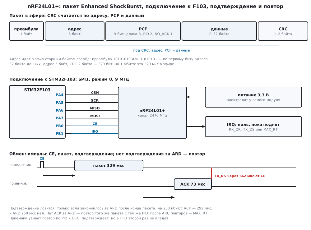
93а.1 What the module is
The nRF24L01+ is a 2.4 GHz transceiver with SPI. The modulation is GFSK,
the rates are 250 kbit/s, 1 and 2 Mbit/s, and the channel is set by the
RF_CH register: the frequency is 2400 + RF_CH MHz, channels 0–125 in
1 MHz steps. These numbers come from the well-known specification; the
project has no document on the module. The driver of this section sets
channel 76: the model converted it to 2476 MHz.
The main difference from "just a radio" is Enhanced ShockBurst: the
module itself builds, acknowledges and retransmits the packets. The
transmitter puts the data into the FIFO and pulses CE; the module sends
the packet, switches to receive and waits for the acknowledgement. No
acknowledgement — it retransmits by itself, up to ARC times. The
receiver, also without the program, checks the CRC, replies with an
acknowledgement and stores the packet in a FIFO of three packets. The
program gets a single flag: sent, not sent or received.
Hence the layout of the section: SPI and registers in 93а.3, the packet in 93а.4, acknowledgements and retransmits in 93а.5, receive and pipes in 93а.6.
93а.2 Connection to the F103
The connection is the same as for the SX1276 in section 93.5 — SPI1 and two pins:
| Module pin | STM32 | Purpose |
|---|---|---|
| CSN | PA4 | select, active low; start and end of every command |
| SCK | PA5 | SPI1 clock |
| MISO | PA6 | data from the module |
| MOSI | PA7 | data to the module |
| CE | PB0 | "1" — listen (receiver), a pulse — transmit |
| IRQ | PB1 | low while a flag is set; EXTI1 on the falling edge |
| VCC, GND | — | 3.3 V only |
PA4–PA7 are the SPI1 pins (DocID13587, p. 29). CSN is a plain output
here: it must stay low for the whole command, from the first byte to the
last. SPI is mode 0 (CPOL = 0, CPHA = 0, p. 744), most significant
bit first. APB2 at 72 MHz, divider 8 (BR = 010, p. 743) — 9 MHz; the
module's SPI limit in the well-known specification is 10 MHz. PB1 is an
input with pull-up (code 1000 in the pin mode table, p. 160),
AFIO_EXTICR1 = 0001 selects it for EXTI1 (p. 190), and EXTI_FTSR
enables the falling edge (p. 211):
static void spi1_init(void)
{
    RCC->APB2ENR |= RCC_APB2ENR_IOPAEN | RCC_APB2ENR_IOPBEN | RCC_APB2ENR_IOPCEN | RCC_APB2ENR_AFIOEN
                  | RCC_APB2ENR_SPI1EN;
    /* PA7, PA5 — альтернативная функция 50 МГц (1011), PA6 — вход (0100), PA4 — выход 50 МГц (0011) */
    GPIOA->CRL = (GPIOA->CRL & 0x0000FFFFu) | 0xB4B30000u;
    GPIOA->BSRR = 1u << 4;                              /* CSN = 1 до первой команды */
    /* PB0 — выход (0011), PB1 — вход с подтяжкой (1000) */
    GPIOB->CRL = (GPIOB->CRL & 0xFFFFFF00u) | 0x00000083u;
    GPIOB->BSRR = 1u << 1;                              /* подтяжка PB1 вверх; CE = 0 */
    GPIOB->BSRR = 1u << 16;
    /* PB10 — вход с подтяжкой: перемычка на землю — приёмник */
    GPIOB->CRH = (GPIOB->CRH & ~(0xFu << 8)) | 0x8u << 8;
    GPIOB->BSRR = 1u << 10;
    GPIOC->CRH = (GPIOC->CRH & ~(0xFu << 20)) | 0x2u << 20;    /* PC13 — светодиод */
    /* APB2 72 МГц / 8 = 9 МГц, режим 0, старший бит первым */
    SPI1->CR1 = SPI_CR1_MSTR | SPI_CR1_BR_1 | SPI_CR1_SSM | SPI_CR1_SSI | SPI_CR1_SPE;
}
Power. The module runs from 3.3 V. When transmitting it draws current in bursts, and the wires and the weak regulator of the BluePill sag — an electrolytic capacitor goes right at the module, usually 10–100 µF (practice, not a document). On a sag the module restarts with its reset values, and the link silently disappears (93а.7).
93а.3 SPI commands and registers
Every command is one exchange with CSN = 0: the first byte is the command
code, then the data. In reply to the first byte the module always
returns STATUS — so the flags can be read for free with the NOP
command (0xFF). In the model after reset the first exchange "read
CONFIG" — bytes 00 FF — returned 0E 08: STATUS = 0x0E and
CONFIG = 0x08.
| Command | Code | What it does |
|---|---|---|
R_REGISTER |
000A AAAA | read register A |
W_REGISTER |
001A AAAA | write register A |
R_RX_PAYLOAD |
0x61 | take a packet from the receive FIFO |
W_TX_PAYLOAD |
0xA0 | put a packet into the transmit FIFO |
FLUSH_TX / FLUSH_RX |
0xE1 / 0xE2 | empty a FIFO |
R_RX_PL_WID |
0x60 | length of the first packet with variable length |
NOP |
0xFF | nothing — just STATUS |
The registers that are always needed:
| Register | Address | After reset | Contents |
|---|---|---|---|
CONFIG |
0x00 | 0x08 | EN_CRC, CRCO (2 byte CRC), PWR_UP, PRIM_RX |
EN_AA |
0x01 | 0x3F | auto acknowledgement per pipe |
EN_RXADDR |
0x02 | 0x03 | enabled pipes |
SETUP_RETR |
0x04 | 0x03 | ARD (7:4) — wait (ARD + 1) × 250 µs, ARC (3:0) — retransmits |
RF_CH |
0x05 | 0x02 | channel |
RF_SETUP |
0x06 | 0x0E | rate (RF_DR_LOW, RF_DR_HIGH), power |
STATUS |
0x07 | 0x0E | RX_DR, TX_DS, MAX_RT, pipe number, TX_FULL |
RX_ADDR_P0, TX_ADDR |
0x0A, 0x10 | E7E7E7E7E7 | pipe 0 address and transmit address |
RX_PW_P0…P5 |
0x11–0x16 | 0 | packet length of the pipe; 0 — the pipe is not used |
DYNPD, FEATURE |
0x1C, 0x1D | 0 | variable length |
The STATUS flags are cleared by writing a one to their bit.
Addresses are written least significant byte first. nrf_init writes
everything needed in a row; on the transmitter that is 20 exchanges, on
the receiver, together with opening the pipe and nrf_listen, 19. In the
model after setup: CONFIG = 0x0E on the transmitter and 0x0F on the
receiver (PRIM_RX), SETUP_RETR = 0x15 — wait 500 µs, 5 retransmits,
RF_CH = 0x4C, RF_SETUP = 0x06 — 1 Mbit/s and the highest power.
The first thing nrf_init does is write the address width and read it
back. This checks that the module is there at all (93а.7):
int nrf_init(nrf_t *d, uint8_t id, const nrf_cfg_t *c, int rx)
{
    static const uint8_t rate[] = {0, NRF_RF_DR_HIGH, NRF_RF_DR_LOW};
    *d = (nrf_t){0};
    d->id = id;
    d->len = c->len;
    d->dyn = c->dyn;
    nrf_port_ce(id, 0);
    nrf_write(d, NRF_SETUP_AW, 3u);                     /* адрес 5 байт */
    if (nrf_read(d, NRF_SETUP_AW) != 3u)
        return NRF_E_NOCHIP;                            /* нет питания или провода: читаются нули или единицы */
    nrf_write(d, NRF_RF_CH, c->ch & 0x7Fu);
    nrf_write(d, NRF_RF_SETUP, (uint8_t)(rate[c->rate] | NRF_RF_PWR_0DBM));
    nrf_write(d, NRF_SETUP_RETR, (uint8_t)(c->ard << 4 | (c->arc & 0x0Fu)));
    nrf_write(d, NRF_FEATURE, c->dyn ? NRF_EN_DPL : 0u);
    nrf_write(d, NRF_DYNPD, 0);
    nrf_write(d, NRF_EN_AA, 0);
    nrf_write(d, NRF_EN_RXADDR, 0);
    nrf_cmd(d, NRF_FLUSH_TX);
    nrf_cmd(d, NRF_FLUSH_RX);
    nrf_write(d, NRF_STATUS, NRF_RX_DR | NRF_TX_DS | NRF_MAX_RT);
    if (!rx) {
        nrf_write_addr(d, NRF_TX_ADDR, c->addr);
        nrf_open_rx(d, 0, c->addr);                     /* подтверждение приходит на адрес трубы 0 */
    }
    d->config = (uint8_t)(NRF_EN_CRC | (c->crc2 ? NRF_CRCO : 0u) | NRF_PWR_UP | (rx ? NRF_PRIM_RX : 0u));
    nrf_write(d, NRF_CONFIG, d->config);
    nrf_port_delay_us(id, NRF_T_PWR_US);
    return NRF_OK;
}
93а.4 The Enhanced ShockBurst packet
What goes on air: a 1 byte preamble, a 3–5 byte address, the 9 bit PCF field (length 6 bits, PID 2 bits, NO_ACK 1 bit), 0–32 data bytes and a 1 or 2 byte CRC. The preamble is 10101010 or 01010101, by the first bit of the address. The address goes most significant byte first — it is written into the register the other way round. The 9 bit PCF shifts everything after it off the byte boundary, so the CRC is computed bit by bit:
uint16_t esb_crc(const uint8_t *bits, uint32_t from, uint32_t nbits, int crc2)
{
    uint16_t crc = crc2 ? 0xFFFFu : 0xFFu;
    uint16_t top = crc2 ? 0x8000u : 0x80u, poly = crc2 ? 0x1021u : 0x07u, mask = crc2 ? 0xFFFFu : 0xFFu;
    for (uint32_t i = from; i < from + nbits; i++) {
        int fb = ((crc & top) != 0) ^ bit(bits, i);
        crc = (uint16_t)((crc << 1) & mask);
        if (fb)
            crc ^= poly;
    }
    return crc;
}
The 1 byte CRC is the polynomial x^8 + x^2 + x + 1 with initial value
0xFF, the 2 byte one is x^16 + x^12 + x^5 + 1 with initial value 0xFFFF
(well-known specification). The code check is three independent
computations over the string "123456789": esb_crc on the bench, the
model's own function and Python's binascii.crc_hqx gave the same
0x29B1; the 1 byte CRC is 0xFB. esb_pack built the packet "STM32" with
PID 1 into 113 bits — AAC35AA093011529AA26999944BD00, CRC 0x897A, with a
1 byte CRC 105 bits; the model's build matched bit for bit.
How long a packet stays on air follows from its length. With a 5 byte address and a 2 byte CRC:
| Packet | Bits | 2 Mbit/s | 1 Mbit/s | 250 kbit/s |
|---|---|---|---|---|
| 32 data bytes | 329 | 164.5 µs | 329 µs | 1316 µs |
| acknowledgement without data | 73 | 36.5 µs | 73 µs | 292 µs |
What the CRC catches. The model corrupted 32 byte packets — flipped k random bits — and asked the bench whether the CRC still matched. 4000 packets for each k:
| Bits flipped | 1 | 2 | 3 | 4 | 5 | 8 |
|---|---|---|---|---|---|---|
| missed by the 2 byte CRC | 0 | 0 | 0 | 0 | 0 | 1 |
| missed by the 1 byte CRC | 0 | 16 | 0 | 40 | 0 | 38 |
The 1 byte CRC always catches an odd number of errors: its polynomial is
divisible by x + 1. An even number slips through in about 1 % of cases.
The 2 byte CRC missed one in 24 000 corrupted packets. That is the one to
use: CRCO = 1. In all 48 000 computations esb_crc matched the model.
93а.5 Transmit: acknowledgement and retransmits
Transmitting means: a packet into the FIFO, a CE pulse of at least 10 µs,
wait for IRQ, and learn from STATUS how it ended:
int nrf_send(nrf_t *d, const uint8_t *p, uint8_t n)
{
    uint8_t tx[33] = {NRF_W_TX_PAYLOAD}, rx[33];
    uint8_t len = d->dyn ? n : d->len;                  /* постоянная длина: хвост — нули */
    for (uint8_t i = 0; i < len; i++)
        tx[1 + i] = i < n ? p[i] : 0u;
    xfer(d, tx, rx, 1u + len);
    nrf_port_ce(d->id, 1);                              /* импульс CE — один пакет со всеми повторами */
    nrf_port_delay_us(d->id, NRF_T_CE_US);
    nrf_port_ce(d->id, 0);
    if (!nrf_port_wait_irq(d->id, NRF_T_SEND_US)) {
        nrf_cmd(d, NRF_FLUSH_TX);
        d->timeouts++;
        return NRF_E_TIMEOUT;                           /* IRQ не пришёл: модуль сброшен или не включён */
    }
    uint8_t st = nrf_cmd(d, NRF_NOP);
    d->retries += nrf_read(d, NRF_OBSERVE_TX) & 0x0Fu;  /* ARC_CNT: сколько повторов понадобилось */
    nrf_write(d, NRF_STATUS, st & (NRF_TX_DS | NRF_MAX_RT));
    if (st & NRF_TX_DS) {
        d->sent++;
        return NRF_OK;
    }
    nrf_cmd(d, NRF_FLUSH_TX);                           /* после MAX_RT пакет остаётся в FIFO */
    d->failed++;
    return NRF_E_MAXRT;
}
In the model at 1 Mbit/s with 32 bytes: loading the packet over SPI takes
29.3 µs; from the CE rise the packet started after 130 µs and ended after
459 µs, the acknowledgement ended after 662 µs — that is when TX_DS was
set, and nrf_send returned after 666.4 µs. The 130 µs for retuning and
the readiness 1.5 ms after PWR_UP are assumptions of the model based on
the well-known specification. 1000 packets in a row with reception on the
other side:
| Rate | µs per packet | data, kbit/s |
|---|---|---|
| 2 Mbit/s | 529.4 | 483.5 |
| 1 Mbit/s | 730.4 | 350.5 |
| 250 kbit/s | 1936.4 | 132.2 |
All 1000 were received undamaged at every rate. At 2 Mbit/s half the time goes to the two retunings of 130 µs, not to the air.
ARD must fit the acknowledgement. The module waits for it for ARD
after the end of the packet. The acknowledgement needs 130 µs plus its own
length: 166.5 µs at 2 Mbit/s, 203 µs at 1 Mbit/s and 422 µs at 250
kbit/s. The shortest wait — 250 µs — is too short at 250 kbit/s, and the
run shows it: all 100 packets were received, yet the transmitter reported
MAX_RT for each, and the receiver got another 300 retransmits and threw
them away as copies. With ARD = 1 (500 µs) all 100 were acknowledged.
Losses. The model flipped one bit in the packet and, separately, in the acknowledgement with probability p — the receiver's CRC drops such a packet. 1000 packets at 1 Mbit/s with a 500 µs wait:
| p | ARC | TX_DS |
MAX_RT |
arrived | arrived, but MAX_RT |
copies dropped |
|---|---|---|---|---|---|---|
| 0.1 | 0 | 809 | 191 | 899 | 90 | 0 |
| 0.1 | 3 | 997 | 3 | 1000 | 3 | 111 |
| 0.1 | 15 | 1000 | 0 | 1000 | 0 | 131 |
| 0.3 | 0 | 485 | 515 | 707 | 222 | 0 |
| 0.3 | 3 | 942 | 58 | 997 | 55 | 335 |
| 0.3 | 15 | 1000 | 0 | 1000 | 0 | 432 |
| 0.5 | 0 | 248 | 752 | 506 | 258 | 0 |
| 0.5 | 3 | 697 | 303 | 940 | 243 | 461 |
| 0.5 | 15 | 993 | 7 | 1000 | 7 | 881 |
An attempt succeeds when both the packet and the acknowledgement get
through: (1 − p)². Then TX_DS happens with probability 1 − (1 − (1 −
p)²)^(ARC + 1), and the packet arrives with probability 1 − p^(ARC + 1);
the run agrees with this within the spread (the check computes both
formulas). Two conclusions. Retransmits pull even a bad channel through:
at p = 0.5 with 15 retransmits all 1000 arrived. And MAX_RT does not
mean "not delivered": at p = 0.5 and 3 retransmits the receiver got
243 of the 303 "lost" packets — the acknowledgement was lost. If a command
must not be executed twice, number the packets in the data.
93а.6 Receive by IRQ, pipes 0–5
The receiver is PRIM_RX = 1 and CE = 1; after 130 µs it listens. A
packet with a correct CRC is acknowledged by the module, stored in the
FIFO and RX_DR is set — IRQ falls low and EXTI1 raises the interrupt.
The pipe number is in bits 3:1 of STATUS, 7 means the FIFO is empty:
int nrf_recv(nrf_t *d, uint8_t *p, uint8_t *pipe)
{
    uint8_t tx[33] = {NRF_R_RX_PAYLOAD}, rx[33];
    uint8_t st = nrf_cmd(d, NRF_NOP);
    if (NRF_RX_P_NO(st) > 5u) {
        nrf_write(d, NRF_STATUS, NRF_RX_DR);
        return 0;                                       /* FIFO приёма пуст */
    }
    uint8_t n = d->len;
    if (d->dyn) {
        uint8_t w[2] = {NRF_R_RX_PL_WID, NRF_NOP};
        xfer(d, w, rx, 2);
        n = rx[1];
        if (n > 32u) {
            nrf_cmd(d, NRF_FLUSH_RX);
            return 0;
        }
    }
    for (uint8_t i = 1; i <= n; i++)
        tx[i] = NRF_NOP;
    xfer(d, tx, rx, 1u + n);
    for (uint8_t i = 0; i < n; i++)
        p[i] = rx[1 + i];
    *pipe = (uint8_t)NRF_RX_P_NO(st);
    nrf_write(d, NRF_STATUS, NRF_RX_DR);                /* снять флаг; в FIFO может быть ещё пакет */
    return n;
}
The FIFO may hold up to three packets, so the interrupt takes them all and clears the flag after each packet:
void EXTI1_IRQHandler(void)
{
    uint8_t p[32], pipe;
    EXTI->PR = 1u << 1;
    while (nrf_recv(&radio, p, &pipe) > 0) {            /* забрать всё: в FIFO до трёх пакетов */
        got++;
        GPIOC->ODR ^= 1u << 13;
    }
}
The receiver filters retransmits by itself. If an acknowledgement is lost, the transmitter sends the same packet with the same PID; the receiver compares the PID and CRC with the previous packet of the pipe, acknowledges again, but does not put it into the FIFO. In the table of 93а.5 this is the "copies dropped" column — not one copy reached the program.
Pipes. The receiver listens to up to six addresses at once. Pipes 0
and 1 have full 5 byte addresses, pipes 2–5 have only their own least
significant byte, the other four are shared with pipe 1. In the model the
receiver opened all six (EN_RXADDR = 0x3F, EN_AA = 0x3F): pipe 0 is
E011223344, pipe 1 is 1093A05AC3, pipes 2–5 have the low bytes 11, 12, 13,
14. Six transmitters sent 10 packets each, each to its own address: the
receiver got 10 in each pipe, all 60 with the right pipe number and
acknowledged.
Variable length. With EN_DPL in FEATURE and the pipe's bit in
DYNPD the length travels in the PCF, and the receiver reads it with the
R_RX_PL_WID command. Packets from 1 to 32 bytes long: all 32 were
acknowledged, the received lengths matched.
93а.7 Pitfalls
All zeros. A module without power or with a missing wire: MISO brings
only zeros (or ones, depending on how the line floats). STATUS = 0x00 or
0xFF, a write "goes through", and a read returns the same. In the model
in both cases nrf_init read the wrong address width and returned
NRF_E_NOCHIP. Without this check the program "configures" nothing and
waits for packets forever.
Packets arrive, but the transmitter reports MAX_RT. The
acknowledgement comes to the address of the transmitter's pipe 0, and
RX_ADDR_P0 must equal TX_ADDR. In the model with RX_ADDR_P0 left at
E7E7E7E7E7: the receiver got all 100 packets and sent 400
acknowledgements, the transmitter received none — 100 MAX_RT and 300
extra retransmits.
Not a single packet. The pair must agree on the channel, the rate, the CRC length, the address, the pipe's packet length, and the receiver must hold CE = 1. In the model, 100 packets for each mistake:
| Difference | Received | MAX_RT |
Dropped by CRC |
|---|---|---|---|
| none — everything matches | 100 | 0 | 0 |
| channel 77 instead of 76 | 0 | 100 | 0 |
| rate 2 Mbit/s instead of 1 | 0 | 100 | 0 |
| 1 byte CRC instead of 2 | 0 | 100 | 400 |
RX_PW_P1 = 16, but the packet is 32 bytes |
0 | 100 | 400 |
RX_PW_P1 = 0 |
0 | 100 | 0 |
| receiver CE = 0 | 0 | 100 | 0 |
| a different low address byte | 0 | 100 | 0 |
CRC and length mistakes are visible: the receiver hears the packet and drops it. The channel, the rate, the address and CE leave no trace at all.
The interrupt came only once. EXTI catches a falling edge, and IRQ
stays low while any flag is set. The handler took the packet but did not
clear RX_DR — IRQ stayed low, and there is no new falling edge. In the
model the program got 1 of 10 packets. The module received three more and
filled the FIFO, and then stopped acknowledging: the last 6 transmissions
were MAX_RT, 24 attempts hit the full FIFO. With the handler from 93а.6
it is 10 of 10.
The link died after a current surge. The module restarted from a
supply sag: CONFIG = 0x08, PWR_UP = 0, a CE pulse does nothing, IRQ
never comes. In the model the transmitter was reset after the 100th
packet: after that all 100 calls of nrf_send timed out. If on
NRF_E_TIMEOUT the program checks nrf_alive and calls nrf_init
again, all 200 arrived and one re-setup was needed. The capacitor at the
module cures the cause, the check cures the consequence.
Registers "are not written". In the well-known specification
W_REGISTER works in the power down and standby modes: settings are
changed with CE = 0. The model does not reproduce this rule — not
checked.
93а.8 Summary
- nRF24L01+: 2.4 GHz, 250 kbit/s, 1 and 2 Mbit/s, frequency 2400 +
RF_CHMHz; channel 76 is 2476 MHz. The module does acknowledgements and retransmits by itself. - F103: SPI1 on PA4–PA7, mode 0, 72 / 8 = 9 MHz; CE on PB0, IRQ on PB1 to EXTI1 on the falling edge; a 3.3 V supply and a capacitor at the module.
- The first byte of any reply is
STATUS;NOPreads it for free; flags are cleared with a one. - The packet: a 1 byte preamble, a 5 byte address, 9 bit PCF, up to 32 bytes, CRC — 329 bits, 329 µs at 1 Mbit/s; the 2 byte CRC missed 1 of 24 000 corrupted packets, the 1 byte CRC 94.
- 1000 packets: 529.4 µs per packet at 2 Mbit/s, 730.4 at 1 Mbit/s,
1936.4 at 250 kbit/s; an
ARDof 250 µs is too short at 250 kbit/s — the acknowledgement needs 422 µs. - At p = 0.5 with 15 retransmits all 1000 arrived;
MAX_RTdoes not mean "not delivered". - Six pipes — 10 of 10 packets each; the transmitter's
RX_ADDR_P0=TX_ADDR; clearRX_DRin the interrupt; on a timeout callnrf_aliveandnrf_init.
Full sources
nrf93b.h — nRF24L01+ commands, registers and bits, the settings, the port and the driver functions.
/* nrf93b.h — раздел 93а: драйвер nRF24L01+ без регистров микроконтроллера.
 * Драйвер говорит с модулем только через четыре функции порта (nrf_port_*): в прошивке fw93b.c их
 * делают SPI1 и выводы STM32F103, в стенде host93b.c — модель двух и более модулей model93b.py.
 * Карта регистров и команды — по общеизвестной спецификации nRF24L01+; документа в проекте нет. */
#ifndef NRF93B_H
#define NRF93B_H
#include <stdint.h>

/* ── команды SPI: первый байт обмена; в ответ на него модуль всегда отдаёт STATUS ── */
#define NRF_R_REGISTER    0x00u         /* 000A AAAA: прочитать регистр A */
#define NRF_W_REGISTER    0x20u         /* 001A AAAA: записать регистр A */
#define NRF_R_RX_PL_WID   0x60u         /* длина первого пакета в FIFO приёма */
#define NRF_R_RX_PAYLOAD  0x61u         /* забрать пакет из FIFO приёма */
#define NRF_W_TX_PAYLOAD  0xA0u         /* положить пакет в FIFO передачи */
#define NRF_FLUSH_TX      0xE1u
#define NRF_FLUSH_RX      0xE2u
#define NRF_NOP           0xFFu         /* ничего не делать — только получить STATUS */

/* ── регистры ─────────────────────────────────────────────────────────── */
#define NRF_CONFIG        0x00u
#define NRF_EN_AA         0x01u         /* автоподтверждение по трубам */
#define NRF_EN_RXADDR     0x02u         /* включённые трубы приёма */
#define NRF_SETUP_AW      0x03u         /* ширина адреса: 1 — 3, 2 — 4, 3 — 5 байт */
#define NRF_SETUP_RETR    0x04u         /* ARD (7:4) и ARC (3:0) */
#define NRF_RF_CH         0x05u         /* канал: 2400 + RF_CH МГц */
#define NRF_RF_SETUP      0x06u
#define NRF_STATUS        0x07u
#define NRF_OBSERVE_TX    0x08u         /* PLOS_CNT (7:4), ARC_CNT (3:0) */
#define NRF_RX_ADDR_P0    0x0Au         /* 0x0A…0x0F — адреса труб 0…5 */
#define NRF_TX_ADDR       0x10u
#define NRF_RX_PW_P0      0x11u         /* 0x11…0x16 — длина пакета труб 0…5; 0 — труба не работает */
#define NRF_FIFO_STATUS   0x17u
#define NRF_DYNPD         0x1Cu         /* переменная длина по трубам */
#define NRF_FEATURE       0x1Du

/* CONFIG */
#define NRF_EN_CRC        0x08u
#define NRF_CRCO          0x04u         /* 1 — CRC 2 байта */
#define NRF_PWR_UP        0x02u
#define NRF_PRIM_RX       0x01u         /* 1 — приёмник, 0 — передатчик */
/* STATUS: флаги снимаются записью единицы */
#define NRF_RX_DR         0x40u         /* пакет принят */
#define NRF_TX_DS         0x20u         /* пакет передан и подтверждён */
#define NRF_MAX_RT        0x10u         /* повторы кончились, подтверждения нет */
#define NRF_RX_P_NO(s)    (((s) >> 1) & 7u)     /* труба первого пакета в FIFO; 7 — FIFO пуст */
/* RF_SETUP */
#define NRF_RF_DR_LOW     0x20u
#define NRF_RF_DR_HIGH    0x08u
#define NRF_RF_PWR_0DBM   0x06u
/* FEATURE */
#define NRF_EN_DPL        0x04u

/* ── времена, мкс ─────────────────────────────────────────────────────── */
#define NRF_T_PWR_US      5000u         /* после PWR_UP — до готовности, с запасом */
#define NRF_T_CE_US       15u           /* импульс CE для передачи: не короче 10 мкс */
#define NRF_T_RX_US       130u          /* после CE = 1 приёмник слушает через 130 мкс */
#define NRF_T_SEND_US     100000u       /* дольше любой передачи со всеми повторами */

enum { NRF_1MBPS, NRF_2MBPS, NRF_250KBPS };
enum { NRF_OK = 0, NRF_E_NOCHIP = -1, NRF_E_MAXRT = -2, NRF_E_TIMEOUT = -3 };

typedef struct {
    uint8_t ch;                         /* 0…125 */
    uint8_t rate;                       /* NRF_1MBPS, NRF_2MBPS, NRF_250KBPS */
    uint8_t ard;                        /* 0…15: ждать подтверждение (ard + 1) × 250 мкс */
    uint8_t arc;                        /* 0…15 повторов */
    uint8_t crc2;                       /* 1 — CRC 2 байта, 0 — 1 байт */
    uint8_t len;                        /* длина пакета 1…32 при постоянной длине */
    uint8_t dyn;                        /* 1 — переменная длина (FEATURE, DYNPD) */
    uint8_t addr[5];                    /* адрес, младший байт первым — так он пишется в регистр */
} nrf_cfg_t;

typedef struct {
    uint8_t id;                         /* номер модуля для порта: в прошивке один, в стенде несколько */
    uint8_t status;                     /* STATUS — первый байт ответа последнего обмена */
    uint8_t config;                     /* что драйвер записал в CONFIG — для nrf_alive */
    uint8_t len, dyn;
    uint32_t sent, failed, timeouts, retries;
} nrf_t;

/* порт: делает прошивка или стенд */
void nrf_port_xfer(uint8_t id, const uint8_t *tx, uint8_t *rx, uint32_t n);  /* CSN = 0, n байт, CSN = 1 */
void nrf_port_ce(uint8_t id, int level);
void nrf_port_delay_us(uint8_t id, uint32_t us);
int nrf_port_wait_irq(uint8_t id, uint32_t timeout_us);                      /* 1 — IRQ = 0, 0 — время вышло */

uint8_t nrf_cmd(nrf_t *d, uint8_t cmd);                       /* однобайтная команда, вернуть STATUS */
uint8_t nrf_read(nrf_t *d, uint8_t reg);
void nrf_write(nrf_t *d, uint8_t reg, uint8_t v);
void nrf_write_addr(nrf_t *d, uint8_t reg, const uint8_t a[5]);

int nrf_init(nrf_t *d, uint8_t id, const nrf_cfg_t *c, int rx);
void nrf_open_rx(nrf_t *d, uint8_t pipe, const uint8_t a[5]);  /* трубы 2…5: только младший байт a[0] */
void nrf_listen(nrf_t *d);                                     /* CE = 1: приёмник слушает */
int nrf_send(nrf_t *d, const uint8_t *p, uint8_t n);           /* NRF_OK, NRF_E_MAXRT, NRF_E_TIMEOUT */
int nrf_recv(nrf_t *d, uint8_t *p, uint8_t *pipe);             /* длина пакета; 0 — FIFO приёма пуст */
int nrf_alive(nrf_t *d);                                       /* CONFIG тот, что записан: модуль не сбрасывался */

/* ── пакет Enhanced ShockBurst, как его собирает модуль: для проверки на стенде ── */
#define ESB_MAX_BYTES 42u                                      /* 1 + 5 + (9 + 256 + 16 бит) / 8, с округлением */
uint16_t esb_crc(const uint8_t *bits, uint32_t from, uint32_t nbits, int crc2);
uint32_t esb_pack(const uint8_t a[5], uint8_t aw, const uint8_t *p, uint8_t n, uint8_t pid, uint8_t no_ack,
                  int crc2, uint8_t out[ESB_MAX_BYTES]);       /* вернуть число бит */

#endif
nrf93b.c — the driver and the Enhanced ShockBurst packet builder without MCU registers: shared by the firmware and the bench.
/* nrf93b.c — раздел 93а: драйвер nRF24L01+ и сборка пакета Enhanced ShockBurst (без регистров МК). */
#include "nrf93b.h"

static uint8_t xfer(nrf_t *d, const uint8_t *tx, uint8_t *rx, uint32_t n)
{
    nrf_port_xfer(d->id, tx, rx, n);
    d->status = rx[0];                                  /* в ответ на первый байт — всегда STATUS */
    return rx[0];
}

uint8_t nrf_cmd(nrf_t *d, uint8_t cmd)
{
    uint8_t rx[1];
    return xfer(d, &cmd, rx, 1);
}

uint8_t nrf_read(nrf_t *d, uint8_t reg)
{
    uint8_t tx[2] = {(uint8_t)(NRF_R_REGISTER | reg), NRF_NOP}, rx[2];
    xfer(d, tx, rx, 2);
    return rx[1];
}

void nrf_write(nrf_t *d, uint8_t reg, uint8_t v)
{
    uint8_t tx[2] = {(uint8_t)(NRF_W_REGISTER | reg), v}, rx[2];
    xfer(d, tx, rx, 2);
}

void nrf_write_addr(nrf_t *d, uint8_t reg, const uint8_t a[5])
{
    uint8_t tx[6] = {(uint8_t)(NRF_W_REGISTER | reg), a[0], a[1], a[2], a[3], a[4]}, rx[6];
    xfer(d, tx, rx, 6);                                 /* младший байт адреса — первым */
}

int nrf_init(nrf_t *d, uint8_t id, const nrf_cfg_t *c, int rx)
{
    static const uint8_t rate[] = {0, NRF_RF_DR_HIGH, NRF_RF_DR_LOW};
    *d = (nrf_t){0};
    d->id = id;
    d->len = c->len;
    d->dyn = c->dyn;
    nrf_port_ce(id, 0);
    nrf_write(d, NRF_SETUP_AW, 3u);                     /* адрес 5 байт */
    if (nrf_read(d, NRF_SETUP_AW) != 3u)
        return NRF_E_NOCHIP;                            /* нет питания или провода: читаются нули или единицы */
    nrf_write(d, NRF_RF_CH, c->ch & 0x7Fu);
    nrf_write(d, NRF_RF_SETUP, (uint8_t)(rate[c->rate] | NRF_RF_PWR_0DBM));
    nrf_write(d, NRF_SETUP_RETR, (uint8_t)(c->ard << 4 | (c->arc & 0x0Fu)));
    nrf_write(d, NRF_FEATURE, c->dyn ? NRF_EN_DPL : 0u);
    nrf_write(d, NRF_DYNPD, 0);
    nrf_write(d, NRF_EN_AA, 0);
    nrf_write(d, NRF_EN_RXADDR, 0);
    nrf_cmd(d, NRF_FLUSH_TX);
    nrf_cmd(d, NRF_FLUSH_RX);
    nrf_write(d, NRF_STATUS, NRF_RX_DR | NRF_TX_DS | NRF_MAX_RT);
    if (!rx) {
        nrf_write_addr(d, NRF_TX_ADDR, c->addr);
        nrf_open_rx(d, 0, c->addr);                     /* подтверждение приходит на адрес трубы 0 */
    }
    d->config = (uint8_t)(NRF_EN_CRC | (c->crc2 ? NRF_CRCO : 0u) | NRF_PWR_UP | (rx ? NRF_PRIM_RX : 0u));
    nrf_write(d, NRF_CONFIG, d->config);
    nrf_port_delay_us(id, NRF_T_PWR_US);
    return NRF_OK;
}

void nrf_open_rx(nrf_t *d, uint8_t pipe, const uint8_t a[5])
{
    if (pipe < 2u)
        nrf_write_addr(d, (uint8_t)(NRF_RX_ADDR_P0 + pipe), a);
    else
        nrf_write(d, (uint8_t)(NRF_RX_ADDR_P0 + pipe), a[0]);  /* старшие 4 байта — общие с трубой 1 */
    nrf_write(d, NRF_EN_RXADDR, (uint8_t)(nrf_read(d, NRF_EN_RXADDR) | 1u << pipe));
    nrf_write(d, NRF_EN_AA, (uint8_t)(nrf_read(d, NRF_EN_AA) | 1u << pipe));
    nrf_write(d, (uint8_t)(NRF_RX_PW_P0 + pipe), d->len);
    if (d->dyn)
        nrf_write(d, NRF_DYNPD, (uint8_t)(nrf_read(d, NRF_DYNPD) | 1u << pipe));
}

void nrf_listen(nrf_t *d)
{
    nrf_port_ce(d->id, 1);
    nrf_port_delay_us(d->id, NRF_T_RX_US);
}

int nrf_send(nrf_t *d, const uint8_t *p, uint8_t n)
{
    uint8_t tx[33] = {NRF_W_TX_PAYLOAD}, rx[33];
    uint8_t len = d->dyn ? n : d->len;                  /* постоянная длина: хвост — нули */
    for (uint8_t i = 0; i < len; i++)
        tx[1 + i] = i < n ? p[i] : 0u;
    xfer(d, tx, rx, 1u + len);
    nrf_port_ce(d->id, 1);                              /* импульс CE — один пакет со всеми повторами */
    nrf_port_delay_us(d->id, NRF_T_CE_US);
    nrf_port_ce(d->id, 0);
    if (!nrf_port_wait_irq(d->id, NRF_T_SEND_US)) {
        nrf_cmd(d, NRF_FLUSH_TX);
        d->timeouts++;
        return NRF_E_TIMEOUT;                           /* IRQ не пришёл: модуль сброшен или не включён */
    }
    uint8_t st = nrf_cmd(d, NRF_NOP);
    d->retries += nrf_read(d, NRF_OBSERVE_TX) & 0x0Fu;  /* ARC_CNT: сколько повторов понадобилось */
    nrf_write(d, NRF_STATUS, st & (NRF_TX_DS | NRF_MAX_RT));
    if (st & NRF_TX_DS) {
        d->sent++;
        return NRF_OK;
    }
    nrf_cmd(d, NRF_FLUSH_TX);                           /* после MAX_RT пакет остаётся в FIFO */
    d->failed++;
    return NRF_E_MAXRT;
}

int nrf_recv(nrf_t *d, uint8_t *p, uint8_t *pipe)
{
    uint8_t tx[33] = {NRF_R_RX_PAYLOAD}, rx[33];
    uint8_t st = nrf_cmd(d, NRF_NOP);
    if (NRF_RX_P_NO(st) > 5u) {
        nrf_write(d, NRF_STATUS, NRF_RX_DR);
        return 0;                                       /* FIFO приёма пуст */
    }
    uint8_t n = d->len;
    if (d->dyn) {
        uint8_t w[2] = {NRF_R_RX_PL_WID, NRF_NOP};
        xfer(d, w, rx, 2);
        n = rx[1];
        if (n > 32u) {
            nrf_cmd(d, NRF_FLUSH_RX);
            return 0;
        }
    }
    for (uint8_t i = 1; i <= n; i++)
        tx[i] = NRF_NOP;
    xfer(d, tx, rx, 1u + n);
    for (uint8_t i = 0; i < n; i++)
        p[i] = rx[1 + i];
    *pipe = (uint8_t)NRF_RX_P_NO(st);
    nrf_write(d, NRF_STATUS, NRF_RX_DR);                /* снять флаг; в FIFO может быть ещё пакет */
    return n;
}

int nrf_alive(nrf_t *d)
{
    return nrf_read(d, NRF_CONFIG) == d->config;        /* после сброса CONFIG = 0x08: PWR_UP = 0 */
}

/* ── пакет Enhanced ShockBurst ────────────────────────────────────────── */
static int bit(const uint8_t *b, uint32_t i)
{
    return b[i >> 3] >> (7u - (i & 7u)) & 1u;
}

static void put(uint8_t *b, uint32_t *at, uint32_t v, uint32_t nbits)
{
    while (nbits--) {
        if (v >> nbits & 1u)
            b[*at >> 3] |= (uint8_t)(0x80u >> (*at & 7u));
        (*at)++;
    }
}

/* CRC по битам, старший первым: 1 байт — x^8 + x^2 + x + 1, начальное 0xFF;
 * 2 байта — x^16 + x^12 + x^5 + 1, начальное 0xFFFF. Считается по адресу, PCF и данным. */
uint16_t esb_crc(const uint8_t *bits, uint32_t from, uint32_t nbits, int crc2)
{
    uint16_t crc = crc2 ? 0xFFFFu : 0xFFu;
    uint16_t top = crc2 ? 0x8000u : 0x80u, poly = crc2 ? 0x1021u : 0x07u, mask = crc2 ? 0xFFFFu : 0xFFu;
    for (uint32_t i = from; i < from + nbits; i++) {
        int fb = ((crc & top) != 0) ^ bit(bits, i);
        crc = (uint16_t)((crc << 1) & mask);
        if (fb)
            crc ^= poly;
    }
    return crc;
}

uint32_t esb_pack(const uint8_t a[5], uint8_t aw, const uint8_t *p, uint8_t n, uint8_t pid, uint8_t no_ack,
                  int crc2, uint8_t out[ESB_MAX_BYTES])
{
    uint32_t at = 0;
    for (uint32_t i = 0; i < ESB_MAX_BYTES; i++)
        out[i] = 0;
    put(out, &at, (a[aw - 1u] & 0x80u) ? 0xAAu : 0x55u, 8);   /* преамбула: первый бит — как у адреса */
    for (uint32_t i = aw; i-- > 0;)
        put(out, &at, a[i], 8);                         /* в эфир адрес идёт старшим байтом вперёд */
    put(out, &at, (uint32_t)n << 3 | (uint32_t)(pid & 3u) << 1 | (no_ack & 1u), 9);  /* PCF: длина, PID, NO_ACK */
    for (uint32_t i = 0; i < n; i++)
        put(out, &at, p[i], 8);
    uint16_t crc = esb_crc(out, 8, at - 8u, crc2);
    put(out, &at, crc, crc2 ? 16u : 8u);
    return at;
}
fw93b.c — STM32F103 firmware: the port on SPI1, CE and IRQ, transmitter or receiver by a jumper.
/* fw93b.c — раздел 93а: nRF24L01+ на STM32F103 (BluePill), 72 МГц.
 * SPI1: PA5 — SCK, PA6 — MISO, PA7 — MOSI, PA4 — CSN (обычный выход); PB0 — CE; PB1 — IRQ (EXTI1, спад).
 * Перемычка PB10 на землю — приёмник, без неё — передатчик. Передатчик раз в 100 мс шлёт номер пакета;
 * приёмник в прерывании EXTI1 забирает из FIFO все пакеты. Светодиод PC13 мигает на каждом успехе.
 * Тактирование до 72 МГц — как в разделе 6 (здесь не повторяется): APB2 = 72 МГц, SPI1 / 8 = 9 МГц. */
#include "stm32f10x.h"
#include "nrf93b.h"

#define CPU_HZ 72000000u

static const nrf_cfg_t cfg = {
    .ch = 76, .rate = NRF_1MBPS, .ard = 1, .arc = 5, .crc2 = 1, .len = 8, .dyn = 0,
    .addr = {0x01, 0x93, 0xA0, 0x5A, 0xC3},
};
static nrf_t radio;
static volatile uint32_t got, lost;

/* ── порт драйвера ────────────────────────────────────────────────────── */
void nrf_port_xfer(uint8_t id, const uint8_t *tx, uint8_t *rx, uint32_t n)
{
    (void)id;
    GPIOA->BSRR = 1u << (4 + 16);                       /* CSN = 0: начало команды */
    for (uint32_t i = 0; i < n; i++) {
        while (!(SPI1->SR & SPI_SR_TXE)) { }
        SPI1->DR = tx[i];
        while (!(SPI1->SR & SPI_SR_RXNE)) { }
        rx[i] = (uint8_t)SPI1->DR;                      /* первый байт ответа — STATUS */
    }
    while (SPI1->SR & SPI_SR_BSY) { }
    GPIOA->BSRR = 1u << 4;                              /* CSN = 1: команда закончена */
}

void nrf_port_ce(uint8_t id, int level)
{
    (void)id;
    GPIOB->BSRR = level ? 1u : 1u << 16;                /* PB0 */
}

void nrf_port_delay_us(uint8_t id, uint32_t us)
{
    (void)id;
    uint32_t t0 = DWT->CYCCNT;
    while (DWT->CYCCNT - t0 < us * (CPU_HZ / 1000000u)) { }
}

int nrf_port_wait_irq(uint8_t id, uint32_t timeout_us)
{
    (void)id;
    uint32_t t0 = DWT->CYCCNT;
    while (GPIOB->IDR & (1u << 1)) {                    /* IRQ активен нулём */
        if (DWT->CYCCNT - t0 >= timeout_us * (CPU_HZ / 1000000u))
            return 0;
    }
    return 1;
}

/* ── приём: прерывание по спаду IRQ ───────────────────────────────────── */
void EXTI1_IRQHandler(void)
{
    uint8_t p[32], pipe;
    EXTI->PR = 1u << 1;
    while (nrf_recv(&radio, p, &pipe) > 0) {            /* забрать всё: в FIFO до трёх пакетов */
        got++;
        GPIOC->ODR ^= 1u << 13;
    }
}

static void spi1_init(void)
{
    RCC->APB2ENR |= RCC_APB2ENR_IOPAEN | RCC_APB2ENR_IOPBEN | RCC_APB2ENR_IOPCEN | RCC_APB2ENR_AFIOEN
                  | RCC_APB2ENR_SPI1EN;
    /* PA7, PA5 — альтернативная функция 50 МГц (1011), PA6 — вход (0100), PA4 — выход 50 МГц (0011) */
    GPIOA->CRL = (GPIOA->CRL & 0x0000FFFFu) | 0xB4B30000u;
    GPIOA->BSRR = 1u << 4;                              /* CSN = 1 до первой команды */
    /* PB0 — выход (0011), PB1 — вход с подтяжкой (1000) */
    GPIOB->CRL = (GPIOB->CRL & 0xFFFFFF00u) | 0x00000083u;
    GPIOB->BSRR = 1u << 1;                              /* подтяжка PB1 вверх; CE = 0 */
    GPIOB->BSRR = 1u << 16;
    /* PB10 — вход с подтяжкой: перемычка на землю — приёмник */
    GPIOB->CRH = (GPIOB->CRH & ~(0xFu << 8)) | 0x8u << 8;
    GPIOB->BSRR = 1u << 10;
    GPIOC->CRH = (GPIOC->CRH & ~(0xFu << 20)) | 0x2u << 20;    /* PC13 — светодиод */
    /* APB2 72 МГц / 8 = 9 МГц, режим 0, старший бит первым */
    SPI1->CR1 = SPI_CR1_MSTR | SPI_CR1_BR_1 | SPI_CR1_SSM | SPI_CR1_SSI | SPI_CR1_SPE;
}

static void irq_init(void)
{
    AFIO->EXTICR[0] = (AFIO->EXTICR[0] & ~0xF0u) | 0x10u;      /* EXTI1 ← PB1 */
    EXTI->FTSR |= 1u << 1;                              /* спад: модуль поднял флаг */
    EXTI->IMR |= 1u << 1;
    NVIC_EnableIRQ(EXTI1_IRQn);
}

int main(void)
{
    CoreDebug->DEMCR |= CoreDebug_DEMCR_TRCENA_Msk;
    DWT->CYCCNT = 0;
    DWT->CTRL |= DWT_CTRL_CYCCNTENA_Msk;
    spi1_init();
    int rx = !(GPIOB->IDR & (1u << 10));
    while (nrf_init(&radio, 0, &cfg, rx) != NRF_OK)
        nrf_port_delay_us(0, 100000u);                  /* модуля нет: нули или единицы по MISO */
    if (rx) {
        nrf_open_rx(&radio, 1, cfg.addr);
        irq_init();
        nrf_listen(&radio);
        for (;;)
            __WFI();
    }
    for (uint32_t n = 0;; n++) {
        uint8_t p[8] = {(uint8_t)n, (uint8_t)(n >> 8), (uint8_t)(n >> 16), (uint8_t)(n >> 24)};
        int rc = nrf_send(&radio, p, sizeof p);
        if (rc == NRF_OK)
            GPIOC->ODR ^= 1u << 13;
        else
            lost++;
        if (rc == NRF_E_TIMEOUT && !nrf_alive(&radio))
            nrf_init(&radio, 0, &cfg, 0);               /* модуль сбросился от просадки питания */
        nrf_port_delay_us(0, 100000u);
    }
}
Next: section 94 "LoRaWAN: network, keys, classes".