 Embedded HandbookApps
94. LoRaWAN: network, keys, classes
The LoRa radio (section 93) delivers bytes from a transmitter to a receiver. LoRaWAN is a network on top of this radio. It solves four problems: - who receives the frames; - how the server recognizes a device; - why an outsider can neither read nor forge the data; - when a device can get a reply.
Verified by experiment: a frame was built in portable C and sent to a real ChirpStack network server running in containers.
Terms used in the documentation
Term Meaning gateway, packet forwarder the gateway, the gateway's packet-forwarding program network server, application server, join server the servers that run the network, deliver the data, handle joins DevEUI, JoinEUI, DevAddr the device's factory ID, the join server's ID, the network address OTAA, ABP joining over the air, activation with built-in keys AppKey, NwkSKey, AppSKey the root key, the network and application session keys MIC the frame signature FCnt, FPort the frame counter, the port MHDR, FHDR, FCtrl, FOpts frame headers, the control byte, MAC commands in the header class A, B, C device classes by when they listen RX1, RX2 the first and second receive windows data rate (DR), ADR the data rate, its automatic selection confirmed / unconfirmed uplink an uplink frame with and without acknowledgement
94.1 How the network is built
LoRaWAN is a "star of stars":
| Link | What it does |
|---|---|
| device | transmits over the air and is not connected to anything; its frame can be heard by several gateways |
| gateway | receives everything on all its channels and all SF at once (section 93.2) and forwards it to the server over IP without parsing or decrypting it, including other people's frames |
| network server | removes duplicates from several gateways, checks the signature and the counter, picks a data rate for the device, chooses a gateway for the reply |
| application server | decrypts the data and hands it to the application over MQTT or HTTP (sections 87 and 88) |
A gateway knows nothing about devices, so gateways can be placed anywhere and added as needed. All the network logic is on the server.
94.2 The frame
| Field | Bytes | What it holds |
|---|---|---|
| MHDR | 1 | frame type: 0x40 is an unconfirmed data uplink |
| DevAddr | 4 | the device's network address |
| FCtrl | 1 | flags: ADR, acknowledgement, FOpts length |
| FCnt | 2 | the 16 low bits of the frame counter |
| FOpts | 0–15 | network MAC commands, if any |
| FPort | 1 | 0 means MAC commands in the payload, 1–223 application data |
| FRMPayload | as needed | encrypted data |
| MIC | 4 | signature |
Without FOpts there are 13 overhead bytes (section 89). The experiment frame with 7 bytes of data
t=21.50 is 20 bytes:
40 | EF CD AB 01 | 00 | 01 00 | 01 | 36 B6 EF 94 14 F5 C6 | 7A D3 2F 6B
MHDR  DevAddr     FCtrl  FCnt  FPort   зашифрованные данные      MIC
The address 01ABCDEF and the counter are written least significant byte first, not
most significant first like Modbus data and the numbers in TCP/IP headers. Getting the
byte order wrong is the first reason a server silently does not see a device.
94.3 Keys and activation
A LoRaWAN 1.0 session has two keys, and they are separated for a reason:
- NwkSKey is the network key. It is used to check the frame signature. The network server sees the headers but cannot read the data.
- AppSKey is the application key. It encrypts the data. Only the application server has it: the network operator cannot read your data.
A device gets its keys in one of two ways:
- OTAA: joining over the air. The device stores DevEUI, JoinEUI and the root key AppKey. The device sends a join request, receives a reply with an address and derives the session keys from it. Each join gives new keys and counters starting from zero.
- ABP: built-in keys. The address and session keys are written into the device in advance; there is no join. This is simple, but the keys never change, and the counter starts from zero after a reboot, so the server will drop those frames (see the experiment below). The counter has to be kept in non-volatile memory.
Production devices use OTAA; ABP is left for the bench and experiments. In LoRaWAN 1.1 the network key is split into three, and in a 1.0 session, as on the bench, all three are equal to NwkSKey. Keys stored in firmware as a plain array can be read from the image (sections 43 and 77.9).
94.4 Encryption and signature
The data is encrypted in counter mode. For every 16 bytes of data, AES encrypts a block A_i containing the address, the frame counter and the block number, and the data is XORed with the result. The signature is the first 4 bytes of AES-CMAC over block B0 and the whole frame:
/* Блоки A_i и B0: метка 0x01 или 0x49, четыре нуля, направление (0 — вверх),
 * адрес и счётчик — младшим байтом вперёд, ноль, номер блока или длина */
static void lw_block(uint8_t b[16], uint8_t tag, uint32_t dev_addr, uint32_t fcnt, uint8_t last)
{
    memset(b, 0, 16);
    b[0] = tag;
    for (int i = 0; i < 4; i++) {
        b[6 + i] = (uint8_t)(dev_addr >> (8 * i));
        b[10 + i] = (uint8_t)(fcnt >> (8 * i));
    }
    b[15] = last;
}

/* Неподтверждаемый кадр вверх: MHDR 0x40, DevAddr, FCtrl, FCnt (2 младших
 * байта), FPort, зашифрованные данные (до 64 байт) и MIC. Вернёт длину или 0. */
size_t lorawan_uplink(uint8_t *out, uint32_t dev_addr, uint32_t fcnt, uint8_t fport,
                      const uint8_t *data, size_t n, const uint8_t nwk_skey[16], const uint8_t app_skey[16])
{
    uint8_t a[16], s[16], b[16 + 9 + 64], mac[16];
    size_t k = 0;
    if (n > 64)
        return 0;
    out[k++] = 0x40;                            /* неподтверждаемые данные вверх */
    for (int i = 0; i < 4; i++)
        out[k++] = (uint8_t)(dev_addr >> (8 * i));
    out[k++] = 0x00;                            /* FCtrl: без ADR и без FOpts */
    out[k++] = (uint8_t)fcnt;
    out[k++] = (uint8_t)(fcnt >> 8);
    out[k++] = fport;
    for (size_t i = 0; i < n; i++) {            /* шифр — xor с AES(AppSKey, A_i) */
        if (i % 16 == 0) {
            lw_block(a, 0x01, dev_addr, fcnt, (uint8_t)(i / 16 + 1));
            aes128_encrypt(app_skey, a, s);
        }
        out[k++] = data[i] ^ s[i % 16];
    }
    lw_block(b, 0x49, dev_addr, fcnt, (uint8_t)k);  /* подпись — CMAC(NwkSKey, B0 | кадр) */
    memcpy(b + 16, out, k);
    aes128_cmac(nwk_skey, b, 16 + k, mac);
    memcpy(out + k, mac, 4);
    return k + 4;
}
aes128_encrypt and aes128_cmac in the test are compact implementations
for the experiment only. They were checked against published test vectors
and against a Python library. In a real device, use a library or the hardware
block (section 43). On a Cortex-M3, AES takes 184 bytes of stack, and building
the frame takes 208.
⚠️ The counter is part of the cipher. The frame counter goes into block A_i, so the same data with different counters is encrypted differently. Repeat a counter with the same keys, for example after a reboot of an ABP device, and two frames end up encrypted with the same keystream. By XORing them, an outsider gets the XOR of the two plaintexts without any key. With the same keys, a counter must never repeat.
94.5 Experiment: a real network server
The bench. Running in containers: - the ChirpStack network server and application server with PostgreSQL and Redis; - the Mosquitto broker; - the gateway bridge.
The device is registered through the server's programming interface (gRPC): ABP, LoRaWAN 1.0.3, EU868.
The "gateway" is a C program. It wraps the frame the way the packet forwarder of a real gateway sends it: a UDP packet with JSON that gives the frequency, SF, power, SNR and the frame itself in base64. The bridge acknowledged all four forwards:
| What was sent | What the server did |
|---|---|
counter 1, t=21.50 |
accepted, decrypted and published to MQTT: counter 1, DR5, that is SF7 at 125 kHz |
| the same frame again, intercepted and replayed | dropped: "frame counter did not increase", an event in the device log |
| counter 2, one bit of the signature changed | dropped: "no session with address 01abcdef gave a valid signature" |
| counter 2, a correct frame | accepted t=21.75: the corrupted frame did not advance the counter |
The bytes of both frames were rebuilt independently in Python and matched.
The third row shows something you cannot see in the frame description. The device address is not unique: the top bits of the address are the network ID, fewer are left for the devices themselves, and the server may give the same address to several devices. The server finds all sessions with that address and checks the signature of each one. The signature also identifies the device. A frame with a wrong signature is foreign to the server, and the application never even hears about it.
94.6 Classes A, B, C
| Class | When the device listens | When a command arrives | Power |
|---|---|---|---|
| A | only two windows after its own transmission | at the device's next transmission | battery, years |
| B | also in windows scheduled by gateway beacons | in the scheduled window | battery |
| C | all the time except during its own transmissions | almost immediately | mains |
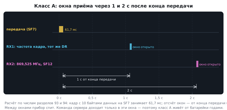
All devices must support class A. Receive windows in the bench's region: RX1 1 s after the end of transmission, on the frame's frequency; RX2 after 2 s on 869.525 MHz at DR0 (SF12). These are the region defaults: a network can set its own, often SF9 for RX2. With OTAA the device gets them in the join reply; with ABP they are written into the device by hand. A command for a class A device waits in the server queue until the device itself makes contact.
The window is opened by a timer started at "transmission finished", which is DIO0 from section 93, not by a delay loop (section 13). If the window is opened late, the server's replies never arrive, and the device looks "deaf".
The window accuracy in the LoRaWAN specification is ±20 µs, so the window timer is clocked from a crystal: LSE or HSE. The STM32 LSI is off by tens of percent (section 12), HSI by about 1 % (section 6), and 1 % of a second is 10 ms, more than the whole SF7 preamble: 8 symbols of 1.024 ms each are 8.2 ms. Stacks open the window a little early and keep it open longer to cover clock drift, and pay for it with receive current.
A reply is expensive. The gateway is half-duplex: while it transmits a reply to one device, it hears nobody. Confirmed frames need a reply to every frame. In a network of thousands of devices they are enabled only for rare important events, not for telemetry.
94.7 ADR: data rate from SNR
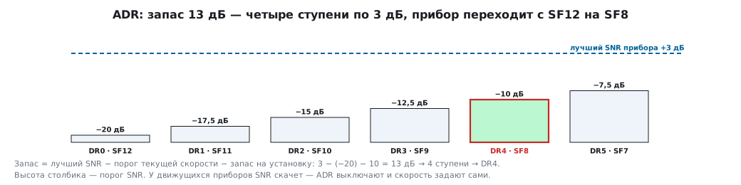
The network server remembers the SNR of the device's last frames and computes the margin: the best SNR minus the threshold for the current data rate (section 93.2) minus the installation margin, usually 10 dB. Every 3 dB of margin is one data rate step up. When there is nowhere faster to go, the server lowers the power.
| DR | 0 | 1 | 2 | 3 | 4 | 5 |
|---|---|---|---|---|---|---|
| SF at 125 kHz | 12 | 11 | 10 | 9 | 8 | 7 |
| SNR threshold, dB | −20 | −17.5 | −15 | −12.5 | −10 | −7.5 |
Example: a device at SF12 with a best SNR of +3 dB has a margin of 3 − (−20) − 10 = 13 dB. That is 4 steps, and the server moves the device to DR4, SF8. The packet becomes several times shorter, the battery lasts longer, and the air is freed for others. ADR is good for stationary devices. For moving ones the SNR jumps around, so ADR is turned off for them and the data rate is set by the device itself.
94.8 A device on STM32: what to store and what to send
- The stack. MAC commands, receive windows, joining and ADR are a ready-made LoRaWAN stack, usually from the radio module vendor. The code in this section is there so you understand what is inside and can test it.
- What to store. The frame counter (for ABP) and the session (for OTAA) are kept in non-volatile memory so they survive a reboot. Otherwise frames are dropped or, worse, the cipher keystream repeats.
- DevNonce. For OTAA, also store the join request number: the server remembers used numbers and rejects a repeat; in ChirpStack this is the error "DevNonce has already been used". Since LoRaWAN 1.0.4, DevNonce is a counter that must increase and survive a reboot. A device that restarts it after a reset will not be able to join after its very first reboot.
- The counter. The frame holds only the 16 low bits. A device that sends once every 10 minutes goes through them in 455 days. The server restores the high bits, and the device's stack keeps the full 32-bit counter.
- What to send. Data in binary, not as text and not as JSON. The string
t=21.50is 7 bytes, while the temperature in hundredths of a degree in anint16_tis 2 bytes. At SF12, where a packet lasts one and a half seconds (section 89), every byte counts.
94.9 Pitfalls
The server silently does not see the device. The address or a key was entered in the wrong byte order. The server log says that no session gave a valid signature.
After a reboot the ABP device went silent. The counter started from zero, and the server expects more than the previous one: "frame counter did not increase".
The counter was reset together with the server database, but the keys were kept. The keystream repeats, and the data can be recovered without the key.
Commands do not reach the device. The RX1 window opens later than 1 s: the delay loop drifted because of interrupts, or the window timer runs from the LSI.
After a reboot the OTAA device cannot join. DevNonce restarted from the beginning, and the server remembers the used numbers.
The network is choking. All devices send confirmed frames, and the gateway transmits more than it listens.
The battery runs flat in months instead of years. The device sends JSON at SF12.
The keys leaked from the firmware. They were in the image as a plain array.
94.10 Summary
- LoRaWAN is a star of stars. Gateways are transparent, all the logic is on the network server, and the application server decrypts the data.
- Two session keys: NwkSKey signs, AppSKey encrypts. The network operator does not read the data.
- A frame is 13 overhead bytes plus data. The address and the counter are written least significant byte first.
- The counter protects against replay and is part of the cipher, so it must not be repeated with the same keys. On the ChirpStack bench, a replay and a corrupted signature were dropped, and two honest frames were accepted and decrypted.
- The address is not unique, and the signature identifies the device.
- Class A listens in two windows after a transmission: 1 s and 2 s. Class C listens all the time and runs on mains power.
- ADR moves the device one step faster for every 3 dB of margin.
Next: section 94а "NFC tag ST25DV": how the phone and the firmware share one memory: addresses on the bus, the password, the mailbox and the interrupt on write.