 Embedded HandbookApps
93. LoRa: the radio, the SX1276 module, range
In section 89, LoRa is one row in a table and a formula for airtime. Here we look inside: why LoRa can be heard below the noise level, what each SF step costs, how to estimate range and how to connect the most common module to the F103 and the F407.
Verified: the demodulator in C works in a model with noise, and the threshold was recomputed independently in numpy. The SX1276 driver runs against a model of the chip, and the SPI port is built for both chips. The LoRaWAN network on top of this radio is section 94.
Terms used in the documentation
Term Meaning chirp, upchirp, downchirp a chirp is a signal whose frequency changes linearly; rising, falling chirp spread spectrum (CSS) spreading the spectrum with chirps spreading factor (SF) how many bits one symbol carries bandwidth (BW) the channel width coding rate (CR) code redundancy: 4/5…4/8 sync word the synchronization word explicit / implicit header a header sent in the packet / one both sides know in advance low data rate optimization (LDRO) the setting for very long symbols processing gain the gain the receiver gets from processing sensitivity, noise figure (NF) the weakest usable signal, the noise the receiver adds link budget, path loss the losses a link can afford, the losses along the path RSSI, SNR received signal power, signal-to-noise ratio PA_BOOST the output of the transmitter's high-power amplifier
93.1 The chirp: a symbol is a shift
A chirp is a signal whose frequency sweeps evenly across the whole band, from bottom to top, during one symbol. A chirp on its own carries nothing. A symbol is a shift of the start: the chirp does not begin at the lowest frequency but at one of 2^SF points, and when it reaches the top it continues from the bottom. With SF7 there are 128 such points, so a symbol carries 7 bits; with SF12 there are 4096 points and 12 bits.
The symbol duration is 2^SF / BW: in a 125 kHz band it is 1.024 ms for SF7 and 32.768 ms for SF12. Each SF step doubles the symbol and adds only one bit, so the data rate almost halves. With coding rate 4/5, SF7 gives 5469 bit/s.
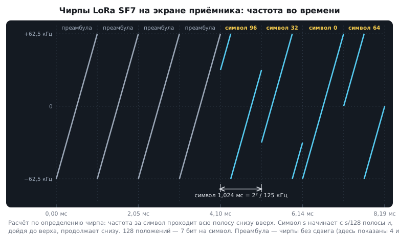
A symbol and its reception in the C model, with samples at a rate equal to the bandwidth:
/* Фаза опорного чирпа в долях π/N: (k² − N·k) mod 2N — в целых, без потери точности */
static uint32_t chirp_phase(uint32_t k, uint32_t n)
{
    return (k * k + 2u * n - (n * k) % (2u * n)) % (2u * n);
}

/* Символ s: опорный чирп, сдвинутый по кругу на s отсчётов; n = 2^sf отсчётов
 * на частоте, равной полосе */
void lora_symbol(float *re, float *im, unsigned sf, unsigned s)
{
    uint32_t n = 1u << sf;
    for (uint32_t k = 0; k < n; k++) {
        float ph = LORA_PI * (float)chirp_phase((k + s) % n, n) / (float)n;
        re[k] = cosf(ph);
        im[k] = sinf(ph);
    }
}

/* Демодуляция: умножить на сопряжённый опорный чирп — символ превращается
 * в чистый тон на частоте s, — и найти самый сильный отсчёт спектра.
 * re/im портятся: на их месте остаётся спектр. */
unsigned lora_demod(float *re, float *im, unsigned sf)
{
    uint32_t n = 1u << sf;
    for (uint32_t k = 0; k < n; k++) {
        float ph = -LORA_PI * (float)chirp_phase(k, n) / (float)n;
        float c = cosf(ph), s = sinf(ph);
        float r = re[k] * c - im[k] * s;
        im[k] = re[k] * s + im[k] * c;
        re[k] = r;
    }
    fft(re, im, n);
    unsigned best = 0;
    float peak = -1.0f;
    for (uint32_t k = 0; k < n; k++) {
        float p = re[k] * re[k] + im[k] * im[k];
        if (p > peak) {
            peak = p;
            best = k;
        }
    }
    return best;
}
fft is an ordinary in-place fast Fourier transform. The phase is computed in
integers. The value k² itself still fits exactly in a float at SF12
(4095² = 16769025 < 2^24), but the angle π·k·(k − N)/N reaches thousands of
radians: the float step at such an angle is ten-thousandths of a radian, and sinf
and cosf lose even more with a large argument. Reducing modulo 2N
in integers keeps the angle between 0 and 2π.
The key part here is the demodulator. Multiplying by the reference chirp "removes" the frequency slope from the symbol, and the shift s turns into a pure tone at frequency s. The Fourier transform shows that tone as a single peak, and the index of the peak is the symbol. The chip does the same thing in hardware. The same code is built for the F407 with an FPU and takes 160 bytes of stack, but in a real device this work is done by the radio module.
93.2 Why LoRa can be heard below the noise
The Fourier transform collects the energy of all 2^SF samples of a symbol into one spectrum bin, while the noise stays spread over all of them. The gain is 10·lg 2^SF: 21.1 dB at SF7 and 36.1 dB at SF12. That is why a LoRa receiver can decode a signal that is weaker than the noise in the band: the signal-to-noise ratio is negative.
The C model: for each SF, a thousand random symbols in noise; the SNR is lowered in steps of 0.5 dB until errors exceed 1 %. The same experiment was repeated independently in numpy with its own noise generator, and the thresholds matched to within one step, 0.5 dB:
| SF | Symbol | Model threshold | Threshold for calculations |
|---|---|---|---|
| 7 | 1.024 ms | −9.0 dB | −7.5 dB |
| 8 | 2.048 ms | −11.5 dB | −10.0 dB |
| 9 | 4.096 ms | −14.5 dB | −12.5 dB |
| 10 | 8.192 ms | −17.0 dB | −15.0 dB |
| 11 | 16.384 ms | −20.0 dB | −17.5 dB |
| 12 | 32.768 ms | −22.5 dB | −20.0 dB |
Each SF step gives 2.5–3 dB. A real receiver also has to find the start of the packet and track the drift of the crystal frequency, so its thresholds are 1.5–2.5 dB worse than the ideal model. For range calculations, take the thresholds from the chip documentation: the right-hand column.
Packets with different SF on the same channel hardly interfere with each other, and a gateway receives them at the same time. This is how a LoRaWAN network receives: devices near the gateway work at SF7, devices at the edge at SF12, and they all share one channel.
93.3 Packet parameters
| Parameter | Values | What it gives | What it costs |
|---|---|---|---|
| SF | 7–12 | 2.5–3 dB per step | twice the airtime |
| bandwidth | 125, 250, 500 kHz | wider is faster | each doubling costs 3 dB of sensitivity |
| coding rate | 4/5…4/8 | error correction | a longer packet |
| preamble | 8 symbols plus another 4.25 | the receiver catches the start of the packet | time |
| sync word | 0x34 for LoRaWAN, 0x12 for private networks | other networks are filtered out | — |
| header | explicit or implicit | explicit carries the length and coding rate | with implicit, both sides know them in advance |
| CRC | on | a corrupted packet is rejected | 2 bytes |
| low data rate optimization | SF11–12 at 125 kHz | long symbols tolerate frequency drift | must match on both sides |
Frequency, SF, bandwidth, sync word and low data rate optimization must match on the transmitter and the receiver. If anything differs, the packet is not received, and no error tells you so.
Bandwidth is the second lever after SF. A packet with 10 bytes of LoRaWAN data at SF7 takes 61.7 ms at 125 kHz and 15.4 ms at 500 kHz. But each doubling of the bandwidth costs 3 dB of sensitivity: a wider band contains more noise.
93.4 Link budget: how many kilometres
Thermal noise is −174 dBm per hertz of bandwidth. In a 125 kHz band that is −174 + 10·lg 125000 = −123.0 dBm. The receiver adds its own noise (the noise figure; take 6 dB), and the demodulator needs its SNR threshold on top:
| SF | 7 | 8 | 9 | 10 | 11 | 12 |
|---|---|---|---|---|---|---|
| sensitivity, dBm | −124.5 | −127.0 | −129.5 | −132.0 | −134.5 | −137.0 |
The link budget is the transmitter power plus the antenna gains minus the cable losses minus the sensitivity. At 14 dBm and with antennas without gain it is 138.5 dB at SF7 and 151.0 dB at SF12. That is how much the signal can lose on the way.
A power of 14 dBm, that is 25 mW, is the European limit for the main bands 868.0–868.6 MHz (at 1 % duty cycle) and 868.7–869.2 MHz (at 0.1 %). In the 869.4–869.65 MHz band 500 mW (27 dBm) is allowed at 10 % duty cycle: the second LoRaWAN receive window works there, and the 17 dBm at 869.525 MHz from the experiment in 93.5 stays within the limit. The limit applies to radiated power: an antenna with gain uses up part of the allowance, and the power at the chip output is reduced by the same amount. For the rules of a particular country, see its frequency regulations.
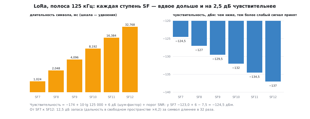
In free space, 151 dB at 868 MHz is almost 1000 km. Near the ground you get kilometres: the curvature of the Earth, terrain, buildings, forest and walls get in the way. On top of that you need a margin of 10 dB or more for fading. How to measure the real losses on site is section 92.
Two rules are useful for any estimate:
- in free space every 6 dB doubles the range, so the 12.5 dB between SF7 and SF12 is ×4.2 in range; near the ground the losses grow faster with distance, and the gain is smaller;
- every decibel counts: a "spring" coil antenna instead of an 8.6 cm whip (section 89), an extra metre of thin cable, a metal enclosure.
93.5 🔧 The SX1276 module over SPI
RFM95 and similar modules are built on the SX1276 chip. The connection to the F103 and the F407 is the same:
| Module pin | STM32 | Purpose |
|---|---|---|
| NSS | PA4 | chip select, active low |
| SCK | PA5 | SPI1 clock |
| MISO | PA6 | data from the module |
| MOSI | PA7 | data to the module |
| RESET | PB0 | reset, active low |
| DIO0 | PB1 | event: transmission finished or packet received |
| 3.3 V, GND | — | 3.3 V supply only |
⚠️ Do not transmit without an antenna. The power reflected from an unconnected output damages the transmitter amplifier. And check the module's band: some modules are made for 868–915 MHz, others for 433 MHz; firmware cannot fix that.
SPI is mode 0, no faster than 10 MHz. On the F103 the APB2 bus runs at 72 MHz, and a prescaler of 8 gives 9 MHz. On the F407 APB2 is at 84 MHz: a prescaler of 8 would give 10.5 MHz, which is above the limit, so the prescaler is 16, giving 5.25 MHz:
void sx_port_init(void)
{
#if defined(STM32F10X_MD)
    RCC->APB2ENR |= RCC_APB2ENR_IOPAEN | RCC_APB2ENR_IOPBEN | RCC_APB2ENR_SPI1EN;
    /* PA7, PA5 — альтернативная функция 50 МГц (1011), PA6 — вход (0100), PA4 — выход (0011) */
    GPIOA->CRL = (GPIOA->CRL & 0x0000FFFFu) | 0xB4B30000u;
    /* PB1 — вход (0100), PB0 — выход с открытым стоком (0111): «1» отпускает RESET */
    GPIOB->CRL = (GPIOB->CRL & 0xFFFFFF00u) | 0x00000047u;
    /* APB2 72 МГц / 8 = 9 МГц: у SX1276 предел 10 МГц; режим 0 */
    SPI1->CR1 = SPI_CR1_MSTR | SPI_CR1_BR_1 | SPI_CR1_SSM | SPI_CR1_SSI | SPI_CR1_SPE;
    SysTick_Config(72000000u / 1000u);
#elif defined(STM32F407xx)
    RCC->AHB1ENR |= RCC_AHB1ENR_GPIOAEN | RCC_AHB1ENR_GPIOBEN;
    RCC->APB2ENR |= RCC_APB2ENR_SPI1EN;
    /* PA7–PA5 — альтернативная функция 5 (SPI1), PA4 — выход */
    GPIOA->MODER = (GPIOA->MODER & ~0x0000FF00u) | 0x0000A900u;
    GPIOA->AFR[0] = (GPIOA->AFR[0] & ~0xFFF00000u) | 0x55500000u;
    /* PA5–PA7 — быстрые фронты (10): после сброса скорость низкая, не выше 4 МГц */
    GPIOA->OSPEEDR = (GPIOA->OSPEEDR & ~0x0000FC00u) | 0x0000A800u;
    /* PB1 — вход, PB0 — выход с открытым стоком: «1» отпускает RESET */
    GPIOB->OTYPER |= 1u;
    GPIOB->MODER = (GPIOB->MODER & ~0x0000000Fu) | 0x00000001u;
    /* APB2 84 МГц / 16 = 5,25 МГц: делитель 8 дал бы 10,5 МГц — выше предела */
    SPI1->CR1 = SPI_CR1_MSTR | SPI_CR1_BR_1 | SPI_CR1_BR_0 | SPI_CR1_SSM | SPI_CR1_SSI | SPI_CR1_SPE;
    SysTick_Config(168000000u / 1000u);
#endif
    sx_select(0);
    sx_reset_pin(1);
}

void sx_select(int on)
{
    if (on) {
        GPIOA->BSRR = 1u << (4 + 16);           /* PA4 = 0: микросхема выбрана */
    } else {
        while (SPI1->SR & SPI_SR_BSY) { }       /* дождаться хвоста посылки (раздел 18.5) */
        GPIOA->BSRR = 1u << 4;
    }
}

uint8_t sx_spi(uint8_t b)
{
    while (!(SPI1->SR & SPI_SR_TXE)) { }
    SPI1->DR = b;
    while (!(SPI1->SR & SPI_SR_RXNE)) { }
    return (uint8_t)SPI1->DR;
}
Reset is open-drain. While the chip goes through its own power-on reset,
the documentation says to leave its NRESET pin floating,
and a push-pull "1" on it interferes with that. So PB0 is an open-drain
output: "0" pulls the pin to ground, "1" releases it. A manual reset is
a low level for at least 100 µs, then release and wait 5 ms; sx_init holds
it low for 1 ms and waits 10.
Edge speed on the F407. After reset, PA5–PA7 have low speed: no
more than 4 MHz with a 50 pF load, edges up to 100 ns, and the clock here is 5.25 MHz.
On the F103 the speed is set explicitly in the code (50 MHz); on the F407 it is raised
in OSPEEDR.
The rest of the port is the reset pin, a SysTick delay and reading DIO0. The driver above it is portable: it knows only four port functions.
Registers the driver needs:
| Register | Address | What it holds |
|---|---|---|
| RegFifo | 0x00 | a window into the 256-byte packet buffer |
| RegOpMode | 0x01 | bit 7 is LoRa; bits 2–0 are sleep, standby, transmit, receive |
| RegFrf | 0x06–0x08 | frequency, step 61.035 Hz |
| RegPaConfig | 0x09 | PA_BOOST output and power |
| FIFO pointers | 0x0D–0x10 | current, TX base, RX base, last packet |
| RegIrqFlags | 0x12 | TxDone, RxDone, CRC error; cleared by writing ones |
| RegRxNbBytes | 0x13 | length of the received packet |
| RegPktSnr, RegPktRssi | 0x19, 0x1A | SNR and power of the packet |
| RegModemConfig1, 2, 3 | 0x1D, 0x1E, 0x26 | bandwidth and coding rate; SF and CRC; optimization and AGC |
| RegSyncWord | 0x39 | sync word |
| RegDioMapping1 | 0x40 | which event goes to DIO0 |
| RegVersion | 0x42 | 0x12 for the whole SX1276…SX1279 family: a check that a chip of this family is on the bus; it does not tell the module's band (868 or 433 MHz) |
An address with the top bit clear is a read; with the top bit set, a write. The FIFO is accessed through the single address 0x00: the pointer inside increments by itself with each byte.
struct sx_cfg {
    uint32_t freq_hz;                   /* например, 868 100 000 */
    uint8_t sf;                         /* 7…12 */
    uint8_t bw;                         /* код полосы: 7 — 125 кГц, 8 — 250, 9 — 500 */
    uint8_t cr;                         /* 1…4 — избыточность 4/5…4/8 */
    uint8_t sync;                       /* 0x34 — LoRaWAN, 0x12 — частные сети */
    int8_t power_dbm;                   /* 2…17 на выходе PA_BOOST */
};

/* Вернёт 0 или −1, если на шине не SX1276: регистр версии обязан быть 0x12 */
int sx_init(const struct sx_cfg *c)
{
    sx_reset_pin(0);
    sx_delay_ms(1);
    sx_reset_pin(1);
    sx_delay_ms(10);
    if (sx_read(REG_VERSION) != 0x12)
        return -1;
    sx_write(REG_OP_MODE, MODE_SLEEP);                /* режим LoRa меняют только во сне */
    sx_write(REG_OP_MODE, MODE_LORA | MODE_SLEEP);
    uint32_t frf = (uint32_t)(((uint64_t)c->freq_hz << 19) / 32000000u);   /* шаг 61,035 Гц */
    sx_write(REG_FRF_MSB, (uint8_t)(frf >> 16));
    sx_write(REG_FRF_MSB + 1, (uint8_t)(frf >> 8));
    sx_write(REG_FRF_MSB + 2, (uint8_t)frf);
    sx_write(REG_PA_CONFIG, (uint8_t)(0x80 | (c->power_dbm - 2)));        /* PA_BOOST: 2 + N дБм */
    sx_write(REG_FIFO_TX_BASE, 0);
    sx_write(REG_FIFO_RX_BASE, 0);
    sx_write(REG_MODEM_CONFIG1, (uint8_t)((c->bw << 4) | (c->cr << 1)));  /* заголовок явный */
    sx_write(REG_MODEM_CONFIG2, (uint8_t)((c->sf << 4) | 0x04));          /* CRC включён */
    int ldro = (c->bw == 7 && c->sf >= 11) || (c->bw == 8 && c->sf == 12);   /* символ > 16 мс */
    sx_write(REG_MODEM_CONFIG3, (uint8_t)((ldro ? 0x08 : 0) | 0x04));      /* и AGC */
    sx_write(REG_PREAMBLE_MSB, 0);
    sx_write(REG_PREAMBLE_LSB, 8);
    sx_write(REG_SYNC_WORD, c->sync);
    sx_write(REG_OP_MODE, MODE_LORA | MODE_STDBY);
    return 0;
}

/* Отправить пакет и дождаться конца передачи; 0 или −1 по таймауту.
 * После передачи микросхема сама возвращается в ожидание. */
int sx_send(const uint8_t *buf, uint8_t n, unsigned timeout_ms)
{
    sx_write(REG_OP_MODE, MODE_LORA | MODE_STDBY);
    sx_write(REG_FIFO_ADDR_PTR, 0);
    sx_fifo_write(buf, n);
    sx_write(REG_PAYLOAD_LENGTH, n);
    sx_write(REG_DIO_MAPPING1, 0x40);                 /* DIO0 — «передача окончена» */
    sx_write(REG_IRQ_FLAGS, 0xFF);                    /* флаги сбрасывают записью единиц */
    sx_write(REG_OP_MODE, MODE_LORA | MODE_TX);
    while (!(sx_read(REG_IRQ_FLAGS) & IRQ_TX_DONE)) {
        if (timeout_ms-- == 0)
            return -1;
        sx_delay_ms(1);
    }
    sx_write(REG_IRQ_FLAGS, IRQ_TX_DONE);
    return 0;
}

/* Забрать пакет: длина, 0 — ничего не пришло, −1 — ошибка CRC.
 * Мощность — в дБм (вход выше 779 МГц), SNR — в четвертях децибела. */
int sx_receive(uint8_t *buf, uint8_t cap, int *rssi_dbm, int *snr_q)
{
    uint8_t f = sx_read(REG_IRQ_FLAGS);
    if (!(f & IRQ_RX_DONE))
        return 0;
    sx_write(REG_IRQ_FLAGS, f);
    if (f & IRQ_CRC_ERROR)
        return -1;
    uint8_t n = sx_read(REG_RX_NB_BYTES);
    if (n > cap)
        n = cap;
    sx_write(REG_FIFO_ADDR_PTR, sx_read(REG_FIFO_RX_CURRENT));
    sx_fifo_read(buf, n);
    int snr = (int8_t)sx_read(REG_PKT_SNR);
    int rssi = -157 + sx_read(REG_PKT_RSSI);
    if (snr < 0)
        rssi += snr / 4;                              /* ниже шума мощность уточняют по SNR */
    *rssi_dbm = rssi;
    *snr_q = snr;
    return n;
}
sx_listen turns on continuous receive and switches DIO0 to "packet
received". Instead of polling the flags, DIO0 is wired to an EXTI interrupt (section 7).
Under an RTOS, the interrupt handler wakes the radio task and reads nothing
over SPI itself.
The frequency needs 64 bits. 868100000 · 2^19 does not fit in 32 bits.
A frequency register computed in uint32_t silently overflows, and the module
goes to the wrong frequency.
Testing on a model. There is no chip on the desk, so the driver works with a C model of the SX1276. The model holds the registers, a FIFO with an incrementing pointer and flags that are cleared by writing ones, and it enforces the rule "the LoRa bit can change only in sleep":
| What was tested | Result |
|---|---|
| writing 0x81 to RegOpMode outside sleep | mode 0x01: the LoRa bit is ignored, the module stays in FSK |
sx_init: 868.1 MHz, SF7, 125 kHz, 4/5, 14 dBm |
Frf D9 06 66, PaConfig 8C, ModemConfig 72 74 04, SyncWord 34 |
| 869.525 MHz, SF12, 17 dBm | Frf D9 61 99, PaConfig 8F, ModemConfig2 C4, ModemConfig3 0C: optimization is on |
| a different chip on the bus | sx_init returned −1 |
sx_send of 11 bytes |
the bytes left the FIFO, the flag was cleared, the chip returned to standby |
| a packet below the noise | SNR −7.5 dB, power −124 dBm |
| CRC error | −1, flags cleared, the next packet received |
The configuration bytes were recomputed independently in Python.
93.6 RSSI and SNR: how to read them
The chip reports two numbers for each packet. SNR is in signed quarters of a decibel. Power is −157 plus the register value for inputs above 779 MHz; for 433 MHz modules the offset is different, −164. When the SNR is negative, the power is corrected by a quarter of the SNR: the signal is below the noise, and the power register mostly sees noise.
To judge a link, SNR matters more than power. A power of −110 dBm in an open field and in a workshop full of frequency inverters are two different links, and SNR shows that difference. The margin to the SF threshold is the main indicator: a packet at SF7 with an SNR of −6 dB got through, but only one and a half decibels were left to the threshold. Both numbers are recorded during a radio survey (section 92). The LoRaWAN network also uses them to choose an SF for the device (section 94).
93.7 Pitfalls
The module is silent, RegVersion reads as 0x00 or 0xFF. MISO and MOSI are swapped, the SPI mode is wrong, or NSS does not go low.
The module does not transmit, although all registers are written. The LoRa bit was written outside sleep: the chip ignored it and stayed in FSK.
The transmitter is on the wrong frequency. The frequency register was computed in 32 bits or
through float with rounding.
SPI is unreliable on the F407. A prescaler of 8 from 84 MHz gives 10.5 MHz, above the chip's
limit. Or PA5–PA7 still have the low edge speed left after reset:
raise it in OSPEEDR.
Packets do not arrive, and there are no errors. The transmitter and the receiver have different SF, bandwidth, sync word or low data rate optimization.
Reception went silent after the first packet. The flags were not cleared by writing ones to RegIrqFlags.
The last bit of a command is cut off. NSS was released before BSY cleared.
The transmitter output is damaged. It transmitted without an antenna.
The battery of a device at the edge of coverage drains before your eyes. It runs at SF12: a packet lasts 1.48 s against 61.7 ms at SF7 (section 89).
93.8 Summary
- A LoRa symbol is a shift of the chirp. SF bits per symbol, duration 2^SF / BW: 1.024 ms at SF7 and 32.768 ms at SF12 with a 125 kHz bandwidth.
- The receiver removes the chirp and finds the spectrum peak. The gain is 10·lg 2^SF, so LoRa decodes signals below the noise: in the model the threshold is from −9 dB at SF7 to −22.5 dB at SF12; in real chips it is from −7.5 to −20 dB.
- Each SF step is 2.5–3 dB and twice the airtime; each doubling of the bandwidth is twice as fast and 3 dB worse.
- The link budget at 14 dBm is 138.5 dB at SF7 and 151 dB at SF12. How many kilometres that is depends on the terrain (section 92).
- The SX1276 connects over SPI1 the same way to the F103 and the F407; compute the frequency in 64 bits, set the LoRa bit in sleep, clear the flags with ones, never transmit without an antenna.
Next: section 93а "nRF24L01: a 2.4 GHz radio over SPI — addresses, channels, Enhanced ShockBurst, acknowledgements and retransmits".