 Embedded HandbookApps
165. Noise: addition, resistors, the amplifier, 1/f and the ADC budget
Noise is the only error that cannot be calibrated out: it is random. All you can do is keep it out of the path — choose the resistances, the amplifier and the bandwidth. This section is about how to calculate how much noise reaches the ADC input, how to decide whether it is worth fighting, and when noise actually helps.
Terms used in the documentation
Term Meaning thermal (Johnson) noise noise of any resistor due to temperature voltage noise density (en) amplifier noise voltage per root hertz current noise density (in) amplifier noise current per root hertz source impedance internal resistance of the signal source 1/f (flicker) noise noise that rises towards low frequencies corner frequency where 1/f noise equals white noise noise bandwidth equivalent bandwidth for noise calculation root sum of squares (RSS) square root of the sum of squares input-referred noise noise recalculated to the input peak-to-peak noise full span of the noise quantization noise error from rounding to a code oversampling / averaging taking extra samples / averaging them dither noise added on purpose signal-to-noise ratio (SNR) ratio of signal to noise
165.1 Noise adds as a root
Independent noise sources do not add directly — their
squares add: U = √(U₁² + U₂² + …). Two equal sources of 2 µV each give
2.83 µV, not 4. A 10 µV source and a 1 µV source together give 10.05 µV:
the smaller source is almost invisible.
Hence the first rule of fighting noise: find the strongest source and work only on it. Reducing a weak one tenfold gains less than a percent.
165.2 Thermal noise of a resistor
Every resistor makes noise: U = √(4 · k · T · R · Δf). In the 20 Hz…20 kHz band
at 25 °C the ngspice model gives:
| Resistor | Noise |
|---|---|
| 100 kΩ | 5.74 µV |
| 10 MΩ | 57.4 µV |
A resistance a hundred times larger gives ten times more noise: it grows as the square root of the resistance and of the bandwidth.
165.3 Amplifier and stage noise
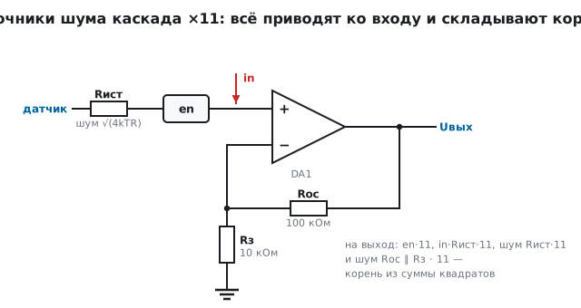
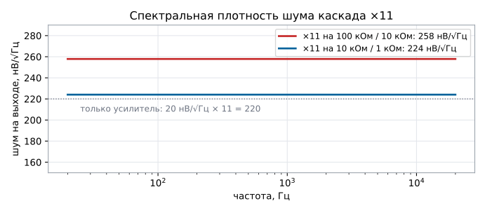
Amplifier noise is specified as a spectral density referred to the input — for example, 20 nV/√Hz. In a ×11 stage it reaches the output together with the noise of the feedback resistors. Model, 20 Hz…20 kHz band:
| ×11 stage | Output noise |
|---|---|
| amplifier only, 20 nV/√Hz (calculated) | 31.1 µV |
| amplifier and 100 kΩ / 10 kΩ resistors | 36.5 µV |
| amplifier and 10 kΩ / 1 kΩ resistors | 31.7 µV |
| 100 kΩ / 10 kΩ resistors only | 19.0 µV |
With 100 kΩ / 10 kΩ resistors their noise is already a noticeable share; by reducing the resistances tenfold at the same gain, we get almost the noise of the amplifier alone. Below a certain level the noise is set only by the part, and from there only a part with lower density helps.
165.4 Current noise and source resistance
An amplifier has a second noise — current noise in. By itself it is invisible:
it becomes a voltage only across a resistance it flows through.
A follower with 20 nV/√Hz voltage noise on a sensor with an internal
resistance of 1 MΩ, 20 Hz…20 kHz band:
| Follower on a 1 MΩ source | Output noise |
|---|---|
| thermal noise of the source only | 18.1 µV |
| FET input, 1 fA/√Hz | 18.4 µV |
| bipolar input, 0.5 pA/√Hz | 73.0 µV |
For the bipolar input the current noise on a megohm gives 0.5 pA/√Hz × 1 MΩ = 500 nV/√Hz — 25 times its own voltage noise, and four times the noise of the FET input. For a FET input the current noise is negligible, and only the noise of the sensor itself remains — it cannot get any lower.
The boundary between "voltage noise matters" and "current noise matters" is the ratio
en / in: here 20 nV / 0.5 pA = 40 kΩ. For a source well below this
resistance, choose the amplifier by voltage noise; above it, by current
noise — and for high-impedance sensors (photodiode, piezo sensor, electrochemical
sensor) a FET input is used.
165.5 1/f noise and the corner frequency
At low frequencies amplifier noise grows as 1/√f — this is 1/f noise. The frequency
at which it equals the white noise is the corner frequency fc. The total noise in
the band fmin…fmax:
U = en · √(fc · ln(fmax / fmin) + fmax − fmin)
For a 20 nV/√Hz amplifier with a 100 Hz corner, in the 0.1…10 Hz band — the one where slow sensors live: 434 nV. White noise in this band is only 63 nV — 1/f noise is seven times larger. That is why precise slow measurements use amplifiers with a low corner frequency or with auto-zero, and a filter cannot remove it: it is in the same band as the signal.
165.6 Bandwidth decides everything
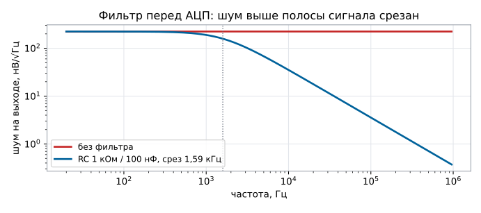
Noise grows as the square root of the bandwidth, and without a filter the bandwidth is limited only by the amplifier itself. A ×11 stage on 10 kΩ / 1 kΩ:
| Bandwidth | Output noise |
|---|---|
| 20 Hz…1 MHz, no filter, ideal amplifier | 219 µV |
| the same stage + RC 1 kΩ / 100 nF (corner 1.59 kHz) | 11.2 µV |
| no filter, amplifier with 1 MHz bandwidth: the ×11 stage cuts off at 91 kHz | 82 µV |
| the same + RC 1 kΩ / 100 nF | 11.1 µV |
In the model with an ideal amplifier the filter removes noise twentyfold. A real amplifier with 1 MHz bandwidth (sections 162–164) itself cuts everything above 91 kHz, and the filter gains about sevenfold. In both cases a filter in front of the ADC that cuts everything above the signal band is cheaper than any low-noise part.
165.7 Noise budget for the ADC
One code of a 12-bit ADC with a 3.3 V scale is 806 µV. Peak-to-peak noise is roughly 6.6 times its RMS value: 11.2 µV after the filter is about 74 µV peak-to-peak, ten times less than a code. Such a path shows stable codes, and there is no need to deal with noise.
The calculation goes like this: 1. refer all sources to one point (usually the ADC input); 2. add them as a root sum of squares and multiply by 6.6 — this gives the peak-to-peak value; 3. compare with the ADC code: if the peak-to-peak noise is less than a code, the noise is not visible; if it is more — first narrow the bandwidth, then reduce the resistances, and only then change the amplifier.
165.8 Quantization and averaging
The ADC itself also adds an error: rounding to a code is uniformly distributed
within a code, and its RMS value is code / √12, 232.6 µV.
The signal-to-noise ratio of an ideal 12-bit ADC is 74.0 dB. The quiet
path from 165.7 is invisible against this background: √(11.2² + 232.6²) = 232.8 µV.
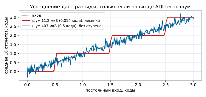
Averaging N samples reduces the random error by √N: 16 samples — fourfold, that is two more bits. But only if there is noise. An experiment: an ideal 12-bit ADC, a constant input from 0 to 3 codes, the average of 16 samples:
| Noise at the ADC input | Error of the average |
|---|---|
| 11.2 µV (0.014 code) — the path from 165.7 | staircase, up to 0.49 code |
| 403 µV (0.5 code) | 0.14 code, no steps |
The quiet path gives 16 identical samples, and the average repeats the staircase.
With half a code of noise the samples spread over neighbouring codes, and their average
follows the input smoothly; the random error is √((0.5² + 1/12) / 16)
= 0.144 code: the squares of noise and quantization add up and are divided by 16,
so the RMS value drops fourfold.
A real ADC also has its own noise, and it mixes itself in: the samples even of a quiet path usually spread over neighbouring codes. Averaging gains √N only against white noise; it barely touches 1/f noise from 165.5 and drift.
Hence the dithering trick: noise or a sawtooth with a span of one or two codes is added on purpose to a path that is too quiet, so that averaging yields extra bits. The reverse is also true: if averaging is needed, the filter in front of the ADC must not cut the noise down to fractions of a code.
165.9 Pitfalls
A low-noise amplifier was fitted, and the noise did not drop. The noise was set by the resistors or the bandwidth, not by the part.
Megohm feedback "is noisy". Thermal noise grows as the square root of resistance: 10 MΩ is ten times noisier than 100 kΩ.
A high-impedance sensor is noisier than calculated. Amplifier current noise across the source resistance; a bipolar input on megohms — use a FET input.
A filter does not help a slow sensor. In a band of fractions of a hertz 1/f noise dominates; it cannot be filtered out — you need a part with a low corner.
ADC codes "jump" with a steady signal. The peak-to-peak noise is larger than a code; most often the filter in front of the ADC is missing.
Averaging did not add bits. The noise at the ADC input is much less than a code — all samples are identical; add noise or a sawtooth.
Noise sources were added directly and overestimated. Independent sources add as the root of the sum of squares.
165.10 Summary
- Independent noise adds as a root: 2 and 2 µV give 2.83 µV, 10 and 1 µV give 10.05 µV; only the strongest source is worth fighting.
- A 100 kΩ resistor in the 20 Hz…20 kHz band makes 5.74 µV of noise, 10 MΩ 57.4 µV.
- A ×11 stage with a 20 nV/√Hz amplifier: 36.5 µV on 100 kΩ / 10 kΩ and 31.7 µV on 10 kΩ / 1 kΩ.
- On a 1 MΩ source a bipolar input gives 73.0 µV, a FET input 18.4 µV; the selection boundary is en / in = 40 kΩ.
- 1/f noise with a 100 Hz corner in the 0.1…10 Hz band is 434 nV versus 63 nV of white noise.
- Without a filter, in the band up to 1 MHz — 219 µV with an ideal amplifier and 82 µV with a 1 MHz amplifier; a 1.59 kHz RC filter leaves 11.2 µV, with an ADC code of 806 µV.
- Quantization is 232.6 µV; averaging 16 samples works only with noise: without it a staircase up to 0.49 code, with half a code of noise 0.14 code.
Next: section 166 "Resistors in detail: TCR, pulse load, shunt, battery divider".