 Embedded HandbookApps
36з. Galvanic isolation in measurements: oscilloscope ground, isolated channels, differential probe
Section 36а.5 says it briefly: the probe ground clip is connected to the oscilloscope chassis, and the chassis to the protective earth of the outlet, so you never clip it to a point under voltage. Section 208.7 builds the proper bench for a mains-powered device. This section answers the questions that come right after that: why you cannot simply cut the earth off the oscilloscope plug, whether a battery-powered oscilloscope or one running from a power bank helps, how to look at several channels referenced to different points, why the difference of two ordinary channels "A − B" lies, and what a differential probe is actually good for.
Two terms you will need from here on. Galvanic isolation means there is no conductive path between two circuits: neither DC nor mains current flows through it, but the capacitance between the circuits remains. Common-mode voltage is the shared part of two inputs: if both measurement leads sit at 325 V relative to earth and differ from each other by 1 V, then 1 V is the difference (the useful signal) and 325 V is the common mode. The instrument must show the difference and ignore the common mode; how well it manages that is given by the common-mode rejection ratio (CMRR) in decibels.
Sources: the probe, its compensation and ground lead — 36а.2; the oscilloscope ground
and the Y capacitors of a power supply — 36а.5; oscilloscope inputs and channels —
36г, channel math — 36е; current through the body and the isolation
transformer — 208.1; the bench for a mains-powered device — 208.7; triac,
zero-cross detector and phase control — 208б.3–208б.6; isolation barrier
capacitance — 54.5; the difference amplifier and resistor spread — 56.5 and 176.2.
The author's oscilloscope is a RIGOL DHO900, and everything said about it comes from its
documents (numbers are PDF pages): the user guide
DHO900_UserGuide_EN.pdf — p. 17 (general safety rules, the probe
ground lead), p. 19 (measurement category), p. 28 and 41 (12 V power
over USB Type-C, the ground terminal on the rear panel), p. 277
(standard accessories); the datasheet dho900-datasheet.pdf — p. 6
(high-voltage probes), p. 10 (channel input: maximum voltage,
gain accuracy, resolution, "Channel-to-Channel Isolation"), p. 24
(power). Everything else in the section applies to any oscilloscope.
The numbers in this section are ngspice models and calculations in the stm-lab:1 container
(_verify/iso36z/run36z.sh). Measurement categories follow the standards
IEC 61010 and IEC 60664-1, which are not in the project: their figures were not checked
against the text of the standard (see the caption at the end).
What the documentation calls it
Original Meaning protective earth (PE), safety ground the third conductor of the outlet floating measurement the reference point is not at earth isolated channels, channel-to-channel isolation each channel has its own reference common-mode voltage the voltage shared by both inputs common-mode rejection ratio (CMRR) how strongly the common mode is suppressed pseudo-differential, math A − B a "differential" made by subtracting two channels common-mode transient immunity (CMTI), dV/dt tolerance to a fast common-mode jump measurement category (CAT II, CAT III, CAT IV) the class of circuit a meter may be connected to working voltage to earth the voltage relative to earth that a rating refers to Channel-to-Channel Isolation (in the datasheet) crosstalk suppression between channels, not galvanic isolation transient overvoltage, impulse withstand the impulse overvoltage the instrument must survive
36з.1 The oscilloscope ground is PE, and you do not cut it
A bench oscilloscope with a mains cord is a class I instrument: the metal chassis, the outer shells of all BNC connectors and the ground clips of all probes are connected to each other and to the third conductor of the plug, the protective earth PE (208.6). This ground is not there for measurement but for safety: if mains breaks down to the chassis inside the instrument, the current goes into PE and trips the breaker instead of going into your hand.
That also explains the price of a "cut ground". If you remove PE — with an adapter without an earth contact or a piece of tape on the pin — the chassis is no longer tied to earth, and the probe clip really can be attached to any point. But together with the clip, the whole chassis rises to the potential of that point: metal, knobs, the shells of all BNCs, the clips of the other channels, the shield of the USB and network connectors. If the point is the "minus" of a transformerless supply or the primary side of a switching supply, the chassis carries the same mains as the circuit: 230 V rms, 325 V peak. Whoever touches the chassis and something earthed — a radiator, a neighbouring instrument, the USB shield of a computer — gets a current limited only by the body: 230 mA through 1 kΩ of wet hands (208.1), more than seven times the fibrillation threshold. And no breaker trips: there is no longer any current "to earth through PE", and only an RCD (208.1) could save you.
Worse still, an oscilloscope without PE is not at "zero" even when nothing is connected: its own power supply holds the chassis through Y capacitors at about half the mains — the same picture as with the cheap supply in 36а.5 (115 V on a 230 V mains). The chassis tingles, and the very first touch of the probe to a board discharges that potential into its input.
How it is on the DHO900. It has no mains cord: power is 12 V, 4 A DC through a USB Type-C connector from an external adapter supplied in the box (user guide, p. 28 and 41). Next to the power connection the guide requires the instrument to be correctly grounded, and the rear panel has a separate ground terminal — connect the chassis to ground with a lead; a lead with a banana plug is a standard accessory (p. 41 and 277). The general rules (p. 17) say it plainly: the probe ground lead must be connected to earth ground and must not be connected to high voltage, otherwise a dangerous voltage appears on the connectors, controls and other surfaces of the oscilloscope. Whether the adapter output is connected to the PE of its plug, the documents do not say. So for the DHO900, PE is not about "not cutting" but about connecting: the rear-panel terminal goes to the protective earth of the bench or the outlet, and you check with an ohmmeter that the BNC shell and the outlet PE really are connected.
⚠️ Never cut PE on an oscilloscope. Not with an adapter, not "temporarily", not "I will be careful". You can measure under mains, but you isolate not the oscilloscope but the device or the channel — the methods are in 36з.2.
36з.2 Three correct ways
The task is the same: the measurement reference sits at mains potential, while the chassis of the instrument that you touch with your hands must stay at earth. There are three ways, and each has its price.
| Method | What is isolated | Pros | Cons |
|---|---|---|---|
| isolation transformer in front of the device under test | the whole device under test | an ordinary oscilloscope and ordinary probes, no loss of bandwidth or sensitivity | one common clip for all channels; an RCD behind the transformer does not work; transformer power not less than the load |
| oscilloscope with isolated channels (or battery-powered) | each input (or the whole instrument) | each channel has its own reference; full sensitivity | input capacitance to earth draws current on edges (36з.3, 36з.6); needs a rating for floating measurements (36з.7); price |
| differential probe | the probe input: two high-impedance arms | the oscilloscope stays on PE, the probe goes between any two points | common-mode rejection falls with frequency (36з.6); its own bandwidth, noise and voltage limit; one probe per channel |
An isolation transformer is what 208.1 and 208.7 describe: its secondary is not tied to earth, and touching one point means microamperes (7.2 µA through 100 pF of winding capacitance). But as soon as the oscilloscope clip lands on the device under test, that point has become earth, and all the others are relative to it. So all clips go only to that one point. And the transformer must carry the load: a heater of 2000 W draws 8.7 A, which means a transformer of at least 2000 VA, not a bench "isolator" of a hundred watts.
Isolated channels solve the task "in place": the channel input floats by itself, and each channel has its own reference. This is the best option when there are several channels with different references (36з.4) — but the isolation barrier is not ideal; it has capacitance (36з.3).
A differential probe isolates nothing galvanically: its arms are megohm dividers, and a tiny current flows through them. But the oscilloscope stays on its own earth, and the probe measures the difference between two points, neither of which has to be earth (208.7). This is the safest and most universal method, provided the probe is rated for the voltage and the category (36з.7).
36з.3 A battery-powered oscilloscope and one running from a power bank
A common question: a portable oscilloscope runs from its own battery or from a power bank over USB-PD, there is no mains in it — so can you attach the clip anywhere? Galvanically it really does float: there is no conductive path to earth. But three things remain.
Its channels are common. The clips of all channels are connected inside — this is one "ground" of the instrument. The whole instrument floats, but relative to one point. A second clip on another point of the circuit is a short circuit between those points through the instrument. The task "several channels from different references" (36з.4) is not solved by a battery.
The chassis is at the potential of the circuit. Clip on the "minus" of a mains circuit — and the whole instrument is at that potential: chassis, buttons, shielded connectors, the USB cable. This is not capacitive coupling but a wire, and the current through the body is limited only by the body: the same hand on the chassis and the other on something earthed — 230 mA (208.1). Holding such an instrument in your hands during a measurement is not allowed, and neither is connecting a laptop to it over USB (USB would tie the mains to the computer and to your hand on the keyboard).
The capacitance to earth has not gone anywhere. The instrument case, the battery,
the bench and the person nearby form a capacitance to earth — tens and hundreds
of picofarads. At 50 Hz only 7.2 µA flows through 100 pF. But the point
the clip sits on is not always the slow mains; it can be an edge: a triac
turned on at the crest of the sine — 325 V in a few microseconds, a switching
transistor — in tens of nanoseconds. Then i = C·dV/dt flows through the capacitance,
and it flows through the clip lead. The lead is an
inductance (150 nH for 15 cm, 36а.2), and the instrument shows the drop across it
as signal.
The DHO900 from a power bank. Readers discussed powering the DHO900 from a 65 W power bank over USB-C. What the documents say: the instrument needs 12 V and 4 A, up to 48 W with everything plugged into its connectors (datasheet, p. 24), and it is to be powered by the adapter from the box (user guide, p. 28). About USB Power Delivery, power banks and what the "key" in the adapter cable is, the documents say nothing at all: 65 W is more power than 48 W, but whether a particular power bank delivers 12 V at 4 A is not verified. The main point, though, is not power: an instrument on a power bank is not earthed, while the guide requires earthing and the probe ground at earth (p. 17 and 28). And its four channels are still connected through the chassis (36з.4).
Model (float36z.cir): the clip sits on a point that jumps by 325 V;
the tip is on the same point, so the correct answer is 0 V. The capacitance to earth
varies from an isolated channel to a power bank that is at that moment
charging from the mains through its charger:
.subckt flt src ch c=100p
Rs src ref 1
Lg ref m 150n
Rg m ch 0.05
Cs ch 0 {c}
.ends
| Input capacitance to earth | Current during a 1 µs edge | Peak error, 1 µs edge | Peak error, 50 ns edge |
|---|---|---|---|
| 10 pF — isolated channel | 3.2 mA | 0.40 V | 14.5 V |
| 30 pF — isolated channel | 9.8 mA | 0.68 V | 17.9 V |
| 100 pF — battery-powered instrument | 32.5 mA | 1.23 V | 24.7 V |
| 100 pF + a person at the case (1.5 kΩ and 100 pF) | 64.4 mA | 1.24 V | 24.8 V |
| 2.2 nF — power bank on charge | 717 mA | 5.4 V | 191 V |
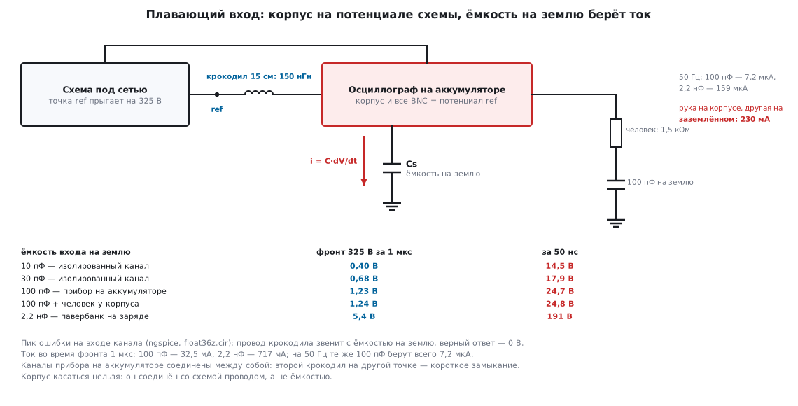
What the table shows. On the slow mains a floating instrument is honest: the steepest slope of a 325 V sine is 0.102 V/µs, and the triac edge is 3180 times steeper. On an edge, though, even an isolated channel with 10 pF shows 14.5 V of spike at its input where the truth is zero; a battery-powered instrument shows 24.7 V. A person at the case adds their own current (twice as much, 64.4 mA), but through the body resistance, so the peak barely changes. And a power bank that is connected to its charger at that moment stops floating: the charger's Y capacitor (2.2 nF, as in 36а.5) ties it to the mains, and on a 50 ns edge the spike reaches 191 V — no longer interference but a pulse that hurts the input.
🔧 If you use a battery-powered instrument anyway. One channel, one clip, and only on a point that does not jump itself (the circuit common, not the switch output). The instrument on an insulating stand, hands away before the mains is switched on, the power bank disconnected from its charger, USB to a computer — never. And above all — the instrument's specifications: if its inputs have no rating for floating measurements with a category (36з.7), it is not connected to mains at all.
36з.4 Several channels referenced to different points
These are two quite different cases, and confusing them is dangerous.
Phases of a multiphase converter relative to a common point. Three switch outputs of a three-phase inverter, two phases of a power factor corrector, four phases of a processor supply — all are measured relative to one common point: the bus minus. The clips of all channels go to that one point, the tips to the phases. The channels do not need different references, and an ordinary oscilloscope copes if the common point itself is earth (a low-voltage circuit) or the device is isolated by a transformer and the common point has become earth (36з.2). The rule is the same as in 36а.2: clips short and all on one point, without loops between them.
Two galvanically isolated parts. The primary and secondary of a flyback supply, the high-side switch of a half bridge and its driver, the mains and low-voltage sides of an optocoupler (54.6). Here the references really are different, and between them is the isolation barrier that you are actually testing. The clip of channel 1 on the primary and the clip of channel 2 on the secondary are a wire through the instrument chassis across the barrier: the insulation for which the millimetres of clearance were calculated (208.3) is shorted by the oscilloscope. Here you need either isolated channels, each with its own reference, or a differential probe for each side. A battery-powered instrument (36з.3) will not do: its channels are common.
The DHO900 channels are not isolated. The datasheet (p. 10) has the line "Channel-to-Channel Isolation ≥100:1", and it is easy to take it for isolation. It is something else: the ratio of a signal in its own channel to its leakage into the neighbouring one, that is, crosstalk. Galvanic isolation of the channels appears nowhere in the documents; on the contrary, the guide (p. 17) requires keeping the ground lead of every probe at earth and warns that a voltage on it reaches the connectors and the chassis. All four clips of the DHO900 are one common wire with the chassis.
36з.5 Two ordinary probes and A − B math: why it lies
The temptation is clear: two channels, both clips on PE and neither on the circuit, the tips on two points, and the screen shows the difference of the channels, the math function from 36е. The common mode will subtract out, leaving the useful difference. This is called a pseudo-differential measurement, and it lies for two reasons.
Different gain. Subtraction is exact only if both channels amplify
equally. A 1:10 probe is a divider with a tolerance, and each channel has its own spread
of gain; a difference of 1–2 % is quite normal. On the DHO900 the DC gain
accuracy is ±1 % at sensitivities coarser than 5 mV/div
and ±2 % (typical) at 5 mV/div and finer (datasheet, p. 10): two
channels that drift in opposite directions differ by up to 2 %, which is 6.5 V from the mains.
Then of a common mode
U the screen keeps δ·U:
| Gain spread between channels | Residue per 1 V of common mode | Common-mode rejection | From 325 V of mains |
|---|---|---|---|
| 1 % | 10 mV/V | 40.0 dB | 3.25 V |
| 2 % | 20 mV/V | 34.0 dB | 6.50 V |
The ngspice model (pseudo36z.cir, both tips on a 325 V 50 Hz sine, no
difference) shows the same 3.25 and 6.50 V on the screen. For comparison: the gate pulse
of a triac relative to its MT1 terminal is a few volts. The error is of the same
order as the signal.
On edges it is worse: the probe gain at high frequency is set not by the resistor divider but by its compensation (36а.2). Probes trimmed "by eye" on the calibrator square wave differ by tens of percent. In the model the second probe is trimmed to 12 pF instead of 11.1 pF: on an edge it divides by 0.1071 instead of 0.1000 — 7.14 % more. A 325 V edge in 1 µs on both tips produces a spike of 23.1 V on the A − B trace, which decays only over hundreds of microseconds (after 10 µs it is still −21.3 V).
The common mode clips the input. For the subtraction to work at all, both channels must pass the common mode without distortion. To fit ±325 V into the 8 divisions of the screen you need 81.25 V/div — in practice 100 V/div. An oscilloscope ADC is usually 8-bit: 800 V of full scale over 256 codes — 3.125 V per code. A pulse of a few volts is smaller than one code. The DHO900 has a 12-bit ADC over the same 8 divisions (datasheet, p. 10): 0.195 V per code — the pulse is now visible, but the error from the gain spread (volts) is still larger than it. Setting a higher sensitivity, say 2 V/div, is not possible: the window is ±8 V, the common mode is 41 times larger, the input amplifier goes into clipping, and the difference of two clipped signals is garbage, while the amplifier's recovery from overload takes a time that the specifications do not always state.
⚠️ A − B is not a substitute for a differential probe. It works when the common mode is small compared with the signal (hundreds of millivolts on a shunt in a low-voltage circuit), and the channels have first been matched on one signal. Under mains it gives an error the size of the signal itself — and the tips of ordinary probes on mains points also require a probe rating (36з.7).
36з.6 The differential probe and capacitance across the barrier
A differential probe is two identical dividers (arms) and a subtractor. Each arm, like a 1:10 probe, must be compensated: the arm resistor and its capacitance. As long as the arms are identical, the common mode is divided equally in them and subtracts out. A difference between the arms is the same trouble as in 36з.5, only smaller: the arms are matched at the factory rather than taken from two different channels.
Model (diff36z.cir): division 1:100, each arm is 4.95 MΩ ‖ 1 pF on top and
50 kΩ ‖ 99 pF below (equal time constants: 4.95 µs and 4.95 µs).
The second arm is worse by two small tolerances: the top resistor by 0.01 %,
the top capacitance by 0.01 pF (1 %). The subtractor in the model is ideal — a real
amplifier adds its own:
| Frequency | Common-mode rejection |
|---|---|
| 50 Hz | 80.0 dB |
| 1 kHz | 69.8 dB |
| 10 kHz | 50.6 dB |
| 100 kHz | 40.5 dB |
| 1 MHz | 40.1 dB |
| 10 MHz | 40.1 dB |
At low frequency the arm current flows through the resistors, and the rejection is set by their matching (0.01 % — 80 dB). As frequency rises the current moves into the capacitances, and the capacitance mismatch takes over: 1 % — 40 dB. The transition happens at hundreds of hertz to kilohertz, because the arm capacitance is only 1 pF against 4.95 MΩ. Hence the rule: read the common-mode rejection in the probe specifications at the frequency where your edge lives, not at 50 Hz.
In numbers for 325 V mains: at 50 Hz the residue at the input is 32.6 mV (model; calculation for 80 dB — 32.5 mV). A 325 V edge in 1 µs gives a 2.91 V spike, in 50 ns — 3.20 V: on the edge the capacitive limit of 40 dB is already at work (calculation: 3.25 V). Against 23.1 V for the two probes in 36з.5 this is almost eight times better — but not zero: a 3 V step on the screen after every triac turn-on is the probe, not the circuit.
Capacitance across the barrier. An isolated channel and a battery-powered
instrument have their own weakness, and 36з.3 has quantified it: the capacitance of the
floating part to earth. On every edge C·dV/dt flows through it, and
it flows through the reference lead — even 10 pF on a 325 V edge in 50 ns gives 65 mA
and a 14.5 V spike on the 150 nH of the clip. This is the same common-mode transient
immunity as for signal isolators (54.5), only for the instrument. What helps is
a short reference (a spring instead of the clip — less inductance),
a smaller barrier capacitance and a slower edge. A differential probe
has no reference clip at all, and its current through the arm capacitances — picofarads —
flows through the inputs, not through a common lead; so on fast edges it is
usually cleaner than an isolated channel, while on slow signals an isolated
channel is more accurate.
36з.7 CAT categories and the probe rating
The voltage on the probe body is not the only thing it has to withstand. The mains carries short surges — from lightning, from switching of neighbouring loads — of thousands of volts, and the closer the measurement point is to the building's service entrance, the stronger they are. That is why the rating of a measuring instrument and of a probe is written as a pair: category and voltage, for example "CAT II 300 V".
- CAT II — whatever plugs into an outlet: household appliances, mains power supplies, tools. Debugging a mains-powered device on the bench is here.
- CAT III — the fixed building installation: distribution boards, circuit breakers, wiring, stationary motors.
- CAT IV — the source: the service entrance, the electricity meter, the overhead line.
- Circuits not directly connected to the mains (a secondary, a battery) used to be marked CAT I; the current edition of IEC 61010 has no category I, but the "CAT I" marking is still found on older instruments.
The DHO900 is category I only. The guide (p. 19) explicitly allows it measurements in category I only, and the datasheet (p. 10) limits the channel input to 300 V rms and 400 V peak in category I, forbids transient overvoltages with or without a probe, and refers you to instruments intended for categories II–IV for those categories. So the DHO900 input itself is not connected to the mains even through a 1:10 probe (with 325 V of mains peak, the BNC would see 32.5 V — the issue is not the volts but the category and the clip on PE). Under mains it works only through an accessory that has its own CAT II rating for the required voltage — a differential probe. In the accessory list of the datasheet (p. 6) the high-voltage differential probes are given with bandwidth and maximum voltage but no category: you look it up in the documentation and on the body of the probe itself.
The voltage in a rating is the working voltage relative to earth, rms. A 230 V mains gives 230 V from line to earth and up to 253 V with a +10 % tolerance — this fits the "300 V" row. The impulses that an instrument of its category must withstand (from the IEC 60664-1 table; the standard is not in the project, the figures were not checked):
| Rating relative to earth | CAT II | CAT III | CAT IV |
|---|---|---|---|
| 300 V | 2.5 kV | 4 kV | 6 kV |
| 600 V | 4 kV | 6 kV | 8 kV |
| 1000 V | 6 kV | 8 kV | 12 kV |
Three rules follow from this:
- The rating of a chain is that of its weakest link. A CAT III 600 V probe on the input of a CAT II 300 V oscilloscope is CAT II 300 V. The same goes for adapters, clips and probe extensions.
- A probe may have two ratings. The rating of the tip and the rating of its common lead relative to earth can differ, the second being much lower. An ordinary passive oscilloscope probe is designed for its clip to be at earth; check the marking on the body and in the specifications.
- The rating falls with frequency. The allowed voltage of passive probes and inputs is specified at low frequency and decreases at high frequency — see the graph in the probe specifications.
A high category does not make a measurement safe if the probe is used for the wrong purpose: the clip of an ordinary probe on a mains point violates the very principle of 36з.1, whatever rating is printed on the tip.
36з.8 Example: a transformerless supply and a heater triac
The device: a 2000 W heater controller. The microcontroller supply is transformerless (a dropping capacitor or a small non-isolated switcher), and the circuit common is connected to the MT1 terminal of the triac and to one of the mains conductors. The zero is caught by a resistor detector of 1 MΩ straight onto the pin, the triac is turned on by a pulse of 200 µs, the 90° angle is a delay of 5000 µs from zero (208б.3–208б.6). The whole board lives on the mains; there is no isolation anywhere.
First — where the board "ground" points. An outlet with side earth contacts does not define where the line is: the plug can be turned over. So the circuit common is neutral in half of the insertions and line in the other half, and you must count the worst case: 325 V peak relative to PE. The clip of a mains-powered oscilloscope on this "minus" is either a short circuit from line to PE (hundreds of amperes, 208.7) or, if you are lucky with the plug, neutral to PE bypassing the RCD: part of the load current returns through PE, and the RCD trips. Neither is a measurement.
Step 1 — without mains. Everything that can be is debugged on the bench from a lab power supply (208.7): the zero-cross detector is fed from a generator through the same resistor, the gate pulse is viewed at the microcontroller pin with an ordinary probe — delay, a duration of 200 µs, stability of the angle. The SWD debugger is used only in this mode.
Step 2 — under mains, with differential probes. The oscilloscope is earthed (on the DHO900 — the rear-panel terminal to PE, 36з.1), the board goes through an RCD, one hand only. Four channels, each with its own differential probe rated at least CAT II 300 V:
| Channel | Probe plus | Probe minus | What to look at |
|---|---|---|---|
| 1 | line L | neutral N | the mains: the sine zero — the reference for the angle |
| 2 | zero-cross detector pin | board common | the detector threshold — in the 208б.4 model 16.1 µs after zero |
| 3 | triac gate | MT1 | a 200 µs pulse at a delay of 5000 µs (90°) |
| 4 | MT2 | MT1 | the triac voltage: drops at turn-on and stays down until the current zero |
The common mode for channels 2 and 3 is the board common, that is, the 50 Hz mains: slow (0.102 V/µs), and even 80 dB of rejection leaves 32.5 mV of it at the input — trivial against a gate pulse of a few volts. Channel 4 itself sees a fast edge (325 V in microseconds), but that is its difference, not the common mode. What to look for:
- the angle — the delay from the zero of channel 1 to the pulse of channel 3; if you take the zero from the detector edge (channel 2) instead of the middle of its pulse, the angle drifts (208б.4);
- latching — on channel 4 after the gate pulse ends the voltage must stay near zero until the end of the half cycle; if it returns to the mains level, the load current did not reach the latching current (208б.3), and the pulse is lengthened;
- the supply — a fifth question, which needs one more probe: the microcontroller supply voltage relative to the common at the moment of the gate pulse, and whether the dropper supply sags from the gate current.
Step 2 the other way — an isolation transformer. If you have no differential probes, the board is powered through a transformer, but a 2000 W heater requires a transformer of at least 2000 VA. Replacing the heater with a lamp changes the triac latching current, and latching on a lamp says nothing about the heater. Behind the transformer the clips of all channels go only to the board common (36з.2), and channel 1 (the mains) cannot be viewed without a differential probe.
⚠️ What not to do on this board. The clip of a mains-powered oscilloscope on the common; an oscilloscope without PE; USB or SWD to a computer under mains; a battery- or power-bank-powered instrument in your hand; the DHO900 input of category I straight on the mains (36з.7); two channels A − B instead of a differential probe on the gate pulse (36з.5: an error of 3.25 V from the mains at a 1 % spread).
36з.9 Your own differential probe
A factory differential probe is expensive, and the question "build one myself" comes up often. You can — but everything quantified in 36з.6 becomes your job: matching the arms to hundredths of a percent, arm capacitances to hundredths of a picofarad, an isolated supply for the subtractor, a divider rating for voltage and category, and verifying that all of it really is so. How this is done is the next section, 36и.
36з.10 Pitfalls
"I cut the ground off the oscilloscope — and everything works." It works because the chassis, all BNCs and all clips have risen to the potential of the circuit. Touching the chassis and something earthed means 230 mA through the body (36з.1, 208.1). Isolate the device or the channel, not the oscilloscope.
Battery-powered oscilloscope: the second channel went bang. Its channel clips are common: the second one on another point is a short circuit (36з.3). You need isolated channels or differential probes (36з.4).
A spike of tens of volts on every switch edge that is not there. The capacitance of the floating input to earth and the clip lead: 100 pF and a 50 ns edge — 24.7 V in the model, a power bank on charge — 191 V (36з.3). Remove the charger, shorten the reference, move to a differential probe.
A − B shows a mains sine of several volts where there is none. Gain spread between channels: 1 % — 10 mV for every volt of common mode, 3.25 V from the mains; on edges — probe compensation, 23.1 V in the model (36з.5).
The differential probe is clean on the mains, but there is a step on edges. Common-mode rejection falls with frequency: 80 dB at 50 Hz, 40 dB at megahertz in the model (36з.6). Read the probe specifications at the edge frequency.
An isolated channel, yet a spike on the edge. Barrier capacitance: 10 pF on a 50 ns edge — 65 mA through the reference lead and a 14.5 V spike (36з.3, 36з.6). A short reference, a slower edge or a differential probe.
Clip on the "minus" of a transformerless board — the RCD tripped. Lucky with the plug: the "minus" was neutral, and the load current returned through PE bypassing the RCD. With the plug the other way round it would have been a line-to-PE short (36з.8).
A probe marked CAT III on the input of a CAT II instrument. The rating of the chain is that of its weakest link (36з.7).
36з.11 Summary
- The oscilloscope ground is protective earth PE. On the DHO900 (12 V power over USB-C from an adapter) — the rear-panel terminal: connect it to PE and check with an ohmmeter.
- An oscilloscope without PE is dangerous: the chassis, all BNCs and the clips rise to the potential of the circuit; under mains that is 230 mA through the body. PE is not cut — you isolate the device or the channel.
- Three correct ways: an isolation transformer in front of the device under test (one common clip, the RCD does not work, power not less than the load), isolated channels, a differential probe.
- A battery-powered oscilloscope floats, but its channels are common, the chassis is at circuit potential, and the capacitance to earth draws current on edges: 100 pF — a 24.7 V spike on a 50 ns edge, a power bank on charge — 191 V.
- Phases relative to a common point — one clip for all; two isolated parts — isolated channels or one differential probe per side.
- A − B with two probes: 1–2 % spread — 10–20 mV per volt of common mode, 3.25–6.50 V from the mains; on edges — compensation, 23.1 V in the model; the common mode also drives the input into clipping.
- Differential probe: the common-mode rejection is set by the arms — 80 dB at 50 Hz, 40 dB at megahertz in the model; read it at the edge frequency.
- Category and voltage come as a pair, relative to earth; the rating of a chain is that of its weakest link; a bench with a mains-powered device is CAT II, 300 V.
- A transformerless board: the "minus" is line or neutral; first without mains, then with differential probes: mains, detector, gate, MT2 − MT1.
Full sources
float36z.cir — the floating input and its capacitance to earth: the spike on the clip lead.
* 36з.3, 36з.6: плавающий вход (осциллограф от аккумулятора или изолированный канал)
* и его ёмкость на землю. Крокодил сидит на точке ref, которая прыгает на 325 В
* (симистор открылся на вершине: фронт 1 мкс; ключ MOSFET: фронт 50 нс).
* Остриё смотрит на ту же точку — правильный ответ на экране 0 В.
* Ошибка на экране = V(ref) - V(ch): падение на проводе крокодила.
* Крокодил 15 см: 150 нГн и 0,05 Ом (как в 36а.2); выход точки — 1 Ом.
* Ёмкость входа на землю C: 10/30 пФ (изолированный канал), 100 пФ (прибор на
* аккумуляторе), 100 пФ + человек (1,5 кОм + 100 пФ, модель тела HBM),
* 2,2 нФ (павербанк заряжается: Y-конденсатор зарядника).
.subckt flt src ch c=100p
Rs src ref 1
Lg ref m 150n
Rg m ch 0.05
Cs ch 0 {c}
.ends
.subckt fltp src ch
Rs src ref 1
Lg ref m 150n
Rg m ch 0.05
Cs ch 0 100p
Rb ch b 1.5k
Cb b 0 100p
.ends
V1 s1 0 PULSE(0 325 1u 1u 1u 1 2)
V2 s2 0 PULSE(0 325 1u 50n 50n 1 2)
X11 s1 c11 flt c=10p
X12 s1 c12 flt c=30p
X13 s1 c13 flt c=100p
X14 s1 c14 fltp
X15 s1 c15 flt c=2.2n
X21 s2 c21 flt c=10p
X22 s2 c22 flt c=30p
X23 s2 c23 flt c=100p
X24 s2 c24 fltp
X25 s2 c25 flt c=2.2n
.tran 0.1n 4u 0 0.1n
.control
run
let e11 = abs(v(X11.ref) - v(c11))
let e12 = abs(v(X12.ref) - v(c12))
let e13 = abs(v(X13.ref) - v(c13))
let e14 = abs(v(X14.ref) - v(c14))
let e15 = abs(v(X15.ref) - v(c15))
let e21 = abs(v(X21.ref) - v(c21))
let e22 = abs(v(X22.ref) - v(c22))
let e23 = abs(v(X23.ref) - v(c23))
let e24 = abs(v(X24.ref) - v(c24))
let e25 = abs(v(X25.ref) - v(c25))
meas tran err_1us_10p MAX e11
meas tran err_1us_30p MAX e12
meas tran err_1us_100p MAX e13
meas tran err_1us_person MAX e14
meas tran err_1us_2n2 MAX e15
meas tran err_50n_10p MAX e21
meas tran err_50n_30p MAX e22
meas tran err_50n_100p MAX e23
meas tran err_50n_person MAX e24
meas tran err_50n_2n2 MAX e25
meas tran i_1us_10p AVG l.x11.lg#branch FROM=1.4u TO=1.9u
meas tran i_1us_100p AVG l.x13.lg#branch FROM=1.4u TO=1.9u
meas tran i_1us_person AVG l.x14.lg#branch FROM=1.4u TO=1.9u
meas tran i_1us_2n2 AVG l.x15.lg#branch FROM=1.4u TO=1.9u
.endc
.end
pseudo36z.cir — a "differential" from two ordinary probes: gain and compensation spread.
* 36з.5: «дифференциал» из двух обычных щупов 1:10: на экране CH1 - CH2.
* Оба острия на одной точке — общая (синфазная) часть есть, разности нет: правильный ответ 0.
* Щуп: R1 || C1 в наконечнике, вход прибора 1 МОм || 100 пФ (вместе с кабелем, 36а.2).
* A — эталон: 9 МОм, 11,111 пФ (точная компенсация).
* B1 — усиление ниже на 1 %: 9,10101 МОм (и C1 подстроен под него);
* B2 — ниже на 2 %: 9,20408 МОм; B3 — усиление точное, C1 = 12 пФ (компенсация «на глаз»).
* Синфазное: синус 325 В 50 Гц (сеть) и фронт 325 В за 1 мкс (симистор открылся).
.subckt probe tip out r1=9meg c1=11.111p
R1 tip out {r1}
C1 tip out {c1}
R2 out 0 1meg
C2 out 0 100p
.ends
Vs s 0 SIN(0 325 50)
XA  s a  probe
XB1 s b1 probe r1=9.10101meg c1=10.98901p
XB2 s b2 probe r1=9.20408meg c1=10.86474p
Vf f 0 PULSE(0 325 1u 1u 1u 1 2)
XFA f fa probe
XFB f fb probe c1=12p
.tran 2u 60m 20m 2u
.control
run
let d1 = 10 * (v(a) - v(b1))
let d2 = 10 * (v(a) - v(b2))
meas tran sin_d1_max MAX d1
meas tran sin_d2_max MAX d2
.endc
.control
reset
tran 1n 20u 0 1n
let d3 = 10 * (v(fa) - v(fb))
let ad3 = abs(d3)
meas tran step_d3_max MAX ad3
meas tran step_d3_at10u FIND d3 AT=10u
.endc
.end
diff36z.cir — a 1:100 differential probe: common-mode rejection versus frequency and on edges.
* 36з.6: дифференциальный щуп 1:100 — два плеча-делителя и идеальный вычитатель.
* Плечо: 4,95 МОм || 1 пФ сверху, 50 кОм || 99 пФ снизу (скомпенсировано: 4,95 мкс = 4,95 мкс).
* Плечо B хуже на два допуска: резистор +0,01 %, верхняя ёмкость +0,01 пФ (+1 %).
* CMRR плеч = (усиление разности 1/100) / (усиление синфазного).
* Сам вычитатель в модели идеален — реальный усилитель добавит своё.
.subckt arm in out rt=4.95meg ct=1p
Rt in out {rt}
Ct in out {ct}
Rb out 0 50k
Cb out 0 99p
.ends
Vcm c 0 DC 0 AC 1
XA c a arm
XB c b arm rt=4.95049500meg ct=1.01p
Vp p 0 DC 0 AC 0.5
Vn n 0 DC 0 AC -0.5
XDA p da arm
XDB n db arm
Vf f 0 PULSE(0 325 1u 1u 1u 1 2)
XFA f fa arm
XFB f fb arm rt=4.95049500meg ct=1.01p
Vg g 0 PULSE(0 325 1u 50n 50n 1 2)
XGA g ga arm
XGB g gb arm rt=4.95049500meg ct=1.01p
Vs s 0 SIN(0 325 50)
XSA s sa arm
XSB s sb arm rt=4.95049500meg ct=1.01p
.control
ac lin 1 50 50
let cm = mag(v(a) - v(b))
let dm = mag(v(da) - v(db))
print 20*log10(dm/cm)
ac dec 10 10 100meg
let cm = mag(v(a) - v(b))
let dm = mag(v(da) - v(db))
let cmrr = 20*log10(dm/cm)
meas ac cmrr_1k FIND cmrr AT=1k
meas ac cmrr_10k FIND cmrr AT=10k
meas ac cmrr_100k FIND cmrr AT=100k
meas ac cmrr_1meg FIND cmrr AT=1meg
meas ac cmrr_10meg FIND cmrr AT=10meg
meas ac dm_1k FIND dm AT=1k
tran 1n 6u 0 1n
let e1 = 100 * abs(v(fa) - v(fb))
let e2 = 100 * abs(v(ga) - v(gb))
meas tran step1us_err MAX e1
meas tran step50n_err MAX e2
tran 2u 60m 20m 2u
let e3 = 100 * (v(sa) - v(sb))
meas tran sin50_err MAX e3
.endc
.end
Next: section 36и "Your own differential probe: isolated amplifier, isolated power, divider and verification" — how to build a differential probe yourself: match the arms, isolate the subtractor supply and verify it.