 Embedded HandbookApps
22и. Port expander MCP23017 over I2C: 16 lines, interrupt-on-change, keypad and bounce
In section 22 pins were added with shift registers: the 74HC595 for
outputs (22.1), the 74HC165 for inputs (22.2). They are fast but deaf: the
direction of a line is fixed by the chip, and the program learns about a
pressed button only when it asks. The MCP23017 is an expander of another
kind: 16 lines, each one an input or an output on its own, with a pull-up,
with inversion and with an interrupt on change, all over the two I2C
wires. Here is how it is built, how to connect it to the STM32F103, why
outputs are changed through OLAT and not through GPIO, what INTCAP
is and why the interrupt can get "stuck", how to make a 4×4 keypad with
debouncing on one of its ports, and how much bus time it costs.
Sources: RM0008 (DocID13902 Rev 17): the pin mode table, p. 160;
AFIO_EXTICR3, p. 191; EXTI_FTSR and edge triggering, p. 211; I2C is
up to 100 kHz in standard mode and up to 400 kHz in fast mode, p. 752;
master reception of more than two bytes, p. 763, of one and two, p. 764;
I2C_CCR, p. 783–784; I2C_TRISE, p. 784. DocID13587 Rev 17
(STM32F103x8/xB): PB6 is I2C1_SCL, PB7 is I2C1_SDA, both FT, p. 32;
PB8 and PB9 are FT, p. 33; FT means 5 V tolerant, p. 33. The project has no
MCP23017 document. The register numbers, the MIRROR bit, the power-on
values, active-low INT and RESET, clearing the interrupt by reading
INTCAP and the 2 µs reset pulse were checked against the gpio_mcp23xxx
driver from Zephyr 4.4.2; the 0x20 address, the GPPU, GPIO and OLAT
numbers and the note "writing GPIO changes OLAT" against the QMK
keyboard drivers on disk. The other IOCON bits, the register map with
BANK = 1, how the register number moves with SEQOP and the interrupt
behavior follow the manufacturer's documentation and were not checked: in
the model they are assumptions. All numbers below come from running the
driver _verify/gpx22j/mcp22j.c on a computer (gcc 12.2.0) with its own
model of the MCP23017 as an I2C slave and of a bouncing keypad in
Python 3.11; the firmware is built with armclang 6.24 for the Cortex-M3.
What it is called in the documentation
Original Meaning I/O expander port expander IODIR (I/O direction) direction: 1 is input, 0 is output IPOL (input polarity) input inverted on read GPPU (pull-up) input pull-up to the supply OLAT (output latch) output latch: what was written GPIO (port register) levels on the pins: what is really there GPINTEN (interrupt-on-change enable) interrupt enable for a line DEFVAL, INTCON reference value and choice: on change or on difference from the reference INTF (interrupt flag) which line caused the interrupt INTCAP (interrupt captured value) snapshot of the port at the interrupt IOCON: BANK, MIRROR, SEQOP, ODR, INTPOL register layout, shared INT, register number auto-increment, open-drain INT, active level of INT ghosting false key press in a matrix debouncing bounce suppression
22и.1 The chip: two ports of eight lines
The MCP23017 has two ports, A and B, of eight lines each: GPA0…GPA7 and
GPB0…GPB7. Each port has its own set of ten registers plus the shared
IOCON; each has its own interrupt pin, INTA and INTB. The bus address is
0x20 plus three pins A2…A0. In the model jumpers 000 answered at 0x20 (the
byte on the line is 0x40 for writing and 0x41 for reading, 17.2), 001 at
0x21, 111 at 0x27 (0x4E and 0x4F): eight chips fit on one bus, 128 lines.
A foreign address gives MCP_E_NACK.
With BANK = 0 (as after power-on) the registers of the two ports are
interleaved: port A has an even number, port B the next one. Zephyr keeps
the numbers of the eight-line MCP23008 (from 0x00 to 0x0A) and for the
16-line chip multiplies them by two — the same table:
/* ── регистры при BANK = 0: у порта A чётный номер, у порта B — следующий ─ */
#define MCP_IODIRA    0x00u             /* 1 — вход, 0 — выход; после сброса 0xFF */
#define MCP_IPOLA     0x02u             /* 1 — читать вход инверсным */
#define MCP_GPINTENA  0x04u             /* 1 — линия может вызвать прерывание */
#define MCP_DEFVALA   0x06u             /* с чем сравнивать при INTCON = 1 */
#define MCP_INTCONA   0x08u             /* 0 — по изменению, 1 — по отличию от DEFVAL */
#define MCP_IOCON     0x0Au             /* один регистр на два номера: 0x0A и 0x0B */
#define MCP_GPPUA     0x0Cu             /* 1 — подтяжка к питанию на входе */
#define MCP_INTFA     0x0Eu             /* какая линия вызвала прерывание (только чтение) */
#define MCP_INTCAPA   0x10u             /* состояние порта в момент прерывания (только чтение) */
#define MCP_GPIOA     0x12u             /* чтение — уровни на выводах, запись — в OLAT */
#define MCP_OLATA     0x14u             /* защёлка выходов: что записано, а не что на выводе */
#define MCP_PORTB     1u                /* прибавить к номеру — регистр порта B */
/* ── при BANK = 1 порт A — 0x00…0x0A, порт B — 0x10…0x1A ─────────────── */
#define MCP_B1_IOCON  0x05u
#define MCP_B1_GPIOA  0x09u
#define MCP_B1_OLATA  0x0Au
| Register | A / B | What it does | After power-on |
|---|---|---|---|
IODIR |
0x00 / 0x01 | 1 is input, 0 is output | 0xFF — all inputs |
IPOL |
0x02 / 0x03 | 1 reads the input inverted | 0 |
GPINTEN |
0x04 / 0x05 | the line may cause an interrupt | 0 |
DEFVAL |
0x06 / 0x07 | reference for comparison | 0 |
INTCON |
0x08 / 0x09 | 0 on change, 1 on difference from DEFVAL |
0 |
IOCON |
0x0A and 0x0B | chip settings, one register at two numbers | 0 |
GPPU |
0x0C / 0x0D | input pull-up to the supply | 0 |
INTF |
0x0E / 0x0F | which line caused the interrupt | 0 |
INTCAP |
0x10 / 0x11 | snapshot of the port at the interrupt | 0 |
GPIO |
0x12 / 0x13 | read gives pin levels, write goes to OLAT |
— |
OLAT |
0x14 / 0x15 | output latch | 0 |
After power-on the model read IODIR = 0xFFFF and zeros in all the other
registers except GPIO; Zephyr writes the same values into its copy of
the registers "according to the datasheet". In IOCON, per the
manufacturer's documentation (not checked): bit 7 BANK is the layout,
bit 6 MIRROR makes INTA and INTB shared, bit 5 SEQOP stops the
register number from growing after a byte, bit 4 DISSLW is the SDA slew
rate, bit 3 HAEN is the address pins of the MCP23S17, the SPI sibling,
bit 2 ODR makes INT open drain, bit 1 INTPOL is the active level of
INT. Of these bits Zephyr has only MIRROR (bit 6).
Why this is better than the 74HC165 from 22.2: direction and pull-up are per line, the chip reports a press by itself, and the wires are the same two as for the I2C sensors. Why it is worse: every access is an I2C transaction of tens of microseconds (22и.6), not an SPI clock.
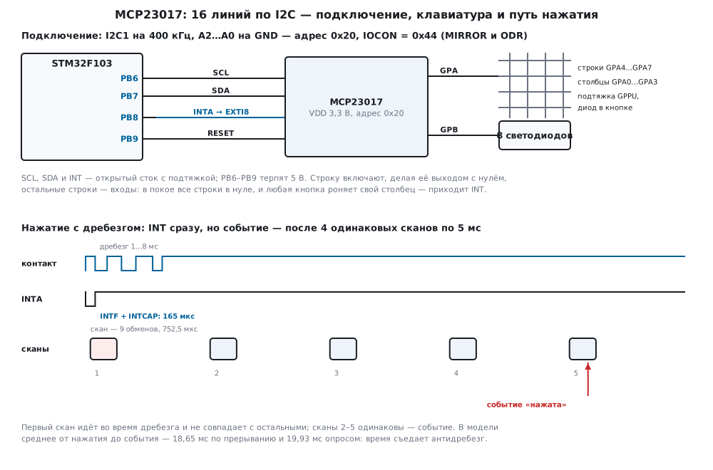
22и.2 Connecting to the F103: I2C1, INTA on EXTI, reset
| MCP23017 pin | STM32F103 | Purpose |
|---|---|---|
| SCL, SDA | PB6, PB7 | I2C1, 400 kHz |
| INTA | PB8 | falling edge is EXTI8; INT open drain (ODR = 1) |
| RESET | PB9 | zero resets the chip |
| A2, A1, A0 | GND | address 0x20 |
| VDD, VSS | 3.3 V and ground | ground shared with the microcontroller |
PB6 and PB7 are the I2C1 pins, both FT (DocID13587, p. 32), PB8 and PB9
are FT too (p. 33): if the expander runs from 5 V, pull-ups of SDA, SCL
and INT to 5 V will not burn them. I2C1 itself is as in 15б.2: fast
mode, 36 MHz / (3 × 30) = 400 kHz, TRISE = 11 (p. 783–784); the F103
cannot go above 400 kHz (p. 752). INT is set to open drain (ODR = 1), and
PB8 itself gives the pull-up — an input with pull-up, code 1000 in the
pin mode table (p. 160). MIRROR = 1 routes both ports to INTA, and one
wire is enough. RESET of the MCP23017 is active low (so Zephyr describes
it); Zephyr holds it at zero for 2 µs, and the firmware does the same.
Line EXTI8 is tied to port B with bits 3:0 of AFIO_EXTICR3 = 0001
(p. 191), the falling edge is enabled in EXTI_FTSR (p. 211):
static void pins_init(void)
{
    RCC->APB2ENR |= RCC_APB2ENR_IOPBEN | RCC_APB2ENR_AFIOEN;
    RCC->APB1ENR |= RCC_APB1ENR_I2C1EN;
    /* PB6, PB7 — альтернативная функция, открытый сток, 50 МГц (1111) */
    GPIOB->CRL = (GPIOB->CRL & 0x00FFFFFFu) | 0xFF000000u;
    /* PB8 — вход с подтяжкой (1000), PB9 — выход 2 МГц (0010), RESET отпущен */
    GPIOB->BSRR = 1u << 8 | 1u << 9;
    GPIOB->CRH = (GPIOB->CRH & ~0xFFu) | 0x28u;
}

static void i2c1_init(void)
{
    I2C1->CR1 = 0;                                      /* настраивать при PE = 0 */
    I2C1->CR2 = APB1_MHZ;
    I2C1->CCR = I2C_CCR_FS | 30u;                       /* DUTY = 0: 36 МГц / (3 × 30) = 400 кГц */
    I2C1->TRISE = APB1_MHZ * 300u / 1000u + 1u;         /* 300 нс × 36 МГц = 10,8 → 10 + 1 = 11 */
    I2C1->CR1 = I2C_CR1_PE;
}

static void exti_init(void)
{
    AFIO->EXTICR[2] = (AFIO->EXTICR[2] & ~0xFu) | 0x1u;    /* EXTI8 ← PB8 */
    EXTI->FTSR |= 1u << 8;
    EXTI->IMR |= 1u << 8;
    NVIC_EnableIRQ(EXTI9_5_IRQn);
}
The EXTI handler only sets a flag: an I2C exchange takes hundreds of microseconds and belongs in the main loop (7.7). EXTI triggers on an edge, not on a level (RM0008, p. 211) — this will matter in 22и.4.
22и.3 Writing and reading: OLAT, not GPIO; sequential mode and BANK
The first byte of a write is the register number, then the values; the
number grows after each byte (SEQOP = 0), so both ports are written and
read in one transaction: the port A number, then byte A and byte B.
Start-up. After a microcontroller reset the chip may have stayed in
BANK = 1 — for instance from the previous firmware, if its RESET was not
touched. Then number 0x0A is OLATA for it, and IOCON lives at number
0x05. The driver starts by writing zero to 0x05: with BANK = 1 that is
IOCON, with BANK = 0 it is GPINTENB, which is zero after start-up
anyway:
/* IOCON с проверкой. Если микросхема пережила сброс микроконтроллера с BANK = 1, номер 0x0A у неё —
 * OLATA, а IOCON — 0x05. Поэтому сначала 0 в 0x05: при BANK = 1 это IOCON (BANK станет 0), при
 * BANK = 0 — GPINTENB, который всё равно должен быть 0 после запуска. */
int mcp_init(mcp_t *d, uint8_t addr7, uint8_t iocon)
{
    uint8_t v;
    int rc;
    d->addr = addr7;
    d->xfers = d->errors = 0;
    iocon &= (uint8_t)~MCP_BANK;
    if ((rc = mcp_wr(d, MCP_B1_IOCON, 0x00u)) != MCP_OK)       /* заодно: отвечает ли кто-то по адресу */
        return rc;
    if ((rc = mcp_wr(d, MCP_IOCON, iocon)) != MCP_OK)
        return rc;
    if ((rc = mcp_rd(d, MCP_IOCON, &v)) != MCP_OK)
        return rc;
    if (v != iocon)
        return MCP_E_CHIP;                                      /* по адресу не MCP23017 или он не в BANK = 0 */
    d->iocon = iocon;
    return mcp_rd16(d, MCP_OLATA, &d->olat);                    /* копия защёлки — из самой микросхемы */
}
In the model mcp_init(&dev, 0x20, 0x44) is 4 transfers: 05 00, 0A 44,
reading IOCON (0x44) and reading both OLAT (00 00); 1450 µs on the
bus at 100 kHz and 362.5 µs at 400 kHz. A naive start — 0x44 straight into
0x0A and a check by reading the same number — with BANK = 1 left over
also read 0x44 and decided all was well. In fact IOCON stayed 0x80, and
0x44 went into OLATA. From then on everything misses: number 0x12, which
the driver takes for GPIOA, is GPINTENB with BANK = 1, reads as zero,
and a keypad scan with one pressed button 5 returned 0xFFFF — all 16
pressed. With the write to 0x05 the same start gave IOCON = 0x44,
OLATA = 0x00 and a scan of 0x0020 — button 5.
Outputs go through a copy of OLAT. Reading GPIO returns the levels
on the pins, not what was written. On an overloaded output — an LED
without a resistor, a capacitance, a foreign output on the same line — the
level may differ from the latch. An experiment in the model: port B is
outputs, B7 = 1, but a load holds it at zero. We turn on B0 "the usual
way": read GPIO, set the bit, write to GPIO. The read returned 0x00,
the write put 0x01 into OLATB instead of 0x81: B7 is off for good, and
when the load was removed it stayed at zero. That took 2 transfers,
215 µs at 400 kHz. The driver keeps a copy of OLAT in memory and writes
only the latch — 1 transfer, 72.5 µs, OLATB = 0x81:
/* Выходы меняются по копии OLAT: чтение GPIO вернуло бы уровни на выводах, а не то, что записано. */
int mcp_set(mcp_t *d, uint16_t mask, uint16_t val)
{
    uint16_t n = (uint16_t)((d->olat & ~mask) | (val & mask));
    int rc;
    if ((mask & 0xFF00u) && (mask & 0x00FFu))
        rc = mcp_wr16(d, MCP_OLATA, n);
    else if (mask & 0xFF00u)
        rc = mcp_wr(d, MCP_OLATA + MCP_PORTB, (uint8_t)(n >> 8));
    else
        rc = mcp_wr(d, MCP_OLATA, (uint8_t)n);
    if (rc == MCP_OK)
        d->olat = n;
    return rc;
}
QMK says it right in its register numbers: writing GPIO changes OLAT.
Zephyr does not read GPIO before writing either — it changes a bit in
its own copy.
Sequential mode and BANK. Reading four bytes from 0x12 (port A is
inputs with pull-up, 0xFF; port B is outputs, 0x5A) gave in the model:
IOCON |
Number | Four bytes | What was read |
|---|---|---|---|
| 0x00 | 0x12 | FF 5A 00 5A | GPIOA, GPIOB, OLATA, OLATB |
0x20 (SEQOP) |
0x12 | FF 5A FF 5A | the number moves inside the A/B pair |
0xA0 (BANK, SEQOP) |
0x09 | FF FF FF FF | the number stays: GPIOA again and again |
This behavior follows the manufacturer's documentation and is an
assumption in the model. The last mode is useful for frequent samples of
one port: one transaction of 16 bytes took 435 µs, 27.2 µs per sample,
against 97.5 µs for a separate read. The driver of this section works with
BANK = 0 and SEQOP = 0.
22и.4 Interrupts: on change, on DEFVAL, INTCAP and MIRROR
A line with GPINTEN = 1 causes a port interrupt: with INTCON = 0 when
its level changes, with INTCON = 1 while it differs from DEFVAL. When
it fires, the port records the line in INTF, the levels of the whole
port at that moment in INTCAP, and holds INT until its GPIO or INTCAP
is read. While INT is held, new changes are not recorded. Zephyr clears
the interrupt by reading INTCAP; the rest follows the manufacturer's
documentation and is an assumption in the model.
An experiment in the model, keypad idle (rows at zero, columns with
pull-up and GPINTEN): button 0 pressed — INTA fell, INTF = 0x01,
INTCAP = 0x0E, GPIO = 0x0E (column 0 at zero). Before the read button 0
was released and button 1 pressed: GPIO is already 0x0D, while INTCAP
is still 0x0E — a snapshot of the moment of the first change. Reading
INTF and INTCAP in one transaction returned 0x0001 and 0x000E, and INTA
was released. The release dropped INTA again (INTF = 0x02), and reading
GPIOA (0x0F) cleared it again. INTFA, INTFB, INTCAPA and INTCAPB
lie in a row — the driver takes them as four bytes:
/* INTFA, INTFB, INTCAPA, INTCAPB лежат подряд с 0x0E: четыре байта одной транзакцией.
 * Чтение INTCAP снимает прерывание. */
int mcp_irq(mcp_t *d, uint16_t *intf, uint16_t *intcap)
{
    uint8_t b[4];
    int rc = xfer_done(d, mcp_port_read(d->addr, MCP_INTFA, b, 4));
    if (rc == MCP_OK) {
        *intf = (uint16_t)(b[0] | b[1] << 8);
        *intcap = (uint16_t)(b[2] | b[3] << 8);
    }
    return rc;
}
Comparison with DEFVAL. With INTCON = 0x0F and DEFVAL = 0x0F
(idle columns are ones) an interrupt means "not idle" rather than
"changed". While button 11 is held, reading INTCAP (INTF = 0x0008,
INTCAP = 0x0007) clears the interrupt, and it rises again at once: after
three reads INTA is still at zero, the interrupt rose 3 times. Released —
the next read released INTA. INT stays at zero for the whole hold, and
EXTI on the falling edge sees one interrupt per press. Zephyr says it
plainly: the MCP23017 does not tell a single edge apart in hardware, and
the driver separates "press" and "release" by itself using INTCAP.
MIRROR, ODR, INTPOL. An event on input B0 with IOCON = 0x04
dropped only INTB, with 0x44 both INTA and INTB. INT levels in the model:
IOCON |
INT idle | INT on interrupt |
|---|---|---|
| 0x00 | 1 (push-pull) | 0 |
0x02 (INTPOL) |
0 | 1 |
0x04 (ODR) |
released | 0 |
0x06 (ODR and INTPOL) |
released | 0 |
With ODR = 1 the active level is zero for any INTPOL. Open drain is
needed when the INT pins of several chips are tied to one pin: the
push-pull output of the idle one holds a one against its neighbor's zero.
22и.5 A 4×4 keypad on one port: scan, debouncing, ghosts
The matrix is as in 22.5, only on port A of the expander: columns
GPA0…GPA3 are inputs with the GPPU pull-up, rows GPA4…GPA7 have zero in
OLAT. A row is "switched on" by making it an output, the other rows are
inputs: an inactive row is released, like the open drain in 22.5. A scan is
4 pairs of "write IODIRA, read GPIOA" plus returning all rows to zero,
9 transfers:
/* Один скан: 4 строки по очереди, на каждую — запись IODIRA и чтение GPIOA; в конце все строки снова
 * выходы с нулём. raw: бит 4 × строка + столбец, 1 — нажата. */
int kp_scan(mcp_t *d, uint16_t *raw)
{
    uint16_t keys = 0;
    uint8_t v;
    int rc;
    for (uint32_t r = 0; r < 4u; r++) {
        uint8_t dir = (uint8_t)(0xFFu & ~(0x10u << r));          /* выход — только строка r */
        if ((rc = mcp_wr(d, MCP_IODIRA, dir)) != MCP_OK)
            return rc;
        if ((rc = mcp_rd(d, MCP_GPIOA, &v)) != MCP_OK)
            return rc;
        keys |= (uint16_t)((~v & KP_COLS) << (4u * r));          /* нажатая кнопка — ноль на столбце */
    }
    if ((rc = mcp_wr(d, MCP_IODIRA, KP_COLS)) != MCP_OK)
        return rc;
    *raw = keys;
    return MCP_OK;
}
Bounce. The keypad model presses 100 buttons in 43.3 s; every press and release bounces for 1.00 to 7.98 ms: the contact switches every 50…1000 µs (a model assumption, the order as in 8.5). Scanning every 5 ms without any processing — every change of the raw scan counts as an event — gave 7 extra presses per 100: the scan hit a contact rebound. Debouncing accepts a new state when 4 scans in a row are identical — that is at least 15 ms without changes:
/* Антидребезг: новое состояние принимается, когда KP_STABLE сканов подряд одинаковы.
 * Возвращает 1, если принятое состояние сменилось; down и up — какие кнопки нажаты и отпущены. */
int kp_debounce(kp_t *k, uint16_t raw, uint16_t *down, uint16_t *up)
{
    uint16_t ch;
    *down = *up = 0;
    if (raw == k->last) {
        if (k->same < KP_STABLE)
            k->same++;
    } else {
        k->last = raw;
        k->same = 1;
    }
    if (k->same < KP_STABLE || raw == k->stable)
        return 0;
    ch = (uint16_t)(raw ^ k->stable);
    *down = (uint16_t)(ch & raw);
    *up = (uint16_t)(ch & k->stable);
    k->stable = raw;
    return 1;
}
With it there are 0 extra presses out of 100, and from the press to the event it takes 19.93 ms on average, from 15.43 to 27.91 ms (22и.6).
Ghosts and diodes. The driver scan over all sets of pressed buttons without diodes: pairs give 0 errors out of 120, triples 144 out of 560, exactly as in 22.5; buttons 0, 1 and 4 also showed 5. Quadruples give 1152 errors out of 1820. With a diode in every button (current only from the column into the row) there are 0 errors for pairs, triples and quadruples.
22и.6 Bus time and reaction: interrupt versus polling
SCL clocks per transaction in the model: a byte is 9 clocks, start, repeated start and stop are one each; no gaps between bytes (an assumption):
| Transfer | SCL clocks | 100 kHz | 400 kHz |
|---|---|---|---|
| writing one register | 29 | 290 µs | 72.5 µs |
| reading one register | 39 | 390 µs | 97.5 µs |
reading both ports (GPIOA and GPIOB) |
48 | 480 µs | 120 µs |
INTF and INTCAP of both ports |
66 | 660 µs | 165 µs |
| keypad scan, 9 transfers | 301 | 3010 µs | 752.5 µs |
A scan every 5 ms keeps the bus busy for 60.2 % at 100 kHz and 15.05 % at
400 kHz. The interrupt mode removes scans while nothing is pressed: when
idle all rows are at zero, the first touch drops a column, INT calls a
keypad step, and then scans run every 5 ms until everything is released
and settled. At the end the driver reads GPIOA: the scans toggled the
columns themselves and could have set INT again.
/* Шаг клавиатуры: вызывать раз в KP_SCAN_MS, а в режиме прерываний ещё и по спаду INT (irq = 1).
 * В режиме прерываний в покое шина молчит: шаг без irq сразу возвращает KP_IDLE. */
int kp_step(mcp_t *d, kp_t *k, int irq, uint16_t *down, uint16_t *up)
{
    uint16_t raw, f, cap;
    uint8_t v;
    int rc;
    *down = *up = 0;
    if (k->use_irq && !k->active) {
        if (!irq)
            return KP_IDLE;
        if ((rc = mcp_irq(d, &f, &cap)) != MCP_OK)              /* что случилось — и снять прерывание */
            return rc;
        k->active = 1;
    }
    if ((rc = kp_scan(d, &raw)) != MCP_OK)
        return rc;
    (void)kp_debounce(k, raw, down, up);
    if (k->use_irq && k->stable == 0u && raw == 0u && k->same >= KP_STABLE) {
        /* всё отпущено и устоялось: сканы сами дёргали столбцы и могли снова поставить INT — снять его,
         * и если столбцы все в единице, вернуться в покой */
        if ((rc = mcp_rd(d, MCP_GPIOA, &v)) != MCP_OK)
            return rc;
        if ((v & KP_COLS) == KP_COLS)
            k->active = 0;
    }
    return k->use_irq && !k->active ? KP_IDLE : KP_ACTIVE;
}
In the firmware the main loop calls the step: on the EXTI flag while the keypad is idle, and every 5 ms on SysTick while scans are running:
    for (;;) {
        int irq, rc, due = (int32_t)(ms - next) >= 0;
        if (kp.active ? !due : !irq_flag) {
            __WFI();                                    /* SysTick или EXTI разбудят */
            continue;
        }
        __disable_irq();
        irq = irq_flag;
        irq_flag = 0;
        __enable_irq();
        if (!kp.active)
            next = ms;                                  /* первый скан — сразу по INT */
        next += KP_SCAN_MS;
        rc = kp_step(&mcp, &kp, irq, &down, &up);
        if (rc < 0)
            bus_errors++;
        if (down) {
            uint16_t key = 0;
            while (!(down >> key & 1u))
                key++;
            presses++;
            (void)mcp_set(&mcp, 0xFF00u, (uint16_t)((key + 1u) << 8));
        }
    }
The same 100 presses at 400 kHz:
| Method | Extra presses | First sign of a press: mean / worst | From press to event: mean (from … to) | Transfers per second | Bus |
|---|---|---|---|---|---|
| polling, no debouncing | 7 | 4.48 / 11.78 ms | 4.83 ms (0.43 … 12.02) | 1800 | 15.05 % |
| polling, debouncing | 0 | 4.48 / 12.32 ms | 19.93 ms (15.43 … 27.91) | 1800 | 15.05 % |
| interrupt, debouncing | 0 | 0.17 / 0.17 ms | 18.65 ms (16.67 … 26.67) | 853 | 7.16 % |
With the interrupt the program learns about a touch after 0.17 ms — that
is the read of INTF and INTCAP — while polling takes 4.48 ms on
average. But the "pressed" event waits for four identical scans in both
cases, and the interrupt gains 1.28 ms on average: debouncing eats the
time. The main gain is elsewhere — the bus is silent when idle. Over these
43.3 s the interrupt mode made 36 756 transfers instead of 77 886.
22и.7 Pitfalls
The interrupt came once and never again. INT is held until GPIO or
INTCAP is read; reading INTF alone does not clear it. EXTI catches an
edge (RM0008, p. 211), and there is no more edge. In the model a button on
B0 is pressed 10 times: a program that reads only INTF on the falling
edge saw 1 interrupt and 1 press out of 10, INTA stayed at zero. A program
that reads INTF and INTCAP saw all 10 — and 164 interrupts: bounce
drops INT many times per press, so debouncing is needed here too.
One button is pressed, but all sixteen are read. The chip survived a
microcontroller reset with BANK = 1, and the driver writes and reads the
wrong registers (22и.3). The first write is 0 to 0x05, IOCON is checked
by reading, and better still a pulse on RESET at start-up.
An output turned itself off. The output was changed by reading GPIO:
the level of the overloaded pin got into OLAT (22и.3). Write to OLAT
from your own copy.
The chip answers now and then. Pin A0 is not connected. In the model a floating A0 reads randomly in every transaction, and 494 out of 1000 transfers to address 0x20 went unanswered. A2…A0 go only to GND or the supply. According to the manufacturer's documentation RESET also has to be held by a resistor to the supply if it does not go to the microcontroller (not checked).
The inputs show garbage. No pull-up: after power-on GPPU = 0, and a
released button leaves the input floating. Enable GPPU on the columns or
fit resistors.
Two chips on one INT get in each other's way. After power-on INT is
push-pull: when idle one holds a one, the other pulls zero. ODR = 1 and
one pull-up per line.
Microcontroller pins under 5 V. An expander at 5 V pulls SDA, SCL and INT up to 5 V. PB6–PB9 tolerate it (FT, DocID13587, p. 32–33), pins without FT do not; the supply range of the MCP23017 follows the manufacturer's documentation and was not checked.
Extra presses. A scan without debouncing gives 7 extra per 100 (22и.5).
A false button with three pressed. No diodes — 144 errors out of 560 triples.
The firmware "hung" in a transfer. The slave holds SDA after a failure
in the middle of a byte — BUSY does not clear. Bus recovery is in 17.6.
22и.8 Summary
- MCP23017: 16 lines in two ports, address 0x20 + A2…A0 (up to 8 chips on
a bus); with
BANK= 0 the registers of ports A and B go in pairs, from 0x00 to 0x15; after power-onIODIR= 0xFF, the rest is 0. - Connecting to the F103: I2C1 on PB6/PB7, 400 kHz; INTA on PB8 — EXTI8 on
the falling edge; RESET is PB9;
IOCON= 0x44 —MIRRORand open-drain INT. - Start-up is 4 transfers, 362.5 µs: first 0 to 0x05 in case of
BANK= 1, otherwise a scan with one button shows 0xFFFF. - Outputs go through a copy of
OLAT: 1 transfer, 72.5 µs; through readingGPIOit is 2 transfers, 215 µs, and an overloaded output loses its bit. INTCAPis a snapshot of the port at the interrupt; INT is cleared by readingINTCAPorGPIO, notINTF: without it 1 press out of 10, with it 10 out of 10 and 164 interrupts from bounce.- Keypad: a scan is 9 transfers, 301 clocks: 752.5 µs at 400 kHz, 15.05 % of the bus with a scan every 5 ms (60.2 % at 100 kHz); debouncing over 4 scans removes 7 extra presses out of 100.
- With the interrupt a touch is seen after 0.17 ms, but the event comes after 18.65 ms against 19.93 ms with polling: the gain is a silent bus, 853 transfers per second instead of 1800.
- Without diodes 144 false triples out of 560, with diodes 0.
Full sources
mcp22j.h — registers, IOCON bits, the port, the driver and the keypad: types and prototypes.
/* mcp22j.h — раздел 22и: драйвер расширителя портов MCP23017 (16 линий по I2C) и клавиатура 4×4 на его
 * порту A, без регистров микроконтроллера. Драйвер говорит с микросхемой через функции порта mcp_port_*:
 * в прошивке fw22j.c их делает I2C1 STM32F103, в стенде host22j.c — модель model22j.py.
 * Номера регистров при BANK = 0, бит MIRROR и сброс INTCAP чтением совпадают с драйверами Zephyr
 * (gpio_mcp23xxx.h) и QMK; остальные биты IOCON, карта при BANK = 1 и поведение прерываний — по
 * документации производителя, не проверено: документа в проекте нет. */
#ifndef MCP22J_H
#define MCP22J_H
#include <stdint.h>

/* ── регистры при BANK = 0: у порта A чётный номер, у порта B — следующий ─ */
#define MCP_IODIRA    0x00u             /* 1 — вход, 0 — выход; после сброса 0xFF */
#define MCP_IPOLA     0x02u             /* 1 — читать вход инверсным */
#define MCP_GPINTENA  0x04u             /* 1 — линия может вызвать прерывание */
#define MCP_DEFVALA   0x06u             /* с чем сравнивать при INTCON = 1 */
#define MCP_INTCONA   0x08u             /* 0 — по изменению, 1 — по отличию от DEFVAL */
#define MCP_IOCON     0x0Au             /* один регистр на два номера: 0x0A и 0x0B */
#define MCP_GPPUA     0x0Cu             /* 1 — подтяжка к питанию на входе */
#define MCP_INTFA     0x0Eu             /* какая линия вызвала прерывание (только чтение) */
#define MCP_INTCAPA   0x10u             /* состояние порта в момент прерывания (только чтение) */
#define MCP_GPIOA     0x12u             /* чтение — уровни на выводах, запись — в OLAT */
#define MCP_OLATA     0x14u             /* защёлка выходов: что записано, а не что на выводе */
#define MCP_PORTB     1u                /* прибавить к номеру — регистр порта B */
/* ── при BANK = 1 порт A — 0x00…0x0A, порт B — 0x10…0x1A ─────────────── */
#define MCP_B1_IOCON  0x05u
#define MCP_B1_GPIOA  0x09u
#define MCP_B1_OLATA  0x0Au

/* ── IOCON ────────────────────────────────────────────────────────────── */
#define MCP_BANK      0x80u             /* 1 — регистры портов раздельно */
#define MCP_MIRROR    0x40u             /* 1 — INTA и INTB сигналят о любом порте */
#define MCP_SEQOP     0x20u             /* 1 — номер регистра после байта не растёт */
#define MCP_DISSLW    0x10u
#define MCP_HAEN      0x08u             /* для MCP23S17 (SPI); у MCP23017 адрес задают A2…A0 всегда */
#define MCP_ODR       0x04u             /* 1 — INT открытый сток */
#define MCP_INTPOL    0x02u             /* активный уровень INT при ODR = 0: 0 — ноль */

#define MCP_ADDR_BASE 0x20u             /* A2…A0 на GND; 0x20…0x27 */
#define MCP_RESET_US  2u                /* RESET в нуле — столько держит драйвер Zephyr */

enum { MCP_OK = 0, MCP_E_NACK = -1, MCP_E_BUS = -2, MCP_E_CHIP = -3 };

typedef struct {
    uint8_t addr;                       /* семибитный адрес: 0x20 + A2…A0 */
    uint8_t iocon;                      /* что записано в IOCON */
    uint16_t olat;                      /* копия OLAT: порт A — младший байт, B — старший */
    uint32_t xfers, errors;             /* обменов по I2C и ошибок */
} mcp_t;

/* ── порт: в прошивке — I2C1, в стенде — строки к модели ──────────────── */
/* записать n байт одной транзакцией: START, адрес, байты, STOP; первый байт — номер регистра */
int mcp_port_write(uint8_t addr7, const uint8_t *tx, uint32_t n);
/* прочитать n байт с регистра reg: запись номера, повторный старт, чтение, STOP */
int mcp_port_read(uint8_t addr7, uint8_t reg, uint8_t *rx, uint32_t n);
void mcp_port_delay_us(uint32_t us);

/* ── драйвер ──────────────────────────────────────────────────────────── */
int mcp_wr(mcp_t *d, uint8_t reg, uint8_t v);
int mcp_wr16(mcp_t *d, uint8_t reg, uint16_t v);           /* порт A, потом B — одной транзакцией */
int mcp_rd(mcp_t *d, uint8_t reg, uint8_t *v);
int mcp_rd16(mcp_t *d, uint8_t reg, uint16_t *v);
int mcp_init(mcp_t *d, uint8_t addr7, uint8_t iocon);
int mcp_set(mcp_t *d, uint16_t mask, uint16_t val);        /* выходы: чтение-модификация-запись по копии OLAT */
int mcp_irq(mcp_t *d, uint16_t *intf, uint16_t *intcap);   /* INTF и INTCAP одной транзакцией — прерывание снято */

/* ── клавиатура 4×4 на порту A: столбцы GPA0…GPA3 — входы с подтяжкой, строки GPA4…GPA7 ── */
#define KP_COLS       0x0Fu
#define KP_ROWS       0xF0u
#define KP_SCAN_MS    5u                /* шаг сканирования */
#define KP_STABLE     4u                /* столько одинаковых сканов подряд — состояние принято */
#define KP_SCAN_XFERS 9u                /* обменов на один скан: 4 × (IODIR + GPIO) + возврат строк */

typedef struct {
    uint16_t stable;                    /* принятое состояние: бит 4 × строка + столбец */
    uint16_t last;                      /* прошлый скан */
    uint8_t same;                       /* сколько сканов подряд last не менялся */
    uint8_t use_irq;                    /* 1 — в покое ждать INT, 0 — сканировать всегда */
    uint8_t active;                     /* режим прерываний: идут сканы */
} kp_t;

enum { KP_IDLE = 0, KP_ACTIVE = 1 };

int kp_init(mcp_t *d, kp_t *k, int use_irq);
int kp_scan(mcp_t *d, uint16_t *raw);
int kp_debounce(kp_t *k, uint16_t raw, uint16_t *down, uint16_t *up);
int kp_step(mcp_t *d, kp_t *k, int irq, uint16_t *down, uint16_t *up);

#endif
mcp22j.c — the MCP23017 driver and the 4×4 keypad with debouncing, shared by the firmware and the bench.
/* mcp22j.c — раздел 22и: драйвер MCP23017 и клавиатура 4×4. Один и тот же файл собирается в прошивку
 * (armclang, Cortex-M3) и в стенд на компьютере (gcc): микроконтроллера он не знает, только порт mcp_port_*. */
#include "mcp22j.h"

static int xfer_done(mcp_t *d, int rc)
{
    d->xfers++;
    if (rc)
        d->errors++;
    return rc;
}

int mcp_wr(mcp_t *d, uint8_t reg, uint8_t v)
{
    uint8_t b[2] = {reg, v};
    return xfer_done(d, mcp_port_write(d->addr, b, 2));
}

int mcp_wr16(mcp_t *d, uint8_t reg, uint16_t v)
{
    uint8_t b[3] = {reg, (uint8_t)v, (uint8_t)(v >> 8)};    /* SEQOP = 0: номер растёт, A → B */
    return xfer_done(d, mcp_port_write(d->addr, b, 3));
}

int mcp_rd(mcp_t *d, uint8_t reg, uint8_t *v)
{
    return xfer_done(d, mcp_port_read(d->addr, reg, v, 1));
}

int mcp_rd16(mcp_t *d, uint8_t reg, uint16_t *v)
{
    uint8_t b[2];
    int rc = xfer_done(d, mcp_port_read(d->addr, reg, b, 2));
    if (rc == MCP_OK)
        *v = (uint16_t)(b[0] | b[1] << 8);
    return rc;
}

/* IOCON с проверкой. Если микросхема пережила сброс микроконтроллера с BANK = 1, номер 0x0A у неё —
 * OLATA, а IOCON — 0x05. Поэтому сначала 0 в 0x05: при BANK = 1 это IOCON (BANK станет 0), при
 * BANK = 0 — GPINTENB, который всё равно должен быть 0 после запуска. */
int mcp_init(mcp_t *d, uint8_t addr7, uint8_t iocon)
{
    uint8_t v;
    int rc;
    d->addr = addr7;
    d->xfers = d->errors = 0;
    iocon &= (uint8_t)~MCP_BANK;
    if ((rc = mcp_wr(d, MCP_B1_IOCON, 0x00u)) != MCP_OK)       /* заодно: отвечает ли кто-то по адресу */
        return rc;
    if ((rc = mcp_wr(d, MCP_IOCON, iocon)) != MCP_OK)
        return rc;
    if ((rc = mcp_rd(d, MCP_IOCON, &v)) != MCP_OK)
        return rc;
    if (v != iocon)
        return MCP_E_CHIP;                                      /* по адресу не MCP23017 или он не в BANK = 0 */
    d->iocon = iocon;
    return mcp_rd16(d, MCP_OLATA, &d->olat);                    /* копия защёлки — из самой микросхемы */
}

/* Выходы меняются по копии OLAT: чтение GPIO вернуло бы уровни на выводах, а не то, что записано. */
int mcp_set(mcp_t *d, uint16_t mask, uint16_t val)
{
    uint16_t n = (uint16_t)((d->olat & ~mask) | (val & mask));
    int rc;
    if ((mask & 0xFF00u) && (mask & 0x00FFu))
        rc = mcp_wr16(d, MCP_OLATA, n);
    else if (mask & 0xFF00u)
        rc = mcp_wr(d, MCP_OLATA + MCP_PORTB, (uint8_t)(n >> 8));
    else
        rc = mcp_wr(d, MCP_OLATA, (uint8_t)n);
    if (rc == MCP_OK)
        d->olat = n;
    return rc;
}

/* INTFA, INTFB, INTCAPA, INTCAPB лежат подряд с 0x0E: четыре байта одной транзакцией.
 * Чтение INTCAP снимает прерывание. */
int mcp_irq(mcp_t *d, uint16_t *intf, uint16_t *intcap)
{
    uint8_t b[4];
    int rc = xfer_done(d, mcp_port_read(d->addr, MCP_INTFA, b, 4));
    if (rc == MCP_OK) {
        *intf = (uint16_t)(b[0] | b[1] << 8);
        *intcap = (uint16_t)(b[2] | b[3] << 8);
    }
    return rc;
}

/* Столбцы — входы с подтяжкой и прерыванием по изменению; строки — выходы с нулём в OLAT.
 * Строку «включают», делая её выходом (IODIR = 0), остальные строки — входы без подтяжки: так
 * неактивная строка не держит единицу, и две кнопки в одном столбце не замыкают выход на выход.
 * В покое все строки — выходы с нулём: любая нажатая кнопка роняет свой столбец, и приходит INT. */
int kp_init(mcp_t *d, kp_t *k, int use_irq)
{
    int rc;
    k->stable = k->last = 0;
    k->same = 0;
    k->use_irq = (uint8_t)(use_irq != 0);
    k->active = 0;
    if ((rc = mcp_set(d, KP_ROWS, 0x00u)) != MCP_OK)
        return rc;
    if ((rc = mcp_wr(d, MCP_GPPUA, KP_COLS)) != MCP_OK)
        return rc;
    if ((rc = mcp_wr(d, MCP_IODIRA, KP_COLS)) != MCP_OK)        /* все строки — выходы с нулём */
        return rc;
    if ((rc = mcp_wr(d, MCP_INTCONA, 0x00u)) != MCP_OK)         /* по изменению, DEFVAL не нужен */
        return rc;
    if ((rc = mcp_wr(d, MCP_GPINTENA, use_irq ? KP_COLS : 0x00u)) != MCP_OK)
        return rc;
    {
        uint8_t v;
        return mcp_rd(d, MCP_GPIOA, &v);                        /* снять прерывание, если оно уже стоит */
    }
}

/* Один скан: 4 строки по очереди, на каждую — запись IODIRA и чтение GPIOA; в конце все строки снова
 * выходы с нулём. raw: бит 4 × строка + столбец, 1 — нажата. */
int kp_scan(mcp_t *d, uint16_t *raw)
{
    uint16_t keys = 0;
    uint8_t v;
    int rc;
    for (uint32_t r = 0; r < 4u; r++) {
        uint8_t dir = (uint8_t)(0xFFu & ~(0x10u << r));          /* выход — только строка r */
        if ((rc = mcp_wr(d, MCP_IODIRA, dir)) != MCP_OK)
            return rc;
        if ((rc = mcp_rd(d, MCP_GPIOA, &v)) != MCP_OK)
            return rc;
        keys |= (uint16_t)((~v & KP_COLS) << (4u * r));          /* нажатая кнопка — ноль на столбце */
    }
    if ((rc = mcp_wr(d, MCP_IODIRA, KP_COLS)) != MCP_OK)
        return rc;
    *raw = keys;
    return MCP_OK;
}

/* Антидребезг: новое состояние принимается, когда KP_STABLE сканов подряд одинаковы.
 * Возвращает 1, если принятое состояние сменилось; down и up — какие кнопки нажаты и отпущены. */
int kp_debounce(kp_t *k, uint16_t raw, uint16_t *down, uint16_t *up)
{
    uint16_t ch;
    *down = *up = 0;
    if (raw == k->last) {
        if (k->same < KP_STABLE)
            k->same++;
    } else {
        k->last = raw;
        k->same = 1;
    }
    if (k->same < KP_STABLE || raw == k->stable)
        return 0;
    ch = (uint16_t)(raw ^ k->stable);
    *down = (uint16_t)(ch & raw);
    *up = (uint16_t)(ch & k->stable);
    k->stable = raw;
    return 1;
}

/* Шаг клавиатуры: вызывать раз в KP_SCAN_MS, а в режиме прерываний ещё и по спаду INT (irq = 1).
 * В режиме прерываний в покое шина молчит: шаг без irq сразу возвращает KP_IDLE. */
int kp_step(mcp_t *d, kp_t *k, int irq, uint16_t *down, uint16_t *up)
{
    uint16_t raw, f, cap;
    uint8_t v;
    int rc;
    *down = *up = 0;
    if (k->use_irq && !k->active) {
        if (!irq)
            return KP_IDLE;
        if ((rc = mcp_irq(d, &f, &cap)) != MCP_OK)              /* что случилось — и снять прерывание */
            return rc;
        k->active = 1;
    }
    if ((rc = kp_scan(d, &raw)) != MCP_OK)
        return rc;
    (void)kp_debounce(k, raw, down, up);
    if (k->use_irq && k->stable == 0u && raw == 0u && k->same >= KP_STABLE) {
        /* всё отпущено и устоялось: сканы сами дёргали столбцы и могли снова поставить INT — снять его,
         * и если столбцы все в единице, вернуться в покой */
        if ((rc = mcp_rd(d, MCP_GPIOA, &v)) != MCP_OK)
            return rc;
        if ((v & KP_COLS) == KP_COLS)
            k->active = 0;
    }
    return k->use_irq && !k->active ? KP_IDLE : KP_ACTIVE;
}
fw22j.c — STM32F103 firmware: I2C1, INTA on EXTI8, RESET, the keypad and the LEDs on port B.
/* fw22j.c — раздел 22и: MCP23017 на STM32F103 (BluePill), 72 МГц, APB1 = 36 МГц.
* I2C1: PB6 — SCL, PB7 — SDA (открытый сток, 400 кГц). A2…A0 на GND — адрес 0x20.
* INTA → PB8: вход с подтяжкой, EXTI8 по спаду; у MCP23017 INT — открытый сток (ODR = 1), MIRROR = 1.
* RESET MCP23017 ← PB9. Клавиатура 4×4 на порту A (столбцы GPA0…GPA3, строки GPA4…GPA7, кнопки с диодами),
* восемь светодиодов на порту B показывают номер последней нажатой кнопки. SysTick — 1 мс.
* Тактирование до 72 МГц — как в разделе 6. */
#include "stm32f10x.h"
#include "mcp22j.h"
#define CPU_HZ 72000000u
#define APB1_MHZ 36u
#define I2C_TIMEOUT_US 1000u /* самая длинная транзакция — 66 тактов SCL, 165 мкс; ждём каждый флаг отдельно */
static mcp_t mcp;
static kp_t kp;
static volatile uint32_t ms;
static volatile uint8_t irq_flag;
volatile uint32_t bus_errors, presses;
static int expired(uint32_t t0, uint32_t us)
{
return DWT->CYCCNT - t0 >= us * (CPU_HZ / 1000000u);
}
void mcp_port_delay_us(uint32_t us)
{
uint32_t t0 = DWT->CYCCNT;
while (!expired(t0, us)) {
}
}
void SysTick_Handler(void)
{
ms++;
}
/* INTA: спад на PB8 — только флаг, обмен по I2C идёт в основном цикле */
void EXTI9_5_IRQHandler(void)
{
EXTI->PR = 1u << 8;
irq_flag = 1;
}
static void pins_init(void)
{
RCC->APB2ENR |= RCC_APB2ENR_IOPBEN | RCC_APB2ENR_AFIOEN;
RCC->APB1ENR |= RCC_APB1ENR_I2C1EN;
/* PB6, PB7 — альтернативная функция, открытый сток, 50 МГц (1111) */
GPIOB->CRL = (GPIOB->CRL & 0x00FFFFFFu) | 0xFF000000u;
/* PB8 — вход с подтяжкой (1000), PB9 — выход 2 МГц (0010), RESET отпущен */
GPIOB->BSRR = 1u << 8 | 1u << 9;
GPIOB->CRH = (GPIOB->CRH & ~0xFFu) | 0x28u;
}
static void i2c1_init(void)
{
I2C1->CR1 = 0; /* настраивать при PE = 0 */
I2C1->CR2 = APB1_MHZ;
I2C1->CCR = I2C_CCR_FS | 30u; /* DUTY = 0: 36 МГц / (3 × 30) = 400 кГц */
I2C1->TRISE = APB1_MHZ * 300u / 1000u + 1u; /* 300 нс × 36 МГц = 10,8 → 10 + 1 = 11 */
I2C1->CR1 = I2C_CR1_PE;
}
static void exti_init(void)
{
AFIO->EXTICR[2] = (AFIO->EXTICR[2] & ~0xFu) | 0x1u; /* EXTI8 ← PB8 */
EXTI->FTSR |= 1u << 8;
EXTI->IMR |= 1u << 8;
NVIC_EnableIRQ(EXTI9_5_IRQn);
}
static void mcp_reset(void)
{
GPIOB->BRR = 1u << 9;
mcp_port_delay_us(MCP_RESET_US);
GPIOB->BSRR = 1u << 9;
}
static int sr1_wait(uint16_t mask)
{
uint32_t t0 = DWT->CYCCNT;
while (!(I2C1->SR1 & mask)) {
if (I2C1->SR1 & I2C_SR1_AF)
return MCP_E_NACK; /* адрес или байт не подтверждён */
if (expired(t0, I2C_TIMEOUT_US))
return MCP_E_BUS;
}
return MCP_OK;
}
static int fail(int rc)
{
I2C1->CR1 |= I2C_CR1_STOP;
I2C1->CR1 &= (uint16_t)~(I2C_CR1_POS | I2C_CR1_ACK);
I2C1->SR1 = (uint16_t)~I2C_SR1_AF; /* AF снимается записью нуля */
return rc;
}
/* START, адрес на запись и номер регистра (или все байты записи) */
static int start_write(uint8_t addr7, const uint8_t *tx, uint32_t n)
{
int rc;
uint32_t t0 = DWT->CYCCNT;
while (I2C1->SR2 & I2C_SR2_BUSY) { /* SDA держит ведомый — раздел 17.6 */
if (expired(t0, I2C_TIMEOUT_US))
return MCP_E_BUS;
}
I2C1->CR1 |= I2C_CR1_START;
if ((rc = sr1_wait(I2C_SR1_SB)) != MCP_OK)
return rc;
I2C1->DR = (uint8_t)(addr7 << 1);
if ((rc = sr1_wait(I2C_SR1_ADDR)) != MCP_OK)
return rc;
(void)I2C1->SR2;
for (uint32_t i = 0; i < n; i++) {
if ((rc = sr1_wait(I2C_SR1_TXE)) != MCP_OK)
return rc;
I2C1->DR = tx[i];
}
return sr1_wait(I2C_SR1_BTF);
}
int mcp_port_write(uint8_t addr7, const uint8_t *tx, uint32_t n)
{
int rc = start_write(addr7, tx, n);
if (rc != MCP_OK)
return fail(rc);
I2C1->CR1 |= I2C_CR1_STOP;
return MCP_OK;
}
/* Приём ведущим по RM0008, с. 763–764: один байт, два байта и больше двух — три разные процедуры */
int mcp_port_read(uint8_t addr7, uint8_t reg, uint8_t *rx, uint32_t n)
{
int rc;
if (n == 0u)
return MCP_E_BUS;
if ((rc = start_write(addr7, ®, 1)) != MCP_OK)
return fail(rc);
I2C1->CR1 |= I2C_CR1_START; /* повторный старт */
if ((rc = sr1_wait(I2C_SR1_SB)) != MCP_OK)
return fail(rc);
I2C1->CR1 |= n == 2u ? (I2C_CR1_POS | I2C_CR1_ACK) : I2C_CR1_ACK;
I2C1->DR = (uint8_t)(addr7 << 1 | 1u);
if ((rc = sr1_wait(I2C_SR1_ADDR)) != MCP_OK)
return fail(rc);
if (n == 1u) {
I2C1->CR1 &= (uint16_t)~I2C_CR1_ACK; /* ACK снять до сброса ADDR */
(void)I2C1->SR2;
I2C1->CR1 |= I2C_CR1_STOP;
if ((rc = sr1_wait(I2C_SR1_RXNE)) != MCP_OK)
return fail(rc);
rx[0] = (uint8_t)I2C1->DR;
return MCP_OK;
}
(void)I2C1->SR2;
if (n == 2u) {
I2C1->CR1 &= (uint16_t)~I2C_CR1_ACK;
if ((rc = sr1_wait(I2C_SR1_BTF)) != MCP_OK)
return fail(rc);
I2C1->CR1 |= I2C_CR1_STOP;
rx[0] = (uint8_t)I2C1->DR;
rx[1] = (uint8_t)I2C1->DR;
I2C1->CR1 &= (uint16_t)~I2C_CR1_POS;
return MCP_OK;
}
for (uint32_t i = 0; i + 3u < n; i++) { /* все, кроме трёх последних */
if ((rc = sr1_wait(I2C_SR1_RXNE)) != MCP_OK)
return fail(rc);
rx[i] = (uint8_t)I2C1->DR;
}
if ((rc = sr1_wait(I2C_SR1_BTF)) != MCP_OK) /* N−2 в DR, N−1 в сдвиговом регистре */
return fail(rc);
I2C1->CR1 &= (uint16_t)~I2C_CR1_ACK;
rx[n - 3u] = (uint8_t)I2C1->DR;
if ((rc = sr1_wait(I2C_SR1_BTF)) != MCP_OK)
return fail(rc);
I2C1->CR1 |= I2C_CR1_STOP;
rx[n - 2u] = (uint8_t)I2C1->DR;
if ((rc = sr1_wait(I2C_SR1_RXNE)) != MCP_OK)
return fail(rc);
rx[n - 1u] = (uint8_t)I2C1->DR;
return MCP_OK;
}
int main(void)
{
uint16_t down, up;
uint32_t next = 0;
CoreDebug->DEMCR |= CoreDebug_DEMCR_TRCENA_Msk;
DWT->CYCCNT = 0;
DWT->CTRL |= DWT_CTRL_CYCCNTENA_Msk;
SysTick_Config(CPU_HZ / 1000u);
pins_init();
i2c1_init();
mcp_reset();
while (mcp_init(&mcp, MCP_ADDR_BASE, MCP_MIRROR | MCP_ODR) != MCP_OK)
mcp_port_delay_us(100000u); /* нет ответа: провод, адрес, питание */
(void)mcp_wr(&mcp, MCP_IODIRA + MCP_PORTB, 0x00u); /* порт B — выходы на светодиоды */
(void)kp_init(&mcp, &kp, 1);
exti_init();
for (;;) {
int irq, rc, due = (int32_t)(ms - next) >= 0;
if (kp.active ? !due : !irq_flag) {
__WFI(); /* SysTick или EXTI разбудят */
continue;
}
__disable_irq();
irq = irq_flag;
irq_flag = 0;
__enable_irq();
if (!kp.active)
next = ms; /* первый скан — сразу по INT */
next += KP_SCAN_MS;
rc = kp_step(&mcp, &kp, irq, &down, &up);
if (rc < 0)
bus_errors++;
if (down) {
uint16_t key = 0;
while (!(down >> key & 1u))
key++;
presses++;
(void)mcp_set(&mcp, 0xFF00u, (uint16_t)((key + 1u) << 8));
}
}
}
Next: section 22к "Resistive touchscreen and the XPT2046 controller over SPI: X/Y measurement, pressure, three-point calibration and bounce filtering" — from buttons to a finger on the screen: a resistive touchscreen on the same SPI as the display, calibration and gestures.