 Embedded HandbookApps
22к. Resistive touchscreen and the XPT2046 controller over SPI: X/Y measurement, pressure, three-point calibration and bounce filtering
In section 22з a color ST7735 display came to life on the STM32F103, and in 22и a keypad appeared on a port expander. The next step of input is a finger right on the screen. The general view of touch sensors is in 22а.6: resistive means four wires to an ADC, capacitive means its own controller over I2C. Here it is the resistive panel with the XPT2046 controller found on cheap display modules: how the panel turns a touch into a voltage, what every bit of the XPT2046 command means, how to put it on the same SPI1 as the display, how to read X, Y and the pressing force, how to suppress noise and bounce, how to calibrate the screen with three touches and how to turn touches into the events "down", "move", "hold", "up".
Sources: RM0008 (DocID13902 Rev 17): the pin mode table, p. 160;
AFIO_EXTICR1, p. 190; EXTI_PR, p. 212; the end of an SPI transfer —
TXE, then BSY, p. 719; the BR divider and the rule not to change it
during a transfer, p. 743; CPOL and CPHA, p. 744. DocID13587 Rev 17
(STM32F103x8/xB): PA5 is SPI1_SCK, PA6 is SPI1_MISO, PA7 is
SPI1_MOSI, PB0 and PB1 are not 5 V tolerant, p. 29; the SPI master clock
is up to 18 MHz, p. 71. The project has no XPT2046 document. The fields of
the command byte, the channel numbers of X, Y, Z1 and Z2, the "16 clocks
per conversion" mode, the place of the 12 bits in the reply, the pressure
Z1 + 4096 − Z2 with a threshold of 100 and powering down after the last
command were checked against the input_xpt2046.c driver from
Zephyr 4.4.2; it also says that the XPT2046 is similar to the ADS7843 from
TI and differs in channel numbering. The swapped axis names
(CHX = 0x90, CHY = 0xD0) and the three-point calibration coefficients
(An…Fn and Divider) come from the file XPT2046.h in the Clarinox
Wireless 2.0.1 pack; the X layer resistance for pressure and confirming
PENIRQ by pressure come from the emWin GUITDRV_ADS7846.h in the
MDK-Middleware Graphics 1.3.1 pack. The 2 MHz clock limit, the sampling
time, the behavior of PENIRQ during a conversion and the PENIRQ pull-up
follow the manufacturer's documentation and were not checked: in the
model they are assumptions. All numbers below come from running the
driver _verify/touch22k/xpt22k.c on a computer (gcc 12.2.0) with its own
model of the panel and the XPT2046 in Python 3.11; the firmware is built
with armclang 6.24 for the Cortex-M3.
What it is called in the documentation
Original Meaning resistive touch panel, 4-wire resistive panel, four wires X+, X−, Y+, Y− layer terminals: X between X+ and X−, Y between Y+ and Y− touch resistance, Rtouch resistance at the touch point Z1, Z2 (pressure) two measurements of the current through the touch — pressure DFR / SER (differential / single-ended reference) the reference is the same switches / a separate one PD1, PD0 (power-down) whether to power down between conversions PENIRQ (pen interrupt) the "touched" pin, active low DCLK, DIN, DOUT, CS clock, data into the controller, out of it, select calibration matrix coefficients converting codes into screen pixels debouncing bounce suppression tap, long press, drag tap, hold, drag
22к.1 The panel and the XPT2046: a voltage divider and the command byte
A resistive panel is two transparent layers with a conductive coating and a gap between them. Layer X has the terminals X+ and X− on two opposite edges, layer Y has Y+ and Y− on the other two. A press joins the layers at one point. If VCC goes to X+ and ground to X−, the voltage falls evenly along layer X, and the touch point becomes the tap of a divider: its potential is the fraction of the way from X− to X+. Layer Y is connected to nothing at that moment and takes the same potential through the touch — it is measured on Y+. For Y the roles swap. To learn the pressing force, the current is passed through the touch itself: VCC on Y+, ground on X−, and X+ (Z1) and Y− (Z2) are measured. At rest Y− is grounded and X+ is pulled up to the supply: a touch pulls X+ to zero — that is PENIRQ.
The XPT2046 is a 12-bit ADC with these switches inside. Every conversion starts with a command byte, most significant bit first:
/* ── байт команды: S A2 A1 A0 MODE SER/DFR PD1 PD0 ────────────────────── */
#define XPT_S          0x80u            /* старт: первая единица после CS = 0 */
#define XPT_A(ch)      ((uint8_t)(((ch) & 7u) << 4))
#define XPT_MODE8      0x08u            /* 1 — 8 бит, 0 — 12 бит */
#define XPT_SER        0x04u            /* 1 — однополярный вход, 0 — дифференциальный (здесь всегда 0) */
#define XPT_PD_ON      0x03u            /* PD = 11: между преобразованиями не выключаться */
#define XPT_PD_IRQ     0x00u            /* PD = 00: после преобразования выключиться — PENIRQ снова работает */
enum { XPT_CH_Y = 1, XPT_CH_Z1 = 3, XPT_CH_Z2 = 4, XPT_CH_X = 5 };    /* номера каналов — как в Zephyr */
#define XPT_X          (XPT_S | XPT_A(XPT_CH_X))       /* 0xD0 */
#define XPT_Y          (XPT_S | XPT_A(XPT_CH_Y))       /* 0x90 */
#define XPT_Z1         (XPT_S | XPT_A(XPT_CH_Z1))      /* 0xB0 */
#define XPT_Z2         (XPT_S | XPT_A(XPT_CH_Z2))      /* 0xC0 */
| Bit | 7 | 6…4 | 3 | 2 | 1…0 |
|---|---|---|---|---|---|
| Field | S, start | A2…A0, channel | MODE: 1 is 8 bits | SER/DFR: 0 is differential | PD1 PD0 |
The channel numbers are as in Zephyr: Y = 1, Z1 = 3, Z2 = 4, X = 5; hence
the commands 0xD0 (X), 0x90 (Y), 0xB0 (Z1) and 0xC0 (Z2) plus the PD bits.
The Clarinox file names the same codes the other way round: CHX = 0x90,
CHY = 0xD0. Which of the two channels runs along the long side of the
screen depends on how the module is assembled, and the calibration
(22к.5) swaps the axes anyway. SER/DFR = 0 is the differential mode: the
reference is the same switches that feed the layer, and the drop across
them does not enter the code; Zephyr does not set the SINGLE_ENDED bit,
and neither does this driver.
The model without noise and jitter gave the codes in the corners of the 128 × 160 glass: at the point (0, 0) — X = 3892, Y = 322, at the point (127, 159) — X = 236, Y = 3774, at the center (64, 80) — 2057 and 2062. The panel X axis runs along the glass y and against it, and the codes do not reach 0 and 4095: the edges of the layer are wider than the glass. The emWin example for a 640 × 480 panel has the same "incomplete" limits — 0x0053…0x0F51 on one axis and 0x0F5E…0x0083, reversed, on the other.
22к.2 Connecting to the F103: SPI1 shared with the display, its own CS, PENIRQ on EXTI
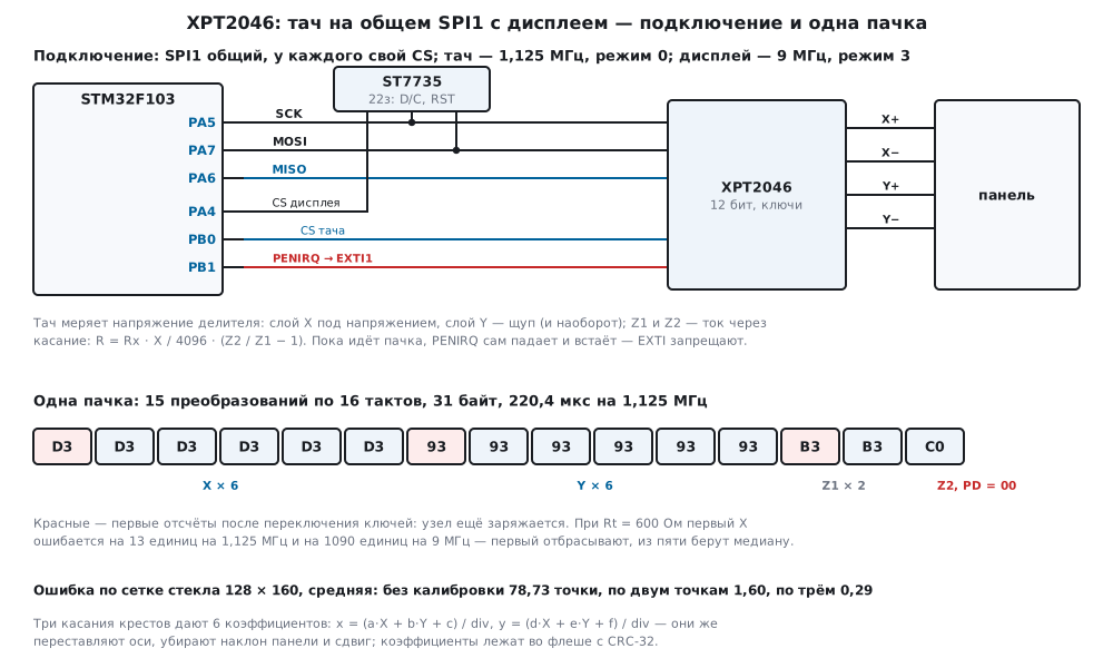
The touch has five signals: the clock DCLK, the data DIN and DOUT, the select CS and PENIRQ; the labels on module boards differ and were not checked here. The clock and data go onto the same SPI1 as the display from 22з; MISO, which the display did not need, is now needed by the touch.
| Touch | F103 | What |
|---|---|---|
| DCLK | PA5 | SPI1 clock, shared with the display |
| DIN | PA7 | MOSI, shared |
| DOUT | PA6 | MISO: input without pull |
| CS | PB0 | its own select: output, 1 at rest |
| PENIRQ | PB1 | PENIRQ: input with pull-up (1000, p. 160), EXTI1 on the falling edge |
| display CS | PA4 | held low in 22з — now it is driven |
PA5–PA7, PB0 and PB1 are not 5 V tolerant (DocID13587, p. 29): the touch
and the display run from 3.3 V. EXTI1 is tied to port B with the field
EXTI1[3:0] of AFIO_EXTICR1 = 0001 (p. 190).
Each has its own speed and mode. The display in 22з runs at 9 MHz
(72 MHz / 8) in mode 3. The touch needs a slow clock: the controller has
only a few clocks after the channel number to sample, and the node it
measures charges through the touch and the layer. The touch here runs at
72 MHz / 64 = 1.125 MHz (the manufacturer's documentation gives a limit of
about 2 MHz, not checked) in mode 0, as in Zephyr. The BR divider, CPOL
and CPHA are changed only between transfers (RM0008, p. 743–744): first
wait for the end of the display transfer — TXE, then BSY (p. 719) —
release its CS, switch SPI off, reconfigure:
static void bus_take(uint8_t who)
{
    spi_idle();
    if (owner == who)
        return;
    TFT_CS_HIGH();
    T_CS_HIGH();
    SPI1->CR1 = 0;
    SPI1->CR1 = who == BUS_TFT ? CR1_TFT : CR1_TOUCH;
    SPI1->CR1 |= SPI_CR1_SPE;
    wide = 0;
    owner = who;
    if (who == BUS_TFT)
        TFT_CS_LOW();                   /* дисплей держит CS, пока шину не попросит тач */
}
Every display bus function starts with bus_take(BUS_TFT), the touch port
with bus_take(BUS_TOUCH). The display CS goes low when the display takes
the bus and goes high only when the touch asks for it: the DMA of a pixel
row may still be running after the function returns (22з.1).
What the slow clock gives, the model showed with a still finger at the center. The switches change after the channel number, the sample is taken at the end of the command byte (a model assumption, four clocks); the node charges through Rt and half a layer onto 1 nF. Errors of the X samples in code units (one pixel of the glass is 23 units):
| SPI clock | Rt = 600 Ω: 1st / 2nd sample | median 2…6 | Rt = 3000 Ω: 1st / 2nd | median 2…6 |
|---|---|---|---|---|
| 562.5 kHz | 0 / 0 | 0 | −208 / 0 | 0 |
| 1.125 MHz | −13 / 0 | 0 | −653 / −7 | 0 |
| 2.25 MHz | −163 / 0 | 0 | −1159 / −117 | −1 |
| 4.5 MHz | −578 / −4 | 0 | −1544 / −491 | −50 |
| 9 MHz | −1090 / −86 | −1 | −1782 / −1005 | −319 |
| 18 MHz | −1498 / −421 | −33 | −1915 / −1437 | −810 |
The first sample after the switches change is always wrong — it is dropped. At 1.125 MHz the second one is already right even with a light press; at 9 MHz, the display speed, the median with Rt = 3000 Ω is off by 319 units — 14 pixels.
22к.3 X, Y and pressure: a burst of 16 clocks per conversion
The classic exchange is a command byte and two reply bytes, 24 clocks per conversion. The XPT2046 allows the next command to start while the low bits of the previous result are coming out: 16 clocks per conversion, as Zephyr does. One burst of the driver takes six X, six Y, two Z1 and one Z2 — 15 conversions:
int xpt_read(xpt_t *d, xpt_sample_t *s)
{
    uint8_t tx[XPT_FRAME_MAX] = {0}, rx[XPT_FRAME_MAX];
    uint16_t vx[XPT_NMAX], vy[XPT_NMAX], sx, sy;
    uint8_t n = d->n, m = 0, zr = d->skip ? 2u : 1u;
    uint32_t len;
    for (uint8_t i = 0; i < n; i++)
        tx[2u * m++] = XPT_X | XPT_PD_ON;
    for (uint8_t i = 0; i < n; i++)
        tx[2u * m++] = XPT_Y | XPT_PD_ON;
    for (uint8_t i = 0; i < zr; i++)
        tx[2u * m++] = XPT_Z1 | XPT_PD_ON;
    tx[2u * m++] = XPT_Z2 | d->pd_last;
    len = 2u * m + 1u;
    xpt_port_select(1);
    xpt_port_xfer(tx, rx, len);
    xpt_port_select(0);
    d->frames++;
    d->bytes += len;
    for (uint8_t i = 0; i < m; i++)                     /* бит 7 первого байта — BUSY, дальше 12 бит */
        s->raw[i] = (uint16_t)((rx[2u * i + 1u] & 0x7Fu) << 5 | rx[2u * i + 2u] >> 3);
    s->nraw = m;
    for (uint8_t i = 0; i < n; i++) {
        vx[i] = s->raw[i];
        vy[i] = s->raw[n + i];
    }
    s->x = xpt_median(vx + d->skip, (uint8_t)(n - d->skip), &sx);
    s->y = xpt_median(vy + d->skip, (uint8_t)(n - d->skip), &sy);
    s->spread = sx > sy ? sx : sy;
    s->z1 = s->raw[m - 2u];
    s->z2 = s->raw[m - 1u];
    /* R = Rx · X / 4096 · (Z2 / Z1 − 1) — сопротивление в точке касания: чем сильнее нажали, тем меньше */
    if (s->z1 == 0u)
        s->rt = XPT_NO_CONTACT;
    else if (s->z2 <= s->z1)
        s->rt = 0;
    else
        s->rt = (uint32_t)((uint64_t)d->rx_ohm * s->x * (uint32_t)(s->z2 - s->z1) / ((uint64_t)XPT_FULL * s->z1));
    s->ok = (uint8_t)(s->rt <= d->rt_max && s->spread <= d->spread_max);
    return s->ok;
}
A burst is 31 bytes, 220.4 µs at 1.125 MHz; with 24 clocks it would be 45 bytes and 320 µs. In the model all 15 codes decoded by the driver matched what the controller converted. The last command has PD = 00: after it the controller powers down and watches for a touch again; the others have PD = 11. Polling every 10 ms occupies the bus by 2.2 %.
Pressure. From the divider circuit (22к.1), Z1 and Z2 give the current through the touch, and the touch resistance is R = Rx · X / 4096 · (Z2 / Z1 − 1), where Rx is the resistance of layer X between X+ and X−: it is taken from the panel description or measured with an ohmmeter (400 Ω in the model). emWin also asks for the X layer resistance for pressure. The model at three points:
| Glass point | Rt = 300 Ω | 600 Ω | 1200 Ω | 3000 Ω |
|---|---|---|---|---|
| center (64, 80): driver R | 299 | 599 | 1201 | 2935 |
| center: Z1 + 4096 − Z2 | 2558 | 1860 | 1202 | 589 |
| corner (8, 8): Z1 + 4096 − Z2 | 3061 | 2443 | 1740 | 934 |
| corner (120, 152): Z1 + 4096 − Z2 | 1106 | 639 | 347 | 155 |
The formula returns Rt to within a few ohms at any point. The Zephyr measure Z1 + 4096 − Z2 (default threshold 100) is simpler, but at the same Rt = 600 Ω it differs 3.8 times between two corners: 2443 and 639. A threshold on it either misses light presses in one corner or accepts them in the other. The driver treats a touch as valid if R is at most 2000 Ω; with the panel released Z1 = 0, Z2 = 4095, and R is "no contact".
22к.4 Noise and bounce: drop the first, median, threshold, burst counting
A finger does not land on the panel at once: for the first milliseconds the contact breaks and closes again, a lightly pressed touch has a large Rt, and a broken layer floats and picks up interference. The same happens on release. The driver fights this on three levels: inside a burst — drop the first sample of each axis and take the median of the other five, if their spread is more than 24 units the burst is invalid; by pressure — R above 2000 Ω makes the burst invalid; between bursts — "down" only after two valid bursts in a row, "up" after three invalid ones.
uint16_t xpt_median(uint16_t *v, uint8_t n, uint16_t *spread)
{
    for (uint8_t i = 1; i < n; i++) {
        uint16_t t = v[i];
        uint8_t j = i;
        while (j > 0 && v[j - 1] > t) {
            v[j] = v[j - 1];
            j--;
        }
        v[j] = t;
    }
    *spread = (uint16_t)(v[n - 1] - v[0]);
    return v[n / 2];
}
The model touched the panel 150 times with a finger at random places, for 80…300 ms, with a bounce of 2…8 ms on press and 1…5 ms on release; polling every 10 ms and on PENIRQ. A point is wild if it is more than 4 glass pixels away from the finger:
| Method | Touches seen | Extra "down" | Wild points | Worst error | "Down" after the touch: mean / worst | "Up" after lifting |
|---|---|---|---|---|---|---|
| one sample, no thresholds | 150 | 74 | 202 of 2744 | 177.6 pixels | 0.0 / 0.0 ms | 16.8 ms |
| median of 5 out of 6 | 150 | 71 | 10 of 2742 | 174.4 pixels | 0.1 / 1.6 ms | 16.1 ms |
| + pressure and spread thresholds | 150 | 1 | 0 of 2704 | 1.5 pixels | 1.5 / 4.5 ms | 2.9 ms |
| + two and three bursts in a row | 150 | 0 | 0 of 2452 | 1.4 pixels | 18.3 / 20.0 ms | 22.8 ms |
The median removes noise inside a burst but not bounce: a burst taken at the moment of a break "floats" as a whole. Bounce is killed by the pressure threshold, and the last extra presses by burst counting. The price is about 18 ms to "down": two bursts of 10 ms.
22к.5 Three-point calibration
Panel codes are not screen pixels: the panel X axis may run along the
screen y, against it, at an angle, and the edges of the layer are wider
than the glass. All of this together is one affine transform:
x = (a·X + b·Y + c) / div and y = (d·X + e·Y + f) / div. Six unknowns
take three touches: the program draws a cross, waits for a touch and
takes the mean codes of the valid bursts of the press. The 3 × 3 system is
solved by Cramer's rule in integers — without the floating point the
Cortex-M3 does not have; c and f do not fit in 32 bits:
int cal_solve(cal_t *k, const int16_t sx[3], const int16_t sy[3], const uint16_t tx[3], const uint16_t ty[3])
{
    int64_t X0 = tx[0], X1 = tx[1], X2 = tx[2], Y0 = ty[0], Y1 = ty[1], Y2 = ty[2];
    int64_t div = (X0 - X2) * (Y1 - Y2) - (X1 - X2) * (Y0 - Y2);
    if (div == 0)
        return 0;
    k->div = (int32_t)div;
    k->a = (int32_t)((sx[0] - sx[2]) * (Y1 - Y2) - (sx[1] - sx[2]) * (Y0 - Y2));
    k->b = (int32_t)((X0 - X2) * (sx[1] - sx[2]) - (sx[0] - sx[2]) * (X1 - X2));
    k->c = Y0 * (X2 * sx[1] - X1 * sx[2]) + Y1 * (X0 * sx[2] - X2 * sx[0]) + Y2 * (X1 * sx[0] - X0 * sx[1]);
    k->d = (int32_t)((sy[0] - sy[2]) * (Y1 - Y2) - (sy[1] - sy[2]) * (Y0 - Y2));
    k->e = (int32_t)((X0 - X2) * (sy[1] - sy[2]) - (sy[0] - sy[2]) * (X1 - X2));
    k->f = Y0 * (X2 * sy[1] - X1 * sy[2]) + Y1 * (X0 * sy[2] - X2 * sy[0]) + Y2 * (X1 * sy[0] - X0 * sy[1]);
    return 1;
}
In the model the panel is glued with a 1.2° rotation, and its X axis runs along the glass y and against it. The crosses are at the points (13, 16), (115, 80) and (64, 144); each touch gave 37, 37 and 38 valid bursts. Then the model touched a grid of 15 × 19 = 285 points, from edge to edge of the glass:
| Conversion | Mean error | Worst | Middle: mean / worst | 10-pixel edge band: mean / worst |
|---|---|---|---|---|
| no calibration: X · 128 / 4096, Y · 160 / 4096 | 78.73 | 150.44 | 60.20 / 114.00 | 104.20 / 150.44 |
| two touches, axes swapped by hand | 1.60 | 4.59 | 1.22 / 3.82 | 2.11 / 4.59 |
| three touches | 0.29 | 2.00 | 0.10 / 1.00 | 0.56 / 2.00 |
Two points per axis — this is how the min/max limits in Zephyr and xPhys0/xPhys1 in emWin work — fix the scale, the offset and the direction of an axis, but not the rotation of the panel. Three points remove it too. What remains at the edges is the panel itself: near the edge the field of the layer is uneven (in the model the coordinate is compressed by up to 3 %), and a linear calibration cannot fix it. The integer conversion differed from floating point by no more than 0.5 pixel at all 285 points.
Storing in flash. The coefficients are 11 words, 44 bytes: the tag
0x4B32325A, a, b, d, e, c and f as two words each, div and the
CRC-32 of the first 40 bytes (the CRC-32 of the string "123456789" =
0xCBF43926 is the check value). The firmware writes them into the last
flash page in half-words, as in 11.5, and reads them at start-up: a valid
record gives 0; one flipped bit gives −2; an erased page (all 0xFFFFFFFF)
gives −1, and then calibration starts again. If the settings change
often, they go into the journal from 11.8.
Screen rotation. After tft_rotate from 22з the same codes must give
points in the new axes. cal_rotate recomputes the coefficients without
new touches. Without it the mean error with a 90° rotation is
84.36 pixels, with 180° — 116.47, with 270° — 84.55; with it in all three
— 0.29, worst 2.00.
22к.6 Gestures and PENIRQ: down, move, hold, up
While there is no touch, the bus is silent: the controller rests, PENIRQ is high. The first fall of PENIRQ wakes the main loop, then a burst runs every 10 ms until the touch ends. A step gives at most one event: "down" with a point, "move" when the point has gone more than 4 glass pixels away from where it was pressed, "hold" after 500 ms without moving, "up" with a "this was a tap" mark:
int tp_step(tp_t *t, int irq, uint32_t now_ms, tp_event_t *ev)
{
    ev->type = TP_NONE;
    ev->tap = 0;
    if (!t->active) {
        if (!irq)
            return TP_IDLE;
        t->active = 1;
        t->good = t->bad = 0;
        if (t->manage_irq)
            xpt_port_irq(0);                            /* пачки сами дёргают PENIRQ — не слушать его */
    }
    if (xpt_read(t->dev, &t->s)) {
        t->good = (uint8_t)(t->good < 255u ? t->good + 1u : 255u);
        t->bad = 0;
        cal_apply(&t->k, t->s.x, t->s.y, &t->x, &t->y);
    } else {
        t->bad = (uint8_t)(t->bad < 255u ? t->bad + 1u : 255u);
        t->good = 0;
    }
    if (!t->pressed) {
        if (t->good >= t->k_down) {
            t->pressed = 1;
            t->dragging = t->held = 0;
            t->x0 = t->x;
            t->y0 = t->y;
            t->t_down = now_ms;
            t->cx = t->cy = t->cn = 0;
            ev->type = TP_DOWN;
        } else if (t->bad >= t->k_up) {
            t->active = 0;                              /* касания нет: снова ждать PENIRQ */
            if (t->manage_irq)
                xpt_port_irq(1);
            return TP_IDLE;
        }
    } else if (t->good) {
        t->cx += t->s.x;
        t->cy += t->s.y;
        t->cn++;
        if (!t->dragging && (far(t->x, t->x0, t->slop) || far(t->y, t->y0, t->slop)))
            t->dragging = 1;
        if (t->dragging)
            ev->type = TP_MOVE;
        else if (!t->held && now_ms - t->t_down >= t->hold_ms) {
            t->held = 1;
            ev->type = TP_HOLD;
        }
    } else if (t->bad >= t->k_up) {
        t->pressed = 0;
        ev->type = TP_UP;
        ev->tap = (uint8_t)(!t->dragging && !t->held);
    }
    ev->x = t->x;
    ev->y = t->y;
    return TP_ACTIVE;
}
During a touch EXTI is disabled: every burst drives PENIRQ high by
itself and drops it at the end, when the controller returns to rest (in
the model; per the manufacturer's documentation, not checked). When
enabling EXTI again, the firmware first writes a one into EXTI_PR: the
bit is set by the selected edge and cleared by writing a one (RM0008,
p. 212), and the fall from the last burst may already have come.
In the model 20 taps of 100…250 ms, 10 holds of 0.8…1 s and 10 drags of 30…60 pixels were all recognized: 20 of 20, 10 of 10 and 10 of 10; the end of a drag is 0.8 pixel from the finger on average, the worst — 1.8. With a move threshold of 0 instead of 4, of 20 taps only 2 stayed taps, and of 10 holds — none: the jitter of the finger by one pixel is already a "drag".
How to treat PENIRQ, the model checked on 10 touches of 300 ms over 8.8 s:
| Firmware | "Down" | Bursts | Of them without a touch | Bus |
|---|---|---|---|---|
| EXTI disabled during a touch, PD = 00 at the end | 10 | 340 | 32 | 0.85 % |
| EXTI always enabled | 10 | 36 897 | 23 288 | 92.70 % |
| last command with PD = 11 | 1 | 34 | 4 | 0.09 % |
With EXTI enabled, every burst triggers the next one by its own end: 4205 bursts per second, and not only during a touch — in the model after a burst the floating layer X charges through the pull-up for tens of microseconds, and PENIRQ manages to fall. With PD = 11 on the last command the controller does not return to rest, PENIRQ is silent, and of 10 touches only one is seen — the first.
22к.7 Pitfalls
The touch at display speed lies on a light press. The bus was handed
to the touch, but BR was left from the display — 9 MHz. In the model
with Rt = 1800 Ω the error at three points is 8.6, 4.0 and 4.1 glass
pixels, at 1.125 MHz — 0.0, 1.0 and 0.0. A slow clock and a dropped first
sample (22к.2).
Garbage on the screen where nobody drew. The display CS, as in 22з, is held low, and the touch bytes go to the display as pixels (D/C = 1 from the previous picture). In the model 100 polling bursts left 1500 foreign pixels in the frame memory. The display CS is raised before the touch CS is lowered.
BR was changed in the middle of a DMA transfer. The last words of
the row go out at the touch speed. First the end of the transfer (TXE,
then BSY), then reconfiguration with SPE = 0 (RM0008, p. 743–744).
The bus is busy even when nobody touches the screen. EXTI was left
enabled, and PENIRQ itself wakes the next burst: 92.70 % of the bus in the
model. Disable EXTI during a touch and clear EXTI_PR before enabling.
After the first touch the touchscreen "died". The last command of the burst has PD = 11: the controller does not return to rest, PENIRQ does not work. The last command must have PD = 00, as in Zephyr.
One touch gives two or three "down" events, points fly to a corner. Contact bounce: without the pressure threshold there are 74 extra "down" events per 150 touches and points up to 177.6 pixels away from the finger (22к.4).
The axes are mixed up, after rotating the screen the finger "misses".
The names of channels X and Y are opposite in different drivers (Zephyr
and Clarinox), and panels are glued any way. Three-point calibration
swaps the axes by itself; after tft_rotate you need cal_rotate,
otherwise the mean error is 84…116 pixels.
Accuracy is worse at the edges. The field of the layer near the bus bars is uneven: after calibration the worst error in the middle is 1 pixel, at the edge — 2. Buttons at the very edge of the screen are made larger, calibration crosses are placed 10 % from the edges.
A capacitive screen is not read this way. A capacitive one has no divider of its own: a controller on the glass counts touches by itself and gives coordinates over I2C (22а.6). The XPT2046 and everything above is only for resistive panels.
22к.8 Summary
- A resistive panel is two divider layers: X is measured on Y+, Y on X+, the current through the touch is Z1 on X+ and Z2 on Y−; at rest a touch pulls PENIRQ down.
- The XPT2046 command byte: S, A2…A0, MODE, SER/DFR, PD1 PD0; X is 0xD0, Y is 0x90, Z1 is 0xB0, Z2 is 0xC0 (Zephyr channel numbers).
- A burst of 16 clocks per conversion: 15 conversions, 31 bytes, 220.4 µs at 1.125 MHz instead of 45 bytes and 320 µs; polling every 10 ms takes 2.2 % of the bus.
- SPI1 shared with the display: each has its own CS, 1.125 MHz and mode 0 for the touch versus 9 MHz and mode 3 for the display; the first sample after the switches is off by 13 units at 1.125 MHz and by 1090 at 9 MHz.
- Pressure: R = Rx · X / 4096 · (Z2 / Z1 − 1) — from 299 to 2935 Ω for the real 300…3000; the measure Z1 + 4096 − Z2 depends on the place by 3.8 times.
- Dropping the first, the median, thresholds of 2000 Ω and 24 units, two and three bursts in a row: 0 extra "down" and 0 wild points per 150 touches instead of 74 and 202.
- Three points: mean error 0.29 pixel, worst 2.00 (at the edge); two
points — 1.60 and 4.59; no calibration — 78.73. The coefficients are
44 bytes in flash with CRC-32; on screen rotation —
cal_rotate. - Gestures: tap, hold and drag — 20, 10 and 10 of 20, 10 and 10; EXTI disabled during a touch: 0.85 % of the bus instead of 92.70 %.
Full sources
xpt22k.h — the XPT2046 command byte, the driver, calibration and events: types and prototypes.
/* xpt22k.h — раздел 22к: резистивный тачскрин на контроллере XPT2046 без регистров микроконтроллера.
 * Драйвер говорит с XPT2046 через функции порта xpt_port_*: в прошивке fw22k.c их делает SPI1 STM32F103
 * (общий с дисплеем из 22з), в стенде host22k.c — строки к модели model22k.py.
 * Поля байта команды, номера каналов X, Y, Z1, Z2, «16 тактов на преобразование» и разбор 12-битного
 * результата — как в драйвере input_xpt2046.c из Zephyr 4.4.2; документа на XPT2046 в проекте нет. */
#ifndef XPT22K_H
#define XPT22K_H
#include <stdint.h>

/* ── байт команды: S A2 A1 A0 MODE SER/DFR PD1 PD0 ────────────────────── */
#define XPT_S          0x80u            /* старт: первая единица после CS = 0 */
#define XPT_A(ch)      ((uint8_t)(((ch) & 7u) << 4))
#define XPT_MODE8      0x08u            /* 1 — 8 бит, 0 — 12 бит */
#define XPT_SER        0x04u            /* 1 — однополярный вход, 0 — дифференциальный (здесь всегда 0) */
#define XPT_PD_ON      0x03u            /* PD = 11: между преобразованиями не выключаться */
#define XPT_PD_IRQ     0x00u            /* PD = 00: после преобразования выключиться — PENIRQ снова работает */
enum { XPT_CH_Y = 1, XPT_CH_Z1 = 3, XPT_CH_Z2 = 4, XPT_CH_X = 5 };    /* номера каналов — как в Zephyr */
#define XPT_X          (XPT_S | XPT_A(XPT_CH_X))       /* 0xD0 */
#define XPT_Y          (XPT_S | XPT_A(XPT_CH_Y))       /* 0x90 */
#define XPT_Z1         (XPT_S | XPT_A(XPT_CH_Z1))      /* 0xB0 */
#define XPT_Z2         (XPT_S | XPT_A(XPT_CH_Z2))      /* 0xC0 */

#define XPT_FULL       4096u            /* 12 бит */
#define XPT_NMAX       8u               /* отсчётов на ось в пачке — не больше */
#define XPT_CONV_MAX   (2u * XPT_NMAX + 3u)            /* X и Y по n, Z1 дважды, Z2 */
#define XPT_FRAME_MAX  (2u * XPT_CONV_MAX + 1u)        /* 16 тактов на преобразование + хвост */
#define XPT_NO_CONTACT 0xFFFFFFFFu

typedef struct {
    uint8_t n;                          /* отсчётов на ось за пачку, 1…8 */
    uint8_t skip;                       /* сколько первых отсчётов оси отбросить */
    uint8_t pd_last;                    /* PD у последней команды пачки: XPT_PD_IRQ */
    uint16_t spread_max;                /* разброс оставшихся отсчётов оси больше — пачка негодна */
    uint16_t rx_ohm;                    /* сопротивление слоя X между X+ и X− */
    uint32_t rt_max;                    /* сопротивление касания больше — нажатия нет */
    uint32_t frames, bytes;             /* пачек и байтов по SPI */
} xpt_t;

typedef struct {
    uint16_t x, y;                      /* медианы осей, 0…4095 */
    uint16_t z1, z2;
    uint16_t spread;                    /* наибольший разброс по осям X и Y */
    uint32_t rt;                        /* сопротивление касания, Ом; XPT_NO_CONTACT — контакта нет */
    uint8_t ok;                         /* 1 — касание годное: давление и разброс в пределах */
    uint8_t nraw;
    uint16_t raw[XPT_CONV_MAX];         /* все коды пачки по порядку — для стенда */
} xpt_sample_t;

/* ── порт: в прошивке — SPI1 и EXTI, в стенде — строки к модели ───────── */
void xpt_port_select(int on);           /* 1 — шину тачу (скорость, режим) и CS тача в 0; 0 — CS в 1 */
void xpt_port_xfer(const uint8_t *tx, uint8_t *rx, uint32_t n);    /* n байт туда и обратно */
void xpt_port_irq(int on);              /* EXTI линии PENIRQ: 1 — снять ожидание и разрешить, 0 — запретить */

/* ── драйвер ──────────────────────────────────────────────────────────── */
void xpt_init(xpt_t *d);                /* n = 6, skip = 1, пороги — по умолчанию */
int xpt_read(xpt_t *d, xpt_sample_t *s);                /* одна пачка: X, Y, Z1, Z2; 1 — касание годное */
uint16_t xpt_median(uint16_t *v, uint8_t n, uint16_t *spread);

/* ── калибровка по трём точкам: экран = аффинное преобразование кодов ── */
typedef struct {
    int32_t a, b, d, e;                 /* x = (a·X + b·Y + c) / div,  y = (d·X + e·Y + f) / div */
    int64_t c, f;
    int32_t div;
} cal_t;

int cal_solve(cal_t *k, const int16_t sx[3], const int16_t sy[3], const uint16_t tx[3], const uint16_t ty[3]);
void cal_apply(const cal_t *k, uint16_t tx, uint16_t ty, int16_t *x, int16_t *y);
void cal_rotate(const cal_t *portrait, uint8_t rot, uint16_t w, uint16_t h, cal_t *out);   /* как tft_rotate */

#define CAL_MAGIC      0x4B32325Au      /* «Z22K» */
#define CAL_WORDS      11u              /* запись во флеше: 44 байта */
uint32_t crc32(const void *p, uint32_t n);
void cal_pack(const cal_t *k, uint32_t rec[CAL_WORDS]);
int cal_unpack(const uint32_t rec[CAL_WORDS], cal_t *k);  /* 0 — запись годна */

/* ── события касания: нажал, ведёт, держит, отпустил ──────────────────── */
enum { TP_NONE = 0, TP_DOWN, TP_MOVE, TP_HOLD, TP_UP };
enum { TP_IDLE = 0, TP_ACTIVE = 1 };
#define TP_POLL_MS     10u              /* шаг опроса, пока касание идёт */

typedef struct {
    uint8_t type;
    uint8_t tap;                        /* у TP_UP: 1 — короткое касание без сдвига и удержания */
    int16_t x, y;
} tp_event_t;

typedef struct {
    xpt_t *dev;
    cal_t k;                            /* коды → точки экрана в текущем повороте */
    uint8_t k_down, k_up;               /* годных пачек подряд — «нажал», негодных — «отпустил» */
    uint8_t slop;                       /* сдвиг больше — уже перетаскивание, точек */
    uint8_t manage_irq;                 /* 1 — пока касание идёт, EXTI запрещено */
    uint16_t hold_ms;
    uint8_t active, pressed, good, bad, dragging, held;
    int16_t x0, y0, x, y;               /* где нажали и где сейчас */
    uint32_t t_down;
    uint32_t cx, cy, cn;                /* сумма кодов годных пачек нажатия — для калибровки */
    xpt_sample_t s;                     /* последняя пачка */
} tp_t;

void tp_init(tp_t *t, xpt_t *dev, const cal_t *k);
int tp_step(tp_t *t, int irq, uint32_t now_ms, tp_event_t *ev);    /* звать по PENIRQ и раз в TP_POLL_MS */

#endif
xpt22k.c — the XPT2046 driver, median and thresholds, three-point calibration, the flash record and gestures, shared by the firmware and the bench.
/* xpt22k.c — раздел 22к: драйвер XPT2046, фильтр, калибровка по трём точкам и события касания.
 * Один и тот же файл собирается в прошивку (armclang, Cortex-M3) и в стенд на компьютере (gcc):
 * микроконтроллера он не знает, только порт xpt_port_*. */
#include "xpt22k.h"

void xpt_init(xpt_t *d)
{
    d->n = 6;
    d->skip = 1;
    d->pd_last = XPT_PD_IRQ;
    d->spread_max = 24;
    d->rx_ohm = 400;
    d->rt_max = 2000;
    d->frames = d->bytes = 0;
}

/* Медиана: сортировка вставками (n ≤ 8), разброс — от наименьшего до наибольшего. */
uint16_t xpt_median(uint16_t *v, uint8_t n, uint16_t *spread)
{
    for (uint8_t i = 1; i < n; i++) {
        uint16_t t = v[i];
        uint8_t j = i;
        while (j > 0 && v[j - 1] > t) {
            v[j] = v[j - 1];
            j--;
        }
        v[j] = t;
    }
    *spread = (uint16_t)(v[n - 1] - v[0]);
    return v[n / 2];
}

/* Пачка в режиме 16 тактов на преобразование: команда i — в байте 2i, её 12 бит — в байтах 2i+1 и 2i+2,
 * следующая команда едет вместе с младшими битами предыдущего результата. Порядок: X × n, Y × n, Z1 (первый
 * отбрасывается при skip > 0), Z2; у последней команды PD = 00, чтобы PENIRQ снова работал. */
int xpt_read(xpt_t *d, xpt_sample_t *s)
{
    uint8_t tx[XPT_FRAME_MAX] = {0}, rx[XPT_FRAME_MAX];
    uint16_t vx[XPT_NMAX], vy[XPT_NMAX], sx, sy;
    uint8_t n = d->n, m = 0, zr = d->skip ? 2u : 1u;
    uint32_t len;
    for (uint8_t i = 0; i < n; i++)
        tx[2u * m++] = XPT_X | XPT_PD_ON;
    for (uint8_t i = 0; i < n; i++)
        tx[2u * m++] = XPT_Y | XPT_PD_ON;
    for (uint8_t i = 0; i < zr; i++)
        tx[2u * m++] = XPT_Z1 | XPT_PD_ON;
    tx[2u * m++] = XPT_Z2 | d->pd_last;
    len = 2u * m + 1u;
    xpt_port_select(1);
    xpt_port_xfer(tx, rx, len);
    xpt_port_select(0);
    d->frames++;
    d->bytes += len;
    for (uint8_t i = 0; i < m; i++)                     /* бит 7 первого байта — BUSY, дальше 12 бит */
        s->raw[i] = (uint16_t)((rx[2u * i + 1u] & 0x7Fu) << 5 | rx[2u * i + 2u] >> 3);
    s->nraw = m;
    for (uint8_t i = 0; i < n; i++) {
        vx[i] = s->raw[i];
        vy[i] = s->raw[n + i];
    }
    s->x = xpt_median(vx + d->skip, (uint8_t)(n - d->skip), &sx);
    s->y = xpt_median(vy + d->skip, (uint8_t)(n - d->skip), &sy);
    s->spread = sx > sy ? sx : sy;
    s->z1 = s->raw[m - 2u];
    s->z2 = s->raw[m - 1u];
    /* R = Rx · X / 4096 · (Z2 / Z1 − 1) — сопротивление в точке касания: чем сильнее нажали, тем меньше */
    if (s->z1 == 0u)
        s->rt = XPT_NO_CONTACT;
    else if (s->z2 <= s->z1)
        s->rt = 0;
    else
        s->rt = (uint32_t)((uint64_t)d->rx_ohm * s->x * (uint32_t)(s->z2 - s->z1) / ((uint64_t)XPT_FULL * s->z1));
    s->ok = (uint8_t)(s->rt <= d->rt_max && s->spread <= d->spread_max);
    return s->ok;
}

/* ── калибровка ───────────────────────────────────────────────────────── */
static int64_t rdiv(int64_t n, int64_t d)               /* деление с округлением к ближайшему */
{
    if (d < 0) {
        n = -n;
        d = -d;
    }
    return n >= 0 ? (n + d / 2) / d : -((-n + d / 2) / d);
}

/* Три точки экрана (sx, sy) и три пары кодов (tx, ty): x = (a·X + b·Y + c) / div — система 3 × 3 по Крамеру,
 * отдельно для x и для y. Возвращает 0, если точки на одной прямой. */
int cal_solve(cal_t *k, const int16_t sx[3], const int16_t sy[3], const uint16_t tx[3], const uint16_t ty[3])
{
    int64_t X0 = tx[0], X1 = tx[1], X2 = tx[2], Y0 = ty[0], Y1 = ty[1], Y2 = ty[2];
    int64_t div = (X0 - X2) * (Y1 - Y2) - (X1 - X2) * (Y0 - Y2);
    if (div == 0)
        return 0;
    k->div = (int32_t)div;
    k->a = (int32_t)((sx[0] - sx[2]) * (Y1 - Y2) - (sx[1] - sx[2]) * (Y0 - Y2));
    k->b = (int32_t)((X0 - X2) * (sx[1] - sx[2]) - (sx[0] - sx[2]) * (X1 - X2));
    k->c = Y0 * (X2 * sx[1] - X1 * sx[2]) + Y1 * (X0 * sx[2] - X2 * sx[0]) + Y2 * (X1 * sx[0] - X0 * sx[1]);
    k->d = (int32_t)((sy[0] - sy[2]) * (Y1 - Y2) - (sy[1] - sy[2]) * (Y0 - Y2));
    k->e = (int32_t)((X0 - X2) * (sy[1] - sy[2]) - (sy[0] - sy[2]) * (X1 - X2));
    k->f = Y0 * (X2 * sy[1] - X1 * sy[2]) + Y1 * (X0 * sy[2] - X2 * sy[0]) + Y2 * (X1 * sy[0] - X0 * sy[1]);
    return 1;
}

void cal_apply(const cal_t *k, uint16_t tx, uint16_t ty, int16_t *x, int16_t *y)
{
    *x = (int16_t)rdiv((int64_t)k->a * tx + (int64_t)k->b * ty + k->c, k->div);
    *y = (int16_t)rdiv((int64_t)k->d * tx + (int64_t)k->e * ty + k->f, k->div);
}

/* Калибровку снимают в книжной ориентации (w × h); для поворота rot — те же точки, что у tft_rotate:
 * 1 — x = gy, y = w−1−gx; 2 — x = w−1−gx, y = h−1−gy; 3 — x = h−1−gy, y = gx. Касаться заново не нужно. */
void cal_rotate(const cal_t *p, uint8_t rot, uint16_t w, uint16_t h, cal_t *o)
{
    int64_t W = (int64_t)(w - 1u) * p->div, H = (int64_t)(h - 1u) * p->div;
    *o = *p;
    switch (rot & 3u) {
    case 1:
        o->a = p->d, o->b = p->e, o->c = p->f;
        o->d = -p->a, o->e = -p->b, o->f = W - p->c;
        break;
    case 2:
        o->a = -p->a, o->b = -p->b, o->c = W - p->c;
        o->d = -p->d, o->e = -p->e, o->f = H - p->f;
        break;
    case 3:
        o->a = -p->d, o->b = -p->e, o->c = H - p->f;
        o->d = p->a, o->e = p->b, o->f = p->c;
        break;
    default:
        break;
    }
}

/* ── запись калибровки во флеш: 11 слов — метка, коэффициенты, CRC-32 ── */
uint32_t crc32(const void *p, uint32_t n)
{
    const uint8_t *b = p;
    uint32_t c = 0xFFFFFFFFu;
    while (n--) {
        c ^= *b++;
        for (int i = 0; i < 8; i++)
            c = c & 1u ? c >> 1 ^ 0xEDB88320u : c >> 1;
    }
    return ~c;
}

void cal_pack(const cal_t *k, uint32_t r[CAL_WORDS])
{
    r[0] = CAL_MAGIC;
    r[1] = (uint32_t)k->a;
    r[2] = (uint32_t)k->b;
    r[3] = (uint32_t)k->d;
    r[4] = (uint32_t)k->e;
    r[5] = (uint32_t)(uint64_t)k->c;
    r[6] = (uint32_t)((uint64_t)k->c >> 32);
    r[7] = (uint32_t)(uint64_t)k->f;
    r[8] = (uint32_t)((uint64_t)k->f >> 32);
    r[9] = (uint32_t)k->div;
    r[10] = crc32(r, 40);
}

int cal_unpack(const uint32_t r[CAL_WORDS], cal_t *k)
{
    if (r[0] != CAL_MAGIC)
        return -1;                                      /* стёртая страница: 0xFFFFFFFF */
    if (crc32(r, 40) != r[10])
        return -2;                                      /* запись побита или недописана */
    k->a = (int32_t)r[1];
    k->b = (int32_t)r[2];
    k->d = (int32_t)r[3];
    k->e = (int32_t)r[4];
    k->c = (int64_t)((uint64_t)r[6] << 32 | r[5]);
    k->f = (int64_t)((uint64_t)r[8] << 32 | r[7]);
    k->div = (int32_t)r[9];
    return k->div != 0 ? 0 : -3;
}

/* ── события ──────────────────────────────────────────────────────────── */
void tp_init(tp_t *t, xpt_t *dev, const cal_t *k)
{
    t->dev = dev;
    t->k = *k;
    t->k_down = 2;
    t->k_up = 3;
    t->slop = 4;
    t->hold_ms = 500;
    t->manage_irq = 1;
    t->active = t->pressed = t->good = t->bad = t->dragging = t->held = 0;
    t->x0 = t->y0 = t->x = t->y = 0;
    t->t_down = 0;
    t->cx = t->cy = t->cn = 0;
}

static int far(int16_t a, int16_t b, uint8_t slop)
{
    return a - b > slop || b - a > slop;
}

/* Шаг: пока касания нет, ждёт PENIRQ (irq = 1); дальше — пачка раз в TP_POLL_MS. «Нажал» — после k_down
 * годных пачек подряд, «отпустил» — после k_up негодных. На шаг — не больше одного события. */
int tp_step(tp_t *t, int irq, uint32_t now_ms, tp_event_t *ev)
{
    ev->type = TP_NONE;
    ev->tap = 0;
    if (!t->active) {
        if (!irq)
            return TP_IDLE;
        t->active = 1;
        t->good = t->bad = 0;
        if (t->manage_irq)
            xpt_port_irq(0);                            /* пачки сами дёргают PENIRQ — не слушать его */
    }
    if (xpt_read(t->dev, &t->s)) {
        t->good = (uint8_t)(t->good < 255u ? t->good + 1u : 255u);
        t->bad = 0;
        cal_apply(&t->k, t->s.x, t->s.y, &t->x, &t->y);
    } else {
        t->bad = (uint8_t)(t->bad < 255u ? t->bad + 1u : 255u);
        t->good = 0;
    }
    if (!t->pressed) {
        if (t->good >= t->k_down) {
            t->pressed = 1;
            t->dragging = t->held = 0;
            t->x0 = t->x;
            t->y0 = t->y;
            t->t_down = now_ms;
            t->cx = t->cy = t->cn = 0;
            ev->type = TP_DOWN;
        } else if (t->bad >= t->k_up) {
            t->active = 0;                              /* касания нет: снова ждать PENIRQ */
            if (t->manage_irq)
                xpt_port_irq(1);
            return TP_IDLE;
        }
    } else if (t->good) {
        t->cx += t->s.x;
        t->cy += t->s.y;
        t->cn++;
        if (!t->dragging && (far(t->x, t->x0, t->slop) || far(t->y, t->y0, t->slop)))
            t->dragging = 1;
        if (t->dragging)
            ev->type = TP_MOVE;
        else if (!t->held && now_ms - t->t_down >= t->hold_ms) {
            t->held = 1;
            ev->type = TP_HOLD;
        }
    } else if (t->bad >= t->k_up) {
        t->pressed = 0;
        ev->type = TP_UP;
        ev->tap = (uint8_t)(!t->dragging && !t->held);
    }
    ev->x = t->x;
    ev->y = t->y;
    return TP_ACTIVE;
}
fw22k.c — STM32F103 firmware: SPI1 for the display and the touch, PENIRQ on EXTI1, calibration in flash, finger drawing.
/* fw22k.c — раздел 22к: тачскрин на XPT2046 и дисплей ST7735 из 22з на одном SPI1 STM32F103 (BluePill), 72 МГц.
 * SPI1: SCK — PA5, MOSI — PA7, MISO — PA6 (нужен только тачу). Дисплей: CS — PA4, D/C — PA3, RST — PA2,
 * подсветка — PA1, 9 МГц, режим 3, пиксели через DMA1 канал 3 (как в 22з). Тач: CS — PB0, 1,125 МГц, режим 0;
 * PENIRQ → PB1: вход с подтяжкой, EXTI1 по спаду. Калибровка — последняя страница флеша 0x0800FC00.
 * Тактирование до 72 МГц — как в разделе 6; запись во флеш — как в 11.5. */
#include "stm32f10x.h"
#include "tft22i.h"
#include "xpt22k.h"

#define CR1_TFT   (SPI_CR1_MSTR | SPI_CR1_SSM | SPI_CR1_SSI | SPI_CR1_BR_1 | SPI_CR1_CPOL | SPI_CR1_CPHA)  /* /8, режим 3 */
#define CR1_TOUCH (SPI_CR1_MSTR | SPI_CR1_SSM | SPI_CR1_SSI | SPI_CR1_BR_2 | SPI_CR1_BR_0)                 /* /64, режим 0 */
#define TFT_CS_LOW()   (GPIOA->BSRR = 1u << (4 + 16))
#define TFT_CS_HIGH()  (GPIOA->BSRR = 1u << 4)
#define T_CS_LOW()     (GPIOB->BSRR = 1u << (0 + 16))
#define T_CS_HIGH()    (GPIOB->BSRR = 1u << 0)
#define DC_LOW()       (GPIOA->BSRR = 1u << (3 + 16))
#define DC_HIGH()      (GPIOA->BSRR = 1u << 3)
#define CAL_ADDR       0x0800FC00u      /* последняя страница 1 Кбайт у F103C8 */

enum { BUS_NONE, BUS_TFT, BUS_TOUCH };
static volatile uint32_t ticks;
static volatile uint8_t irq_flag;
static uint8_t owner = BUS_NONE, wide;
static uint16_t fill_word;

void SysTick_Handler(void)
{
    ticks++;
}

void EXTI1_IRQHandler(void)             /* PENIRQ: только флаг, пачка идёт в основном цикле */
{
    EXTI->PR = 1u << 1;
    irq_flag = 1;
}

static void delay_ms(uint32_t ms)
{
    uint32_t t0 = ticks;
    while (ticks - t0 < ms) {
    }
}

/* Конец передачи дисплея: DMA, потом TXE = 1 и BSY = 0 (RM0008, с. 719) — как spi_idle в 22з */
static void spi_idle(void)
{
    if (DMA1_Channel3->CCR & DMA_CCR1_EN) {
        while (!(DMA1->ISR & DMA_ISR_TCIF3)) {
        }
        DMA1->IFCR = DMA_IFCR_CTCIF3;
        DMA1_Channel3->CCR = 0;
    }
    while (!(SPI1->SR & SPI_SR_TXE)) {
    }
    while (SPI1->SR & SPI_SR_BSY) {
    }
    (void)SPI1->DR;
    (void)SPI1->SR;
}

/* Шину — тому, кто просит: дождаться конца прошлой передачи, снять CS прежнего хозяина и только при SPE = 0
 * сменить скорость и режим (BR, CPOL, CPHA не меняют во время обмена — RM0008, с. 743–744). */
static void bus_take(uint8_t who)
{
    spi_idle();
    if (owner == who)
        return;
    TFT_CS_HIGH();
    T_CS_HIGH();
    SPI1->CR1 = 0;
    SPI1->CR1 = who == BUS_TFT ? CR1_TFT : CR1_TOUCH;
    SPI1->CR1 |= SPI_CR1_SPE;
    wide = 0;
    owner = who;
    if (who == BUS_TFT)
        TFT_CS_LOW();                   /* дисплей держит CS, пока шину не попросит тач */
}

static void spi_width(uint8_t w16)
{
    if (wide == w16)
        return;
    SPI1->CR1 &= ~SPI_CR1_SPE;
    if (w16)
        SPI1->CR1 |= SPI_CR1_DFF;
    else
        SPI1->CR1 &= ~SPI_CR1_DFF;
    SPI1->CR1 |= SPI_CR1_SPE;
    wide = w16;
}

static void dma_go(const void *src, uint32_t n, uint32_t minc)
{
    DMA1_Channel3->CMAR = (uint32_t)src;
    DMA1_Channel3->CNDTR = n;
    DMA1_Channel3->CCR = DMA_CCR1_DIR | minc | DMA_CCR1_PSIZE_0 | DMA_CCR1_MSIZE_0 | DMA_CCR1_EN;
}

static void bus_reset(void)
{
    GPIOA->BSRR = 1u << (2 + 16);
    delay_ms(10);
    GPIOA->BSRR = 1u << 2;
    delay_ms(10);
}

static void bus_cmd(uint8_t c)
{
    bus_take(BUS_TFT);
    spi_width(0);
    DC_LOW();
    SPI1->DR = c;
}

static void bus_data(const uint8_t *p, uint32_t n)
{
    bus_take(BUS_TFT);
    spi_width(0);
    DC_HIGH();
    while (n--) {
        while (!(SPI1->SR & SPI_SR_TXE)) {
        }
        SPI1->DR = *p++;
    }
}

static void bus_pixels(const uint16_t *px, uint32_t n)
{
    bus_take(BUS_TFT);
    spi_width(1);
    DC_HIGH();
    dma_go(px, n, DMA_CCR1_MINC);
}

static void bus_fill(uint16_t c, uint32_t n)
{
    bus_take(BUS_TFT);
    spi_width(1);
    DC_HIGH();
    fill_word = c;
    while (n) {
        uint32_t k = n > 65535u ? 65535u : n;
        spi_idle();
        dma_go(&fill_word, k, 0);
        n -= k;
    }
}

static const tft_bus_t bus = {bus_reset, delay_ms, bus_cmd, bus_data, bus_pixels, bus_fill};

/* ── порт драйвера XPT2046 ────────────────────────────────────────────── */
void xpt_port_select(int on)
{
    if (on) {
        bus_take(BUS_TOUCH);            /* дисплей отпущен, SPI1 — 1,125 МГц, режим 0 */
        T_CS_LOW();
    } else {
        while (SPI1->SR & SPI_SR_BSY) {
        }
        T_CS_HIGH();
    }
}

void xpt_port_xfer(const uint8_t *tx, uint8_t *rx, uint32_t n)
{
    for (uint32_t i = 0; i < n; i++) {
        while (!(SPI1->SR & SPI_SR_TXE)) {
        }
        SPI1->DR = tx[i];
        while (!(SPI1->SR & SPI_SR_RXNE)) {
        }
        rx[i] = (uint8_t)SPI1->DR;
    }
}

void xpt_port_irq(int on)
{
    if (on) {
        EXTI->PR = 1u << 1;             /* спад от самой пачки уже мог взвести PR — снять до разрешения */
        irq_flag = 0;
        EXTI->IMR |= 1u << 1;
    } else {
        EXTI->IMR &= ~(1u << 1);
    }
}

/* ── калибровка во флеше: стереть страницу и записать 22 полуслова (раздел 11.5) ── */
static void flash_wait(void)
{
    while (FLASH->SR & FLASH_SR_BSY) {
    }
}

static int cal_save(const cal_t *k)
{
    uint32_t rec[CAL_WORDS];
    const uint16_t *h = (const uint16_t *)rec;
    int bad = 0;
    cal_pack(k, rec);
    FLASH->KEYR = 0x45670123u;
    FLASH->KEYR = 0xCDEF89ABu;
    flash_wait();
    FLASH->CR |= FLASH_CR_PER;
    FLASH->AR = CAL_ADDR;
    FLASH->CR |= FLASH_CR_STRT;
    flash_wait();
    FLASH->CR &= ~FLASH_CR_PER;
    FLASH->CR |= FLASH_CR_PG;
    for (uint32_t i = 0; i < 2u * CAL_WORDS; i++) {
        *(volatile uint16_t *)(CAL_ADDR + 2u * i) = h[i];
        flash_wait();
        bad |= (FLASH->SR & FLASH_SR_PGERR) != 0u;
    }
    FLASH->CR &= ~FLASH_CR_PG;
    FLASH->CR |= FLASH_CR_LOCK;
    return bad ? -1 : 0;
}

static tft_t tft;
static xpt_t xpt;
static tp_t tp;

/* Ждать касания и отпускания; вернуть средние коды годных пачек нажатия */
static void wait_tap(uint16_t *tx, uint16_t *ty)
{
    tp_event_t ev;
    uint32_t next = 0;
    for (;;) {
        int due = (int32_t)(ticks - next) >= 0;
        if (!irq_flag && !(tp.active && due)) {
            __WFI();
            continue;
        }
        if (!tp.active)
            next = ticks;
        next += TP_POLL_MS;
        int irq = irq_flag;
        irq_flag = 0;
        (void)tp_step(&tp, irq, ticks, &ev);
        if (ev.type == TP_UP && tp.cn) {
            *tx = (uint16_t)(tp.cx / tp.cn);
            *ty = (uint16_t)(tp.cy / tp.cn);
            return;
        }
    }
}

static void calibrate(cal_t *k)
{
    static const int16_t sx[3] = {13, 115, 64}, sy[3] = {16, 80, 144};
    uint16_t tx[3], ty[3];
    do {
        for (int i = 0; i < 3; i++) {
            tft_fill_rect(&tft, 0, 0, (int16_t)tft.w, (int16_t)tft.h, 0);
            tft_fill_rect(&tft, (int16_t)(sx[i] - 6), sy[i], 13, 1, 0xFFFFu);    /* крест */
            tft_fill_rect(&tft, sx[i], (int16_t)(sy[i] - 6), 1, 13, 0xFFFFu);
            wait_tap(&tx[i], &ty[i]);
        }
    } while (!cal_solve(k, sx, sy, tx, ty));
    (void)cal_save(k);
}

int main(void)
{
    cal_t k = {0, 0, 0, 0, 0, 0, 1};
    tp_event_t ev;
    uint32_t next = 0;
    int16_t px = 0, py = 0;
    RCC->APB2ENR |= RCC_APB2ENR_IOPAEN | RCC_APB2ENR_IOPBEN | RCC_APB2ENR_AFIOEN | RCC_APB2ENR_SPI1EN;
    RCC->AHBENR |= RCC_AHBENR_DMA1EN;
    GPIOA->BSRR = 1u << 2 | 1u << 3 | 1u << 4;         /* RST, D/C, CS дисплея — в 1 */
    GPIOA->CRL = (GPIOA->CRL & 0x0000000Fu)             /* PA0 не трогаем */
               | 0x2u << 4 | 0x3u << 8 | 0x3u << 12 | 0x3u << 16    /* PA1–PA4 — выходы */
               | 0xBu << 20 | 0x4u << 24 | 0xBu << 28;              /* PA5, PA7 — SPI1; PA6 — MISO, вход */
    GPIOB->BSRR = 1u << 0 | 1u << 1;                    /* CS тача в 1, подтяжка PENIRQ вверх */
    GPIOB->CRL = (GPIOB->CRL & ~0xFFu) | 0x82u;         /* PB0 — выход 2 МГц (0010), PB1 — вход с подтяжкой (1000) */
    SPI1->CR2 = SPI_CR2_TXDMAEN;
    DMA1_Channel3->CPAR = (uint32_t)&SPI1->DR;
    SysTick_Config(72000u);
    GPIOA->BSRR = 1u << 1;
    tft_init(&tft, &bus, 0, 1, 2, 1);                   /* дисплей из 22з */

    xpt_init(&xpt);
    xpt_sample_t s;
    (void)xpt_read(&xpt, &s);                           /* первая пачка кончается PD = 00 — PENIRQ включён */
    AFIO->EXTICR[0] = (AFIO->EXTICR[0] & ~0xF0u) | 0x10u;  /* EXTI1 ← PB1 */
    EXTI->FTSR |= 1u << 1;
    NVIC_EnableIRQ(EXTI1_IRQn);
    xpt_port_irq(1);
    tp_init(&tp, &xpt, &k);
    if (cal_unpack((const uint32_t *)CAL_ADDR, &k) != 0)
        calibrate(&k);
    tp.k = k;
    tft_fill_rect(&tft, 0, 0, (int16_t)tft.w, (int16_t)tft.h, 0);

    for (;;) {                                          /* рисование пальцем: точка, линия, удержание — стереть */
        int due = (int32_t)(ticks - next) >= 0;
        if (!irq_flag && !(tp.active && due)) {
            __WFI();
            continue;
        }
        if (!tp.active)
            next = ticks;
        next += TP_POLL_MS;
        int irq = irq_flag;
        irq_flag = 0;
        (void)tp_step(&tp, irq, ticks, &ev);
        if (ev.type == TP_DOWN)
            tft_fill_rect(&tft, (int16_t)(ev.x - 1), (int16_t)(ev.y - 1), 3, 3, 0xFFE0u);
        else if (ev.type == TP_MOVE)
            tft_line(&tft, px, py, ev.x, ev.y, 0x07FFu);
        else if (ev.type == TP_HOLD)
            tft_fill_rect(&tft, 0, 0, (int16_t)tft.w, (int16_t)tft.h, 0);
        px = ev.x;
        py = ev.y;
    }
}
Next: section 43 "Hardware cryptography: CRC, RNG, HASH, CRYP".