 Embedded HandbookApps
208. A device powered from 230 V mains: safety and power supply
For the whole book the device has lived on safe voltages: a bench supply, USB, a battery. The last step from prototype to product is the plug in the wall socket, and that step crosses a border: beyond it is a voltage that kills, and rules that were not written just to tick a box. This section is about thinking about the mains honestly: how much current will flow through a hand and why millimetres of clearance are circuit design too; what the input is built from — fuse, varistor, X capacitor; what crosses the isolation barrier and how to debug a board whose "ground" is rectified mains. The power input of the low-voltage side has already been covered (section 173), EMC is in 203; this section covers what appears only together with 230 V.
The numbers in this section are calculations from _verify/mains208/body_calc.py with
unit checking; the surge into the varistor and the X capacitor discharge are ngspice models
in the stm-lab:1 container (surge.cir, xcap.cir).
Terms used in the documentation
Term Meaning live / neutral the two current-carrying mains conductors protective earth (PE) the conductor that saves you when insulation fails to the enclosure SELV, safety extra-low voltage a voltage low enough to be safe to touch metal-oxide varistor (MOV) a zinc-oxide voltage clamp X / Y capacitor a capacitor across live and neutral / across the barrier bleeder resistor a resistor that discharges a capacitor time-lag / fast-acting fuse (T / F) a slow-blow / quick-blow fuse breaking capacity the highest current a fuse can safely interrupt isolation transformer a transformer whose output is not tied to earth differential probe a probe that measures between two points, neither of them ground
208.1 An honest look at the danger
What is dangerous is not the voltage itself but the current through the body, and Ohm's law
gives it. The body resistance, from contact to contact, at 230 V
is of the order of a kilohm: dry skin holds a few kilohms, but at
such a voltage its resistance drops quickly, and wet hands remove
the barrier at once. The calculation (body_calc.py):
| Contact | Resistance | Current |
|---|---|---|
| wet hands, firm grip | ~1 kΩ | 230 mA |
| dry skin, accidental touch | ~5 kΩ | 46 mA |
Compare with the thresholds: you feel it from 0.5–1 mA, at ~10 mA the forearm muscles contract on their own and you can no longer let go, and ~30 mA is taken as the danger threshold for fibrillation. The worst case — 230 mA — is 7.7 times above the fibrillation threshold, and "dry skin" only saves you until the first drop of sweat. This gives three practical consequences.
The one-hand rule. The most dangerous current path is hand to hand, through the chest and the heart. You work on live equipment with one hand; the other does not hold the enclosure, the bench or an earthed instrument. This rule is older than the transistor, and it still works.
An RCD at the workbench. A residual current device compares the current in live and neutral and breaks the circuit when they differ by ~30 mA within tens of milliseconds — before fibrillation starts. The workshop socket where mains devices are opened must go through an RCD: it is cheap insurance against exactly the scenario calculated above.
An isolation transformer on the bench. Its secondary is not tied to earth, so touching one wire does not close a circuit through the floor: only the current through the winding capacitance to earth flows — with a typical 100 pF that is 7.2 µA, below the threshold of sensation. But between the two secondary wires there are still 230 V, and an RCD behind an isolation transformer does not work — it has nothing to compare. Isolation removes one scenario, not the danger.
⚠️ Switched off does not mean discharged. The reservoir capacitor after the bridge (the "bulk cap") is charged to the peak mains value: 230 V · √2 = 325 V. Pulling the plug does not discharge it: measure first, then touch. Discharge it with a resistor of a few kilohms, not a screwdriver — a spark of hundreds of amperes damages the capacitor, the screwdriver and your hearing.
208.2 Architecture: whoever owns the barrier is responsible
The first decision for a mains device is who holds the barrier between 230 V and your low-voltage circuit. There are three options:
| Option | Barrier | What is left to you |
|---|---|---|
| external adapter | inside the adapter | only the low-voltage part: no mains in the enclosure |
| ready-made board-mount AC/DC module | inside the module | the input per the module datasheet: fuse, varistor, clearances around the primary pins |
| your own switching supply (section 58) | all yours | everything: transformer, clearances, protection, tests |
For a small batch the choice is almost always one of the first two rows, and here is why. A mains converter is not "a somewhat harder circuit": it is insulation that has to be proven by tests (section 206), an EMC filter that has to be debugged (section 203), a transformer that for small batches is wound to order, and a layout where every millimetre is subject to inspection (208.3). A module has already been through all of this: its datasheet declares reinforced insulation, the test voltage and the application category. A module costs more than discrete parts, but only volume can pay back the cost of your own development and testing — at tens or hundreds of units, saving on the module is a net loss.
An external adapter is even more radical: there is no mains in the enclosure at all, the whole device lives on safety extra-low voltage, and for it section 208 ends with choosing the adapter. If the design allows it, this is the best option for a first version: the device is certified as low-voltage, and the mains part is the responsibility of someone else's, already certified, unit.
🔧 A module does not replace the external parts. The datasheet of an AC/DC module lists the external components: fuse, varistor, sometimes a filter. They are not "recommended" — without a fuse a failed module heats up from the socket all the way to a fire. And the clearances around the module's primary pins on your board are yours: it is not the module's fault that a trace runs a millimetre away from its mains pin.
208.3 Clearance and creepage: millimetres as circuit design
Insulation on a board is measured by two distances (section 54.5): clearance is
the shortest path through air, creepage is the shortest path along
the board surface. Why these are different numbers and why both are measured
in millimetres follows from two calculations (body_calc.py).
Dry air in a uniform field breaks down at roughly 3 kV/mm — a peak of 325 V is held by a layer of 0.11 mm. If clearance were sized "for 230 V", a coat of lacquer would be enough. But clearance is sized for the worst day: a lightning surge in a socket outlet network is a few kilovolts (2.5 kV is a typical value for plug-in equipment), the field at sharp trace corners is far from uniform, the air can be humid, and the factory can be imprecise. 2.5 kV gives 0.83 mm in the ideal case; a margin of several times for edges, humidity and spread turns this into the typical ~3 mm for basic insulation and ~6 mm for reinforced.
The path along the surface is longer: a surface is weaker than air. Dust absorbs moisture, current flows through the film, and the current burns conductive carbon tracks into the laminate — so breakdown does not come instantly but after months of operation. The speed of this process depends on the material and contamination, so the creepage for 230 V mains is ~4 mm basic, ~8 mm reinforced (the same numbers as in 54.5).
For the board layout this means:
- between primary and secondary there is a strip with no copper on any layer, including inner layers and ground pours: the barrier exists through the thickness of the board, not only on top;
- packages that sit on the barrier (optocoupler, transformer) are checked by their own pins: the "primary pin to secondary pin" distance along the surface must reach the same millimetres, and a trace under the package reduces it to zero (54.5);
- where the millimetres are not enough, use a milled slot: creepage goes around it along its walls, and a slot a millimetre or more wide lengthens the path by twice its depth; a slot does not increase the air clearance;
- the barrier boundary is drawn on the silkscreen: the assembler and the repairer can see where the low-voltage zone ends.
⚠️ Flux is contamination too. Unwashed flux in the barrier zone absorbs moisture and conducts: creepage calculated for clean laminate is shorter across flux. The barrier zone is washed and inspected by eye — this is cheaper than a single return from repair.
208.4 The isolation barrier: what crosses it
The barrier divides the device into two countries: the primary lives on the mains, the secondary on safety extra-low voltage. The border can be crossed by exactly three things, and each one has a special construction:
- the converter's transformer: energy crosses through the magnetic field; the insulation between windings is reinforced: either two independent layers, each of which holds the working voltage on its own, or one with a double margin — the failure of one layer must not connect the two sides;
- the feedback optocoupler (section 54): the signal crosses as light; the optocoupler package is part of the barrier, and its "pin to pin" pair across the package must hold the same millimetres (208.3);
- the Y capacitor: the only element that connects the sides with a galvanically significant capacitance — and therefore the most critical one.
A Y capacitor is needed because the barrier is not transparent to noise: the transformer winding capacitance is tens of picofarads, and the common-mode current from the converter switching leaks through it into the secondary and further into the cables (54.5, 203.2). A Y capacitor between primary and secondary ground returns this current home by a short path — without it the product radiates noise through its cables.
The price is leakage current through the capacitor itself: 2.2 nF at 50 Hz
pass 159 µA from the mains (body_calc.py). This is below the threshold of sensation,
but already comparable with it — so the Y capacitance is not increased "to be safe":
its ceiling is set by the permissible current through a person who touches
the secondary or the enclosure.
⚠️ Class Y only. A failed Y capacitor puts the mains on the secondary. Class Y capacitors are built to fail open rather than short, and they withstand kilovolt pulses; subclass Y1 is used across reinforced insulation, Y2 across basic insulation. An ordinary "3 kV" ceramic capacitor is not a class: when it fails, it fails short. The same goes for the X capacitor: class X self-heals after breakdown, which is why it is placed across the mains.
208.5 The input: fuse, varistor, X capacitor
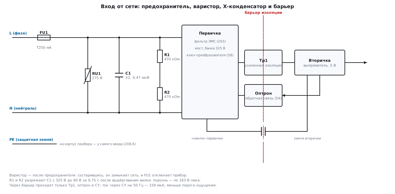
The fuse is the first element after the plug, and it is chosen not "for
230 V" but by current. An estimate for a 10 W device: a switching supply input with a bridge
and a bulk cap draws current in sharp peaks, the power factor is ~0.6, efficiency
~0.85 — an RMS input current of 85 mA (body_calc.py). The rating is taken
with a margin of two to three times over the operating current — T250 mA: the letter T means
time-lag, because at switch-on the bulk cap charges with a surge
(the inrush current with a 10 Ω NTC thermistor reaches 32.5 A in the first
half-cycle; a fast-acting fuse will not survive that). The voltage
on the fuse body — "250 V" — is not the working voltage
but the arc-quenching condition: a 32 V fuse in a mains circuit will blow
— and keep conducting through an arc. The breaking
capacity points the same way: the short-circuit current at a socket is hundreds of amperes,
and the fuse body must be able to interrupt it without flying apart.
The varistor meets what the fuse is useless against: a surge
lasts microseconds, a fuse element heats up in milliseconds. A zinc-oxide
disc opens sharply above its threshold and absorbs the surge
energy itself. The ngspice model (surge.cir): a 2 kV surge with an internal
resistance of 2 Ω into a 275 V AC varistor gives a peak current of 664 A,
the voltage across the circuit is held at 672 V, the peak power is 446 kW,
and the absorbed energy is ~15 J over about a hundred microseconds. Compare with the
static discharge from 203.3 — 4.8 mJ: the surge carries three thousand times more energy, so
a varistor is a centimetre-sized disc, not a bead, and so behind the
varistor you still need a smaller clamp on the inputs (173, 62).
A varistor ages: every surge it absorbs moves its threshold down,
an aged varistor leaks, heats up and in the end shorts the mains. That is why
it sits after the fuse: the last act of its life is a blown
FU1 and a de-energized device, not a fire.
The X capacitor is a class X film capacitor across the mains, the differential-mode part
of the EMC filter (203, 168). It has one non-obvious duty: to discharge
before a person reaches the pins of the unplugged plug. The worst
case is that the plug is pulled at the peak of the sine wave, leaving
325 V on the capacitor. A bleeder resistor is placed in parallel: 0.47 µF with a pair
of series 470 kΩ resistors (940 kΩ in total) discharges
to a safe 60 V in 0.75 s — ngspice (xcap.cir) and the RC calculation
t = RC·ln(325/60) agree. Without the resistor the film holds its charge
for hours. Two resistors instead of one because of voltage: the peak is split
in half, 163 V per package, which fits the limit of the 1206
size (small packages have a maximum working voltage of tens of volts, 166.6).
The price is 56 mW of continuous heating, 0.49 kWh per year: for a device
that aims at low standby consumption this is a noticeable line in the budget,
and there the discharge is done by a circuit — but that is optimization, not safety.
🔧 Order at the input. From the plug: fuse → varistor → X capacitor with bleeder → common-mode choke → bridge. The fuse comes before everything, so that it protects the protection too; the varistor right after it, so that the surge does not reach the filter; X after the varistor, so that the film does not take the surge.
208.6 Two grounds and the enclosure
A mains device has two grounds, and they must not be confused. Protective earth PE is the third conductor of the socket: it takes no part in the operation of the circuit, its only task is to keep the enclosure safe. A fault from live to a metal enclosure without PE turns the enclosure into an electrode at 230 V; with PE it becomes a short circuit that trips the breaker. Hence the construction: PE connects to the enclosure right at the entry point, short and with a bolt and washer, not through a chain of painted panels; in appliance connectors the PE contact is made longer than the others — when unplugged, it breaks last.
The signal ground of the secondary is the ordinary minus of your circuit. It meets the enclosure the way described in 203.4: at one point, at the connectors, so that a discharge into the enclosure goes to PE bypassing the board. If the device is class I (with PE), the EMC setup is complemented by a Y capacitor from the secondary ground to the enclosure — a path for common-mode noise that does not tie the grounds together at 50 Hz. A class II device does without PE altogether: there the barrier is double insulation, the enclosure is more often plastic, and all leakage current to a person is limited by the barrier Y capacitor (208.4).
The only thing forbidden to both grounds is chance meetings: a mounting standoff touching the secondary pour, a scratch in the solder mask under a screw. Every such meeting is either a bypass of the barrier or a ground loop (54.1).
208.7 Debugging under mains
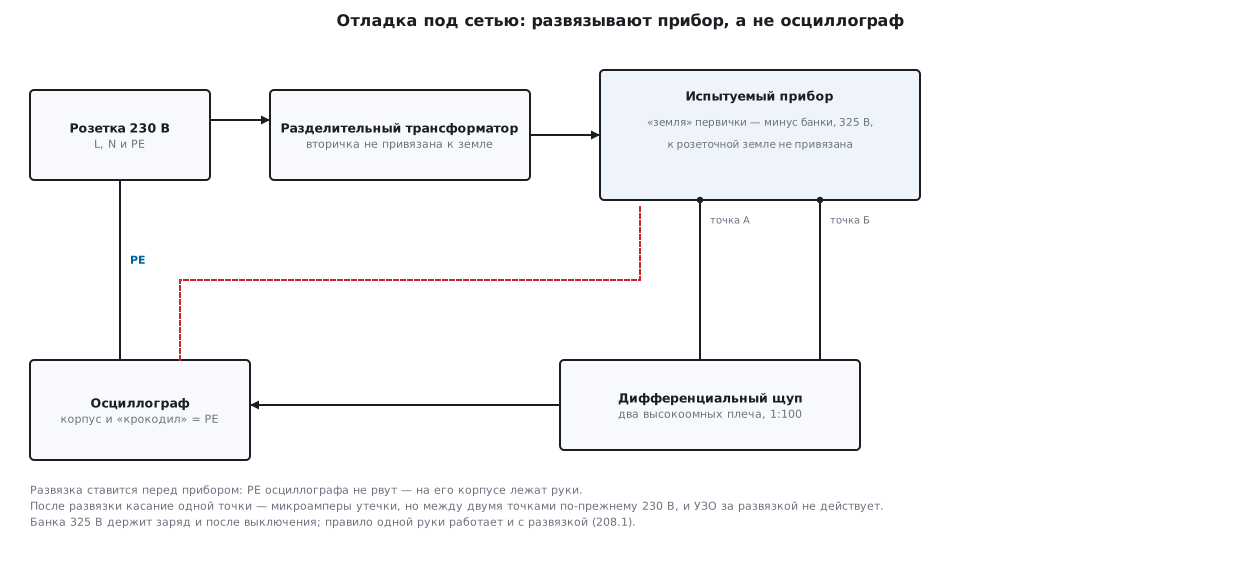
The main debugging trap is described in 36а.5: the probe's ground clip is connected
to the oscilloscope chassis, and the chassis to the socket PE. But the "ground" of the primary —
the minus of the bulk cap — is not ground at all: through a conducting bridge diode it connects
to live every time live is below neutral. A ground clip on the bulk cap minus
is a short circuit from live to PE on every second half-cycle:
the current is limited only by the wiring — of the order of 460 A until the breaker
in the panel trips (body_calc.py), and the first things to burn are the clip lead, the board
trace or the oscilloscope input.
The correct bench is set up like this:
- isolate the device, not the oscilloscope: the isolation transformer feeds the device under test, the oscilloscope PE stays intact — your hands rest on its chassis. After isolation the primary is not tied to earth anywhere, touching one point with the ground clip is no longer a short circuit — but 208.1 still applies: between two points of the primary there are still 230 V, and an RCD behind the isolation does not work;
- probe the primary with a differential probe: two high-impedance arms, 1:100 division, it measures between two points, neither of which has to be ground. This is the only proper way to look at the switch gate or the current shunt under mains;
- debug the low-voltage part without mains: the secondary with the barrier removed is an ordinary 5 V board, you power it from a bench supply (36а.8) and debug it for a month, and connect the mains for the week of final testing. The fewer hours the board spends under mains, the fewer chances statistics has;
- a debugger only on an isolated board: SWD connects the board ground to the computer; for a board connected to the mains this is the same ground clip (54.6). A mains-powered device in the field is debugged over isolated channels — optocoupler, isolated UART, radio.
🔧 The power-up ritual. With the cover of a mains device off: an RCD in the socket, isolation on the bench, one hand, measure the bulk cap before touching, after switching off — measure again. The five points take thirty seconds and cover all the scenarios from 208.1.
208.8 Pitfalls
A click, a burnt trace and a dead oscilloscope input. The probe's ground clip touched the "minus" of the primary: through a bridge diode the bulk cap minus sits on live every second half-cycle, a short to PE is hundreds of amperes (208.7). Into the primary — only with a differential probe or after isolating the device.
The device behind the isolation transformer is "safe", and a person holds both terminals. Isolation removes the path through the floor, but between the secondary wires there are the full 230 V, and an RCD behind the transformer will not trip. The one-hand rule applies with isolation too (208.1).
The fuse blows on every second switch-on. A fast-acting (F) rating calculated from the average current is fitted: the inrush charging of the bulk cap is tens of amperes in the first half-cycle (with a 10 Ω NTC, 32.5 A). Fit a time-lag (T) one with a two- to threefold margin: T250 mA for a 10 W device (208.5).
After half a year in the field the device is charred around the varistor. The varistor ages with every surge: the threshold creeps down, leakage grows, the disc heats up. The varistor goes after the fuse — its final short circuit must end in a blown fuse element, not a smouldering board (208.5).
A shock from the pins of the unplugged plug. An X capacitor without a bleeder resistor holds the peak 325 V for hours. A 940 kΩ bleeder brings it to 60 V in 0.75 s; the resistor is made of two in series, 163 V peak per package (208.5, 166.6).
The insulation passed on the bench — breakdown at the customer half a year later. The creepage has been eaten: unwashed flux, dust and moisture conduct along the surface, tracking burns a path into the laminate over weeks. Wash the barrier zone, keep the millimetres from 208.3 and do not forget the inner layers.
A class II device tingles. The leakage current through the barrier Y capacitor reaches the threshold of sensation: the Y capacitance was chosen "bigger for EMC". The ceiling for Y is the current through a person: 2.2 nF give 159 µA from the mains; do not increase it, look for the common-mode problem in the filter and layout instead (203).
208.9 Summary
- Current through the body is Ohm's law: 230 V across ~1 kΩ of wet hands is 230 mA, 7.7 times above the ~30 mA fibrillation threshold; "can't let go" starts at ~10 mA. One hand, a 30 mA RCD in the workshop, a 325 V bulk cap — measure, then touch.
- An isolation transformer makes touching one point safe (leakage ~7.2 µA through 100 pF), but between two points there are still 230 V, and an RCD behind it does not work.
- A small batch buys the barrier ready-made: an external adapter or an AC/DC module with the datasheet's external parts; your own switching supply means insulation, EMC and tests (58, 203, 206), which only volume pays for.
- Distances for 230 V: through air ~3 mm basic / ~6 mm reinforced — sized for kilovolt surges, not for 325 V (0.11 mm holds those); along the surface ~4 mm / ~8 mm — the surface ages; a copper-free strip on all layers, a slot lengthens the path by twice its depth.
- Three things cross the barrier: a transformer with reinforced insulation, an optocoupler and a class Y capacitor (it fails open); 2.2 nF means 159 µA of leakage, the ceiling is set by a person, not by EMC.
- Input: a time-lag fuse chosen by current (85 mA calculated → T250 mA, inrush with a 10 Ω NTC is 32.5 A), a varistor after it (a 2 kV/2 Ω surge: 664 A, 672 V, ~15 J — three thousand times more than a static discharge), an X capacitor with a 940 kΩ bleeder — 60 V in 0.75 s at the cost of 56 mW.
- PE goes to the enclosure at the entry and through a long contact; the signal ground meets the enclosure at one point at the connectors (203.4); debugging means isolating the device, a differential probe, the low-voltage part without mains, SWD only on an isolated board.
Next: section 208а "A device powered from 24 V: industrial supply, input protection and digital inputs" — from the mains to the 24 V bus in the cabinet: surges from neighbouring coils, input protection, digital inputs and outputs.