 Embedded HandbookApps
208б. A 230 V load from a microcontroller: relay, triac, solid-state relay
Section 208 brought the mains into the device and set up the isolation barrier, 208а built a device powered from industrial 24 V. One last step remains: a 3.3 V microcontroller pin has to switch on a heater, a lamp or a motor at 230 V. There are three ways — a relay, a triac via an opto-triac, and a solid-state relay — and each has its own physics: a coil that does not want to release, a triac that turns off only at zero current, a zero-crossing detector that is off by a millisecond. All of this is calculated here, and at the end a timer catches the mains zero crossing itself and fires the triac at the required angle.
Foundations: the flyback diode — 51.2, relays and solid-state relays in general terms —
52.6, the optocoupler and its current transfer ratio — 54.2 and 54.3, clearances and the barrier —
208.3 and 208.4, timer input capture and one-pulse mode — 13.6 and 13.8,
the input filter — 13.10, the RMS value — 57.2, interference — 203. The numbers
in this section come from the PC model _verify/load208b/load208b.py (run —
load208b_host.txt), the code is load208b.c, built with armclang for the F103 and
G474.
Terms used in the documentation
Term Meaning triac a bidirectional thyristor opto-triac, random-phase / zero-crossing an opto-triac without / with a zero-crossing detector solid-state relay (SSR) a relay with no moving contacts, built on a triac latching current / holding current the current needed to latch the triac on / to keep it on snubber an RC circuit across the switch zero-crossing detector a circuit that marks the mains passing through zero phase-angle control switching on at an angle within each half-cycle burst-fire, integral-cycle control switching whole mains cycles on and off Trigger Mode trigger mode: the counter starts on an input edge One pulse mode one-pulse mode PWM mode 2 PWM mode 2: the output is active while CNT ≥ CCR fSAMPLING=fDTS/32, N=8 the longest input filter: 8 samples at fDTS/32
208б.1 Relay: the coil releases later than it seems
The coil circuit is already in 52.6: a transistor switch and a flyback diode in parallel with the winding (51.2). The diode saves the switch, but it has a price: slow release. After the switch turns off, the coil current does not vanish but decays with the L/R law, and while it is large the armature holds.
Model: the coil from 51.2: 12 V, 30 mA, about 100 mH. Resistance
400 Ω, time constant L/R = 0.25 ms, stored energy 45 µJ. The current decays
to zero in t = (L/R) · ln(1 + I·R/Uclamp), where Uclamp is the clamp
voltage; numerical integration gave the same numbers:
| Clamp | Current decay | On the switch | Absorbed by the clamp |
|---|---|---|---|
| diode | 0.62 ms | 13.1 V | 6 µJ of 45 |
| diode + 24 V Zener | 0.098 ms | 37.1 V | 34 µJ of 45 |
| diode + 47 V Zener | 0.056 ms | 60.1 V | 39 µJ of 45 |
A 24 V Zener in series with the diode speeds up the decay 6.3 times. A TVS clamp plays the same role (173). The price is the voltage on the switch: 37.1 V instead of 13.1 V, and the transistor is chosen with a margin over that number. With a diode alone the energy goes into the winding resistance, with a Zener into the Zener. This is the current decay, not the armature release time: the mechanics add their own, and the model does not calculate them — you look at the contact with an oscilloscope.
Why speed matters. The contacts separate under current, and an arc strikes between them. On AC it goes out by itself at the next current zero, that is no later than 10 ms, but every arc burns away contact metal. Slow release means a longer path through the arc zone.
Lifetime is calculated by division (52.6): 100000 cycles. A thermostat clicking once every 60 s uses it up in 69.4 days. Burst control with a period of 1 s (208б.5) uses it up in 27.8 hours, that is in 1.2 days. Conclusion: a relay is for infrequent switching; frequent switching needs a triac.
A relay cannot switch on at zero. The relay operate time is about 10 ms (52.6), and it drifts. If you issue the command from the zero detector, corrected for the average time, the contact closes not at zero but with a spread:
| Operate time spread | Angle from zero | Voltage on the contact at closing |
|---|---|---|
| ±0.5 ms | ±9° | up to 51 V |
| ±1 ms | ±18° | up to 101 V |
| ±2 ms | ±36° | up to 191 V |
Without synchronization — up to the peak 325 V. The gain is real only if the spread of the specific relay was measured, not made up; the spread in the model is a parameter, not a datasheet value.
208б.2 RC snubber: the calculation
Across a contact or a triac a series R and C circuit is placed — a snubber. It does two things: it suppresses the spark at the contact and limits the rate of rise of voltage on the triac after turn-off. Too fast a rise turns the triac on again, without a gate pulse. Example: 100 Ω and 100 nF.
A closed switch leaks. At 50 Hz, 100 nF has a reactance of 31.8 kΩ, and 7.23 mA flows through the snubber even with the load switched off. For a heater this is nothing, but a small load — an LED lamp, the coil of a mains relay — may glow or fail to release from this current. The resistor dissipates only 5.2 mW. The capacitor is in series with the load across the mains, so it must be class X (208.4).
The resistor cannot be removed. When switched on at the peak of the sine wave, the charged capacitor discharges straight into the switch; 100 Ω limit the peak to 3.25 A.
An inductive load is the worst case. Example: 230 V, 0.5 A, power factor 0.6. That is |Z| = 460 Ω: 276 Ω resistive and 1.171 H, the current lags by 53.1°. The triac turns off at zero current, and the mains voltage at that moment is 260 V, and it lands on the closed switch as a step. The model (Runge–Kutta method, load plus snubber):
| Snubber | Peak on the switch | Highest rate | Damping |
|---|---|---|---|
| 100 Ω + 100 nF | 534 V | 0.75 V/µs | 0.05 |
| 470 Ω + 100 nF | 498 V | 0.70 V/µs | 0.11 |
| 1000 Ω + 100 nF | 459 V | 0.65 V/µs | 0.19 |
| 100 Ω + 22 nF | 529 V | 1.61 V/µs | 0.03 |
Two conclusions. A smaller capacitance means a faster rise: 22 nF give 1.61 V/µs against 0.75. And the snubber together with the load inductance is a resonant circuit: the voltage on the switch overshoots the 325 V peak to 534 V, and a larger resistor damps the oscillation more and lowers the peak to 459 V. The permissible rate of rise and the voltage class are taken from the triac datasheet; there is no datasheet on disk, so here there is only a comparison of variants. The model has no core losses in the load, the real peak is lower, but the voltage margin is designed for the modelled one.
208б.3 Triac, opto-triac, solid-state relay
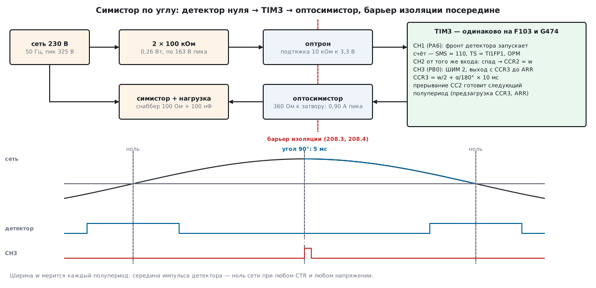
A triac is turned on by a gate current pulse and then holds itself on until the load current falls below the holding current — that is, until the next current zero. So on AC it turns off by itself every half-cycle, and on DC it will never turn off (52.6). The second condition is the latching current: while the gate pulse lasts, the load current must manage to reach it, otherwise the triac turns off after the pulse. The values of both currents come from the datasheet of the specific device; it is not on disk, so they are not here. Hence the pulse length in the listing — 200 µs. If you fire at zero itself, by the end of the pulse the mains rises to only 20.4 V: a 2000 W heater (26.45 Ω) reaches 0.77 A. A low-power load may not reach the latching current — then the pulse is lengthened or the triac is fired slightly after zero.
An opto-triac carries the command across the barrier: an LED on the microcontroller side, a small triac on the mains side. Its triac feeds current into the gate of the power triac through a resistor. The resistor limits the surge: with 360 Ω and firing at the peak, 0.90 A peak, and the opto-triac must withstand this surge according to its datasheet. Opto-triacs come in two kinds:
- without a zero-crossing detector — turns on at any moment while the LED is lit; only these are used for phase control (208б.5);
- with a zero-crossing detector — turns on only while the mains voltage is close to zero; you cannot do phase control with it, only whole half-cycles. The line in 54.6 "zero-crossing opto-triac" is about switching on and off, not about regulation.
Heating. The drop across a conducting triac is described by a threshold V0 and
a resistance r: P = V0 · Iavg + r · Irms², where Iavg is the average absolute
current and Irms the RMS current. The example parameters are V0 = 1 V, r = 20 mΩ;
this is not a datasheet but an order of magnitude for the calculation:
| Mode | Irms | Iavg | Loss |
|---|---|---|---|
| 2000 W heater, fully on | 8.70 A | 7.83 A | 9.34 W |
| the same, 90° angle | 6.15 A | 3.91 A | 4.67 W |
The peak current is 12.30 A. The simplified estimate "1 V × current" gives 8.70 W — close, but lower. The loss is 0.47 % of the load power: little for the load, a lot for the package. The heatsink is calculated from the temperature rise: with the junction no higher than 125 °C and air at 50 °C (also example parameters), at 9.34 W only 8.03 K/W is allowed. Subtract junction-to-case 1.5 K/W and case-to-heatsink 0.5 K/W (example) — and 6.03 K/W is left for the heatsink. This is no longer a patch of copper on the board but a real heatsink. And check in the datasheet whether the package tab is connected to a terminal: if it is, the heatsink is at mains potential, and the clearances of 208.3 apply to it.
A solid-state relay is an opto-triac and a power triac in one package, with or without a zero-crossing detector. Which one to take is decided by the load. Model:
| Load | Switching on at voltage zero | Switching on at the peak |
|---|---|---|
| 1 µF capacitance through 10 Ω | peak current 0.102 A | peak current 32.5 A |
| inductance without saturation | peak flux 2.00 of nominal | peak flux 1.00 |
For a heater and a capacitance — a zero-crossing relay: no current step, less interference. For a transformer and a motor it is the opposite: switching on at voltage zero doubles the flux in the core, the core saturates and draws an inrush current. They are switched on at the peak — a relay without a zero detector with the command timed from the detector of 208б.4. Only a relay without a zero detector is suitable for phase control.
208б.4 Zero-crossing detector
The classic detector is an optocoupler with anti-parallel LEDs (54.2), connected to the mains through two 100 kΩ resistors. The output has a 10 kΩ pull-up to 3.3 V. Away from zero the LED current is large, the transistor is on, the output is zero; near zero the current is small, the transistor turns off, the output is one. The result is a pulse around every mains zero crossing.
The resistors. Together they dissipate 0.262 W, 0.131 W each, and each holds 163 V peak — the same two-package logic as for the X capacitor bleeder (208.5). The peak LED current is 1.62 mA.
Where the edge is. The output crosses half the supply when the phototransistor current can no longer hold the pull-up. This threshold depends on the current transfer ratio, and it varies from 50 to 600 % and halves with ageing (54.2). The model for three values — 25 % (the 50 % minimum halved), 100 % and 600 %:
| Ratio | Mains threshold | Edge before zero | Pulse width |
|---|---|---|---|
| 25 % | 133.2 V | 1.343 ms = 24.2° | 2.69 ms |
| 100 % | 34.2 V | 0.335 ms = 6.0° | 0.67 ms |
| 600 % | 6.7 V | 0.066 ms = 1.2° | 0.13 ms |
The edge is a poor zero: between units it drifts by 1.3 ms. But the pulse is symmetrical about zero, and the middle of the pulse is the mains zero at any ratio. That is what is used: measure the width w, the zero is w/2 after the edge. The mains voltage also moves the edge: at a 100 % ratio and mains at −10 % the edge moves earlier by 0.037 ms (+0.67°), at +10 % later by 0.031 ms (−0.55°); the middle stays in place.
The cost of a microsecond at 50 Hz is 0.018°. The timer input filter (13.10)
in its longest variant — 8 samples at fDTS/32 with CKD = ÷4 —
delays every edge by 14.2 µs on the F103 (72 MHz) and by 6.0 µs
on the G474 (170 MHz). Both edges are delayed equally, the middle does not
shift. What the model does not know is the different turn-on and turn-off times
of the optocoupler itself (54.3): with a large pull-up the fall and rise are asymmetric,
and the middle drifts. This is measured with an oscilloscope on the finished board.
The input is timer capture, not EXTI. Capture takes the timestamp in hardware (13.6), and interrupt latency does not affect it. EXTI also works, but then everything that delays the interrupt ends up in the angle.
A resistive detector without isolation — 1 MΩ straight to the pin, and the pin's protection diode limits the voltage. The peak current into the diode is 0.325 mA, the 1.65 V threshold is crossed 16.1 µs after zero — 0.29°. Accurate and cheap, but only if the whole board itself lives on the mains without isolation, with all the consequences of 208.7: no debugger. And the pin must allow injected current. On the F103, PA6 is an ordinary pin, the datasheet allows ±5 mA. On the G474, PA6 is a TT_a pin, and for such pins the datasheet states that positive injected current is not possible (−5/0 mA): an external diode is needed there.
208б.5 Phase and burst control
Phase. The triac is fired with a delay t after zero; the angle is α = t / 10 ms · 180°. For a resistive load the power is the mean of the squared voltage over the conducting part of the half-cycle:
P(α) / Pmax = 1 − α/π + sin(2α) / (2π)
The model checked the formula against numerical integration at every point:
| Angle | Delay from zero | P / Pmax | RMS voltage |
|---|---|---|---|
| 0° | 0 µs | 1.0000 | 230.0 V |
| 30° | 1667 µs | 0.9712 | 226.7 V |
| 45° | 2500 µs | 0.9092 | 219.3 V |
| 60° | 3333 µs | 0.8045 | 206.3 V |
| 90° | 5000 µs | 0.5000 | 162.6 V |
| 120° | 6667 µs | 0.1955 | 101.7 V |
| 135° | 7500 µs | 0.0908 | 69.3 V |
| 150° | 8333 µs | 0.0288 | 39.1 V |
| 170° | 9444 µs | 0.0011 | 7.7 V |
| 180° | 10000 µs | 0 | 0 V |
The relationship is non-linear: the first 30° barely reduce the power, the last 30° give almost nothing. So the firmware holds an inverse table — a delay for each power step; the model solved the equation by bisection:
| Power | 10 % | 20 % | 30 % | 40 % | 50 % | 60 % | 70 % | 80 % | 90 % |
|---|---|---|---|---|---|---|---|---|---|
| angle | 133.4° | 119.5° | 108.6° | 99.1° | 90.0° | 80.9° | 71.4° | 60.5° | 46.6° |
| delay, µs | 7411 | 6637 | 6036 | 5504 | 5000 | 4496 | 3964 | 3363 | 2589 |
The price of phase control is harmonics. At 90° the load current is a chopped sine wave: the first harmonic is 0.593 of the full amplitude, the third 0.318 (54 % of the first), the fifth 0.106 (18 %). Every firing is also a current step with a steep edge. This is interference into the mains and over the air (203), so heaters are not regulated by phase; phase is needed where bursts do not work — the brightness of incandescent lamps, the speed of a brushed motor.
Two angle errors. If you take the detector edge as zero instead of the middle, at a 25 % ratio the intended 90° become 65.8°, and the power comes out as 0.753 instead of 0.500. If the mains frequency is 1 % low (49.5 Hz), the 5000 µs delay calculated for 50 Hz gives 89.1° and a power of 0.5100 instead of 0.5000 — this is tolerable, but for accuracy the half-period is measured between neighbouring zeros.
Bursts. The triac is fired at zero for whole periods, and the power is set by the fraction of periods switched on. Whole periods, not half-periods: if you switch on every other half-period, they will all have the same polarity, and the load gets a DC component of 103.5 V (Upeak/π), which the mains and transformers do not like. With whole periods it is 0 V.
The power step is set by the window: 50 periods (1 s) give 2 %, 100 periods (2 s) 1 %. How to spread the on-periods within the window is a question of ripple. As a block ("the first N of 50") — long pauses; with an accumulator (add the level to a sum and switch a period on when it overflows past 100) — evenly:
| Level | Accumulator: on out of 100 | Longest pause | Block in a window of 50: pause |
|---|---|---|---|
| 10 % | 10 | 9 periods, 180 ms | 45 periods, 900 ms |
| 30 % | 30 | 3 periods, 60 ms | 35 periods, 700 ms |
| 50 % | 50 | 1 period, 20 ms | 25 periods, 500 ms |
| 90 % | 90 | 1 period, 20 ms | 5 periods, 100 ms |
A heater does not care about ripple — it has thermal inertia; a lamp
on bursts flickers. The accumulator in the listing is the next_delay_us function.
208б.6 Code: TIM3 catches the zero and fires the triac by itself
The idea is to keep the processor out of the timing. The detector input is PA6, TIM3 channel 1; the output to the opto-triac LED is PB0, channel 3. On the F103 these are their default functions, on the G474 both use alternate function AF2. The tick is 1 µs: TIM3 gets 72 MHz on the F103 (APB1 at 36 MHz, and when the APB1 prescaler is not 1 the timer is clocked at twice the rate) and 170 MHz on the G474 (APB1 without a prescaler).
- Trigger mode (
SMS= 110,TS= TI1FP1): the rising edge of the detector pulse starts the counter by itself; one-pulse mode (OPM) stops it on the update event. - Channel 2 from the same input, on the falling edge (
CC2S= 10,CC2P):CCR2receives the pulse width w — the mains zero was w/2 after the start. - Channel 3 in PWM mode 2: the output is active while
CNT≥CCR3, and goes off at the update, when the count reachesARR. The pulse to the opto-triac runs fromCCR3= w/2 + delay toARR. - The falling-edge interrupt prepares the next half-cycle: it writes
CCR3andARR. Both are preloaded (OC3PE,ARPE) and take effect at the next trigger. A late interrupt does not shift the angle: the timer generates the pulse.
The delay is limited from above by the margin to the next edge: the pulse must
end before it. With the widest width of 2700 µs (25 % ratio)
the largest delay is 8350 µs, that is 150.3° and a P/Pmax of 0.0280; phase control cannot go lower
than that, and 10 % with its 7411 µs fits. This is what
_Static_assert checks together with the register masks — the compiler will not build the code
if the numbers disagree.
void triac_init(void)
{
#if defined(STM32F10X_MD)
    RCC->APB2ENR |= RCC_APB2ENR_IOPAEN | RCC_APB2ENR_IOPBEN;
    RCC->APB1ENR |= RCC_APB1ENR_TIM3EN;
    GPIOA->CRL = (GPIOA->CRL & ~(0xFu << 24)) | (0x4u << 24);   /* PA6: вход без подтяжки */
    GPIOB->CRL = (GPIOB->CRL & ~0xFu) | 0xAu;                    /* PB0: альтернативная функция, 2 МГц */
#else
    RCC->AHB2ENR |= RCC_AHB2ENR_GPIOAEN | RCC_AHB2ENR_GPIOBEN;
    RCC->APB1ENR1 |= RCC_APB1ENR1_TIM3EN;
    GPIOA->MODER = (GPIOA->MODER & ~(3u << 12)) | (2u << 12);    /* PA6: AF2 — TIM3_CH1 */
    GPIOA->AFR[0] = (GPIOA->AFR[0] & ~(0xFu << 24)) | (2u << 24);
    GPIOB->MODER = (GPIOB->MODER & ~3u) | 2u;                    /* PB0: AF2 — TIM3_CH3 */
    GPIOB->AFR[0] = (GPIOB->AFR[0] & ~0xFu) | 2u;
#endif
    TIM3->PSC = TIM_CLK_HZ / TICK_HZ - 1u;
    TIM3->CR1 = TIM_CR1_CKD_1 | TIM_CR1_ARPE | TIM_CR1_OPM;     /* tDTS = 4 такта; стоп на обновлении */
    TIM3->CCMR1 = TIM_CCMR1_CC1S_0 | TIM_CCMR1_IC1F             /* IC1 ← TI1, фильтр fDTS/32, N = 8 */
                | TIM_CCMR1_CC2S_1;                             /* IC2 ← тот же TI1 */
    TIM3->CCMR2 = TIM_CCMR2_OC3M_2 | TIM_CCMR2_OC3M_1 | TIM_CCMR2_OC3M_0 | TIM_CCMR2_OC3PE;
    TIM3->CCER = TIM_CCER_CC2E | TIM_CCER_CC2P | TIM_CCER_CC3E;  /* IC2 — по спаду */
    TIM3->SMCR = TIM_SMCR_TS_2 | TIM_SMCR_TS_0 | TIM_SMCR_SMS_2 | TIM_SMCR_SMS_1;
    TIM3->ARR = W_MAX_US + GUARD_US;
    TIM3->CCR3 = 0xFFFFu;                       /* до первого измерения ширины — не открывать */
    TIM3->EGR = TIM_EGR_UG;                     /* теневые ARR и CCR3 ← предзагрузка */
    TIM3->SR = 0u;
    TIM3->DIER = TIM_DIER_CC2IE;
    NVIC_EnableIRQ(TIM3_IRQn);
}
Until the width has been measured, CCR3 = 0xFFFF is greater than ARR, and the output never
turns on — the triac stays off from the first half-cycle. The handler:
/* спад импульса детектора: CCR2 — его ширина w, ноль был через w/2 после фронта */
void TIM3_IRQHandler(void)
{
    uint32_t w, d, d_max, start, stop;

    if (!(TIM3->SR & TIM_SR_CC2IF))
        return;
    w = TIM3->CCR2;                             /* чтение снимает флаг */
    d = next_delay_us();
    if (d >= HALF_US || w > W_MAX_US) {         /* пропустить: сравнение за пределом ARR */
        TIM3->ARR = W_MAX_US + GUARD_US;
        TIM3->CCR3 = 0xFFFFu;
        return;
    }
    d_max = HALF_US - w / 2u - PULSE_US - GUARD_US;
    if (d > d_max)
        d = d_max;                              /* импульс кончается до следующего фронта */
    start = w / 2u + d + 1u;                    /* CCR3 > 0: иначе импульса не будет */
    stop = start + PULSE_US;
    if (stop < w + GUARD_US)
        stop = w + GUARD_US;                    /* счёт идёт, пока не пойман спад */
    TIM3->CCR3 = start;                         /* обе записи вступят на следующем запуске */
    TIM3->ARR = stop;
}
In phase mode next_delay_us takes the delay from the table in 208б.5
(k_delay_us in the file — the same 11 numbers from 10000 to 0), in burst mode it uses the
accumulator: the first half-cycle of a pair decides for both, so only
whole periods are switched on. The width w is taken from the current half-cycle, while the angle
is applied in the next one — the width changes slowly, so this is a fair trade.
The code was built with armclang for the F103 and G474 with -Wall -Wextra without warnings:
the TIM3 register and bit names are the same on both, only the
port setup differs.
208б.7 Pitfalls
The relay releases late, the contacts turn black. A flyback diode alone stretches the coil current decay to 0.62 ms, the contacts separate slowly, the arc lasts longer. A 24 V Zener in series with the diode speeds up the decay 6.3 times, but raises the voltage on the switch to 37.1 V (208б.1).
A relay in burst control died over the weekend. A lifetime of 100000 cycles at a period of 1 s is 27.8 hours. Bursts — only with a triac (208б.1).
A switched-off lamp glows. A 100 Ω + 100 nF snubber passes 7.23 mA with the switch closed; that is enough for a small load to glow. Reduce the capacitance, keeping in mind that 22 nF raise the rate of rise to 1.61 V/µs (208б.2).
With an inductive load the triac turns on by itself after zero. The current lags the voltage, and at zero current 260 V lands on the switch as a step. Without a snubber the rate of rise is limited only by the triac's own capacitance. A snubber limits the rate, but with the load it rings up to 534 V — choose a triac with a voltage margin (208б.2).
Two identical boards deliver different power. The detector edge was taken as zero, and it drifts with the optocoupler ratio: at 25 % it is 1.343 ms before zero, 90° turn into 65.8°, the power is 0.753 instead of 0.500. Zero is the middle of the detector pulse (208б.4).
Phase control does not work: the load is either fully on or off. An opto-triac or solid-state relay with a zero detector turns on only near zero: a command at 90° will be executed at the next zero. For phase control use devices without a zero detector (208б.3).
A transformer switched by a "zero-crossing" relay trips the breaker. Switching on at voltage zero doubles the flux in the core (2.00 of nominal against 1.00 at the peak), and the core saturates. For a transformer, switch on at the peak (208б.3).
Half-period bursts make the transformer hum. Every other half-period has the same polarity, a DC component of 103.5 V. Switch on whole periods (208б.5).
On the G474 a resistive detector damages the input. PA6 on the G474 is a TT_a pin, positive injected current is not possible on it according to the datasheet. Use an external diode to the supply or an optocoupler detector; on the F103 PA6 allows ±5 mA (208б.4).
The triac behaves strangely during a Flash erase. A page erase
takes 20…40 ms on the F103 and 22.02…24.47 ms on the G474 according to the datasheets — 2…4
half-cycles. Reading the same Flash bank during an erase stalls the
bus (as RM0440 states), and an interrupt handler located in that bank waits.
Meanwhile the timer keeps producing pulses from the last CCR3 and ARR: phase control holds the previous angle, while bursts freeze
in the last decision — on or off. Erase while the load is
off, or move the handler to RAM.
The triac heatsink gave an electric shock. In many packages the tab is connected to a terminal, and the heatsink ends up at mains potential. Check the datasheet, fit an insulating pad or keep the clearances of 208.3 (208б.3).
208б.8 Summary
- A 12 V, 30 mA, 100 mH relay coil: with a diode the current decays in 0.62 ms, with a diode and a 24 V Zener in 0.098 ms (6.3 times faster), at the cost of 37.1 V on the switch. A lifetime of 100000 cycles: once every 60 s — 69.4 days, once a second — 1.2 days.
- Switching a relay on at zero depends on the operate time spread: ±1 ms means ±18° and up to 101 V on the contact instead of 325 V.
- A 100 Ω + 100 nF snubber: 7.23 mA of leakage through the closed switch, 3.25 A of discharge when switched on at the peak; on an inductive load of 0.5 A with a power factor of 0.6 — 0.75 V/µs and ringing up to 534 V, 1 kΩ lowers the peak to 459 V.
- A triac stays on until zero current; the latching and holding currents come from the datasheet. An opto-triac without a zero detector is for phase control, with a detector only for bursts. Losses at 2000 W with V0 = 1 V, r = 20 mΩ are 9.34 W, leaving 6.03 K/W for the heatsink.
- A zero-crossing solid-state relay is for heaters and capacitances (0.102 A against 32.5 A), one without it is for transformers (flux 1.00 against 2.00) and phase control.
- An optocoupler detector: the edge moves away from zero by 0.066…1.343 ms depending on the current transfer ratio, the middle of the pulse is exactly zero; 1 µs = 0.018°, the 14.2 / 6.0 µs input filter on both edges does not move the middle.
- Phase:
P/Pmax = 1 − α/π + sin(2α)/(2π); 50 % is 90° and 5000 µs, 10 % is 133.4° and 7411 µs; at 90° the third harmonic is 54 % of the first. - Bursts use whole periods (every other half-period gives 103.5 V of DC component); a window of 50 periods gives a 2 % step, the accumulator keeps the pause at 50 % to 1 period instead of 25 for a block.
- TIM3 in trigger mode with one-pulse mode: the detector edge starts the count, channel 2 measures the width, channel 3 in PWM mode 2 outputs a 200 µs pulse; the timer sets the angle, the interrupt only prepares the next half-cycle. The same on the F103 and G474.
Full sources
load208b.c — phase-angle triac control: TIM3 catches the zero detector and outputs the pulse by itself.
/* 208б: симистор по углу — TIM3 ловит импульс детектора нуля и сам выдаёт
   импульс на оптосимистор в одноимпульсном режиме.
   PA6 — TIM3_CH1, вход от детектора; PB0 — TIM3_CH3, выход на светодиод оптосимистора.
   Собирается armclang: -DSTM32F10X_MD (stm32f10x.h) или -DSTM32G474xx (stm32g4xx.h). */
#include <stdint.h>

#if defined(STM32F10X_MD)
#define TIM_CLK_HZ 72000000u            /* APB1 36 МГц, таймер получает ×2 */
#else
#define TIM_CLK_HZ 170000000u
#endif
#define TICK_HZ    1000000u             /* тик 1 мкс */
#define HALF_US    10000u               /* полупериод сети 50 Гц */
#define PULSE_US   200u                 /* импульс на светодиод оптосимистора */
#define GUARD_US   100u                 /* запас до следующего фронта детектора */
#define W_MAX_US   2700u                /* самый широкий импульс детектора (CTR 25 %) */
#define D10_US     7411u                /* задержка для 10 % мощности */
#define MODE_PHASE 0u
#define MODE_BURST 1u

static const uint16_t k_delay_us[11] = {        /* мощность 0, 10 … 100 % → задержка от нуля */
    HALF_US, D10_US, 6637, 6036, 5504, 5000, 4496, 3964, 3363, 2589, 0};

_Static_assert(TIM_CLK_HZ % TICK_HZ == 0u && TIM_CLK_HZ / TICK_HZ - 1u <= 0xFFFFu, "PSC: целое, 16 бит");
_Static_assert(sizeof k_delay_us / sizeof k_delay_us[0] == 11u, "ступени 0…100 % через 10");
_Static_assert(W_MAX_US + 2u * GUARD_US < HALF_US, "спад детектора ловится до следующего фронта");
_Static_assert(HALF_US - W_MAX_US / 2u - PULSE_US - GUARD_US >= D10_US, "10 % помещается при самом широком импульсе");
_Static_assert((TIM_SMCR_TS_2 | TIM_SMCR_TS_0 | TIM_SMCR_SMS_2 | TIM_SMCR_SMS_1) == 0x56u, "TS=101 TI1FP1, SMS=110 запуск");
_Static_assert((TIM_CCMR2_OC3M_2 | TIM_CCMR2_OC3M_1 | TIM_CCMR2_OC3M_0 | TIM_CCMR2_OC3PE) == 0x78u, "CH3: ШИМ 2, предзагрузка");
_Static_assert((TIM_CCMR1_CC1S_0 | TIM_CCMR1_IC1F | TIM_CCMR1_CC2S_1) == 0x2F1u, "IC1 и IC2 от TI1, фильтр 1111");

static volatile uint8_t g_mode, g_level;        /* режим и мощность 0…100 % */

void triac_init(void)
{
#if defined(STM32F10X_MD)
    RCC->APB2ENR |= RCC_APB2ENR_IOPAEN | RCC_APB2ENR_IOPBEN;
    RCC->APB1ENR |= RCC_APB1ENR_TIM3EN;
    GPIOA->CRL = (GPIOA->CRL & ~(0xFu << 24)) | (0x4u << 24);   /* PA6: вход без подтяжки */
    GPIOB->CRL = (GPIOB->CRL & ~0xFu) | 0xAu;                    /* PB0: альтернативная функция, 2 МГц */
#else
    RCC->AHB2ENR |= RCC_AHB2ENR_GPIOAEN | RCC_AHB2ENR_GPIOBEN;
    RCC->APB1ENR1 |= RCC_APB1ENR1_TIM3EN;
    GPIOA->MODER = (GPIOA->MODER & ~(3u << 12)) | (2u << 12);    /* PA6: AF2 — TIM3_CH1 */
    GPIOA->AFR[0] = (GPIOA->AFR[0] & ~(0xFu << 24)) | (2u << 24);
    GPIOB->MODER = (GPIOB->MODER & ~3u) | 2u;                    /* PB0: AF2 — TIM3_CH3 */
    GPIOB->AFR[0] = (GPIOB->AFR[0] & ~0xFu) | 2u;
#endif
    TIM3->PSC = TIM_CLK_HZ / TICK_HZ - 1u;
    TIM3->CR1 = TIM_CR1_CKD_1 | TIM_CR1_ARPE | TIM_CR1_OPM;     /* tDTS = 4 такта; стоп на обновлении */
    TIM3->CCMR1 = TIM_CCMR1_CC1S_0 | TIM_CCMR1_IC1F             /* IC1 ← TI1, фильтр fDTS/32, N = 8 */
                | TIM_CCMR1_CC2S_1;                             /* IC2 ← тот же TI1 */
    TIM3->CCMR2 = TIM_CCMR2_OC3M_2 | TIM_CCMR2_OC3M_1 | TIM_CCMR2_OC3M_0 | TIM_CCMR2_OC3PE;
    TIM3->CCER = TIM_CCER_CC2E | TIM_CCER_CC2P | TIM_CCER_CC3E;  /* IC2 — по спаду */
    TIM3->SMCR = TIM_SMCR_TS_2 | TIM_SMCR_TS_0 | TIM_SMCR_SMS_2 | TIM_SMCR_SMS_1;
    TIM3->ARR = W_MAX_US + GUARD_US;
    TIM3->CCR3 = 0xFFFFu;                       /* до первого измерения ширины — не открывать */
    TIM3->EGR = TIM_EGR_UG;                     /* теневые ARR и CCR3 ← предзагрузка */
    TIM3->SR = 0u;
    TIM3->DIER = TIM_DIER_CC2IE;
    NVIC_EnableIRQ(TIM3_IRQn);
}

void triac_set(uint8_t mode, uint8_t level)
{
    g_mode = mode;
    g_level = level > 100u ? 100u : level;
}

/* задержка от нуля на следующий полупериод; HALF_US — не открывать */
static uint32_t next_delay_us(void)
{
    static uint8_t half, on;
    static uint8_t acc;

    if (g_mode == MODE_PHASE)
        return k_delay_us[g_level / 10u];
    half ^= 1u;
    if (half) {                                 /* первый полупериод пары решает за оба */
        acc += g_level;
        on = acc >= 100u;
        if (on)
            acc -= 100u;
    }
    return on ? 0u : HALF_US;
}

/* спад импульса детектора: CCR2 — его ширина w, ноль был через w/2 после фронта */
void TIM3_IRQHandler(void)
{
    uint32_t w, d, d_max, start, stop;

    if (!(TIM3->SR & TIM_SR_CC2IF))
        return;
    w = TIM3->CCR2;                             /* чтение снимает флаг */
    d = next_delay_us();
    if (d >= HALF_US || w > W_MAX_US) {         /* пропустить: сравнение за пределом ARR */
        TIM3->ARR = W_MAX_US + GUARD_US;
        TIM3->CCR3 = 0xFFFFu;
        return;
    }
    d_max = HALF_US - w / 2u - PULSE_US - GUARD_US;
    if (d > d_max)
        d = d_max;                              /* импульс кончается до следующего фронта */
    start = w / 2u + d + 1u;                    /* CCR3 > 0: иначе импульса не будет */
    stop = start + PULSE_US;
    if (stop < w + GUARD_US)
        stop = w + GUARD_US;                    /* счёт идёт, пока не пойман спад */
    TIM3->CCR3 = start;                         /* обе записи вступят на следующем запуске */
    TIM3->ARR = stop;
}