 Embedded HandbookApps
10а. Low power on L4 and U5: Stop 2, Stop 3, Standby with SRAM2, Shutdown
Section 10 took apart the three sleep modes of F103 — Sleep, Stop and Standby — and G0 with its
LPMS field. The series made for batteries — L4 and U5 — add more steps:
Stop 2, Stop 3, Standby with part of RAM retained, Shutdown. On paper the sleep current
falls hundreds of times. Here — by exactly how much, what you pay for it, and why
the battery of the sensor from 10.8 lives only a quarter longer as a result.
All currents are typical values from the datasheet tables of STM32L476 (DS10198), STM32U585 (DS13086) and STM32F103 (table 16) at 25 °C; modes and bits — RM0351 and RM0456. The listings were built with armclang for L476 and U585; the battery life was recalculated on a PC. These numbers were not measured on a board — the procedure for checking them is described in 10.8.
Terms used in the documentation
Term Meaning Stop 0 / Stop 1 / Stop 2 / Stop 3 steps of the Stop mode: the higher the number, the more is switched off Standby with SRAM2 retention Standby that keeps SRAM2 Shutdown switched off: only the backup domain remains low-power mode selection (LPMS) the field that selects the sleep mode wakeup clock (STOPWUCK) the oscillator on which the core wakes up from Stop LPUART, LPTIM a UART and a timer that work in Stop on the watch crystal wakeup time the time from the event to the first program instruction ultra-low-power extremely low consumption
10а.1 The L476 ladder of modes
| Mode | Sleep current, 3 V | What is retained | Wake-up to the first instruction |
|---|---|---|---|
| Stop 2 | 1.18 µA | RAM, registers, pins | 7.3 µs (on HSI16, code in Flash) |
| Stop 2 + RTC on the watch crystal | 1.67 µA | the same and the clock | the same |
| Standby | 150 nA | only the backup domain | 14.3 µs, but through reset |
| Standby + RTC on the watch crystal | 652 nA | the backup domain and the clock | the same |
| Standby + SRAM2 | 150 + 236 nA | and SRAM2 (32 KB) | 14.3 µs, through reset |
| Shutdown | 64.1 nA | the backup domain, without the supply detector | 256 µs, through reset |
For comparison, on F103 (section 10): Stop with the low-power regulator — 14 µA at 3.3 V, Standby — 2 µA. Stop 2 on L476 is twelve times more economical than Stop on F103 and still retains everything: RAM, peripheral registers, pin states. The program continues from the next line, as after Stop on F103.
Standby and Shutdown are a reset on exit: the program starts from the beginning, and everything needed must be in the backup registers or, on L4, in SRAM2 — it can be kept alive for 236 nA. Shutdown switches off even the brown-out detector: while the chip sleeps, BOR does not work.
10а.2 Temperature: 1.18 µA only on the desk
Sleep currents are transistor leakage, and leakage grows with temperature exponentially. The same row of table 45 for Stop 2 at 3 V:
| Temperature | 25 °C | 55 °C | 85 °C | 105 °C |
|---|---|---|---|---|
| Stop 2, typical | 1.18 µA | 3.97 µA | 15.4 µA | 36.4 µA |
| Stop 2, maximum | 2.8 µA | 10 µA | 39 µA | 91 µA |
At 85 °C it is thirteen times more than on the desk. A sensor in an outdoor cabinet in summer, in a car, next to an engine is calculated by the hot column. For the example from 10.8 this is 4.37 years instead of 5.58 — with the same code.
10а.3 U585: newer does not mean more economical
U585 is a big chip: 2 MB Flash, 786 KB RAM, TrustZone. It has Stop 3, which L4 does not have, but its sleep current is higher because there is more leakage:
| U585 mode (3 V) | Sleep current |
|---|---|
| Stop 2, SRAM2 8 KB and the instruction cache alive | 9.05 µA |
| Stop 2, all RAM alive | 20.5 µA |
| Stop 3, SRAM2 8 KB and the instruction cache alive | 5.60 µA |
| Stop 3, all RAM alive | 13.0 µA |
| Standby | 0.36 µA |
Every kilobyte of retained RAM leaks. Stop 2 with full RAM on U585 takes seventeen times more than on L476. If a device needs microamperes rather than TrustZone and a megabyte of memory, it is built on L4; on U5 only the RAM banks that really hold something are retained.
10а.4 The battery: the burst eats everything
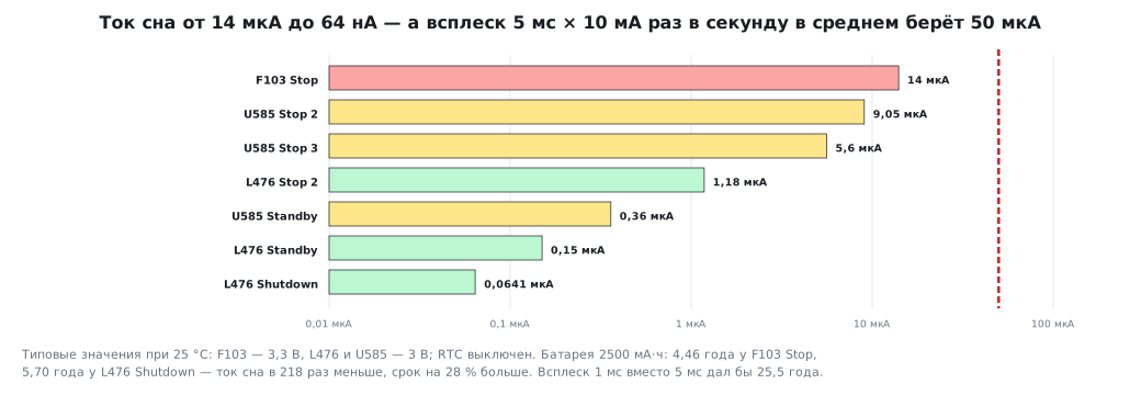
The sensor from 10.8: once a second it wakes up for 5 ms and draws 10 mA, the battery is 2500 mAh. The average current is by the same formula:
| Sleep | Sleep current | Average current | Battery life |
|---|---|---|---|
| F103 Stop | 14 µA | 63.93 µA | 4.46 years |
| U585 Stop 2 | 9.05 µA | 59.00 µA | 4.84 years |
| U585 Stop 3 | 5.60 µA | 55.57 µA | 5.14 years |
| L476 Stop 2 | 1.18 µA | 51.17 µA | 5.58 years |
| L476 Standby | 150 nA | 50.15 µA | 5.69 years |
| L476 Shutdown | 64.1 nA | 50.06 µA | 5.70 years |
The sleep current fell 218 times, but the life grew from 4.46 to 5.70 years — by 28 %. A burst of 5 ms × 10 mA once a second by itself gives 50 µA of average current, and no sleep mode will reduce it. Shorten the burst to 1 ms — and L476 in Stop 2 gives 11.18 µA on average and 25.5 years; at such a life the limit is already the self-discharge of the battery, not the chip.
Hence the order of work, the same as in 10.8: first squeeze the active part — fewer cycles, a shorter measurement, rarer wake-ups — then choose the sleep mode. Standby instead of Stop 2 wins 0.11 years here, but turns every wake-up into a reset with initialisation, and that itself lengthens the burst.
10а.5 Entering Stop 2, Standby with SRAM2 and Stop 3
On L4 the mode is selected by the LPMS field in PWR_CR1, as on G0 in 10.9, and entered
with the same WFI with SLEEPDEEP set:
void stop2_enter(void)
{
    RCC->APB1ENR1 |= RCC_APB1ENR1_PWREN;
    RCC->CFGR |= RCC_CFGR_STOPWUCK;                 /* проснуться на HSI16, а не на MSI */
    PWR->CR1 = (PWR->CR1 & ~PWR_CR1_LPMS) | PWR_CR1_LPMS_STOP2;
    SCB->SCR |= SCB_SCR_SLEEPDEEP_Msk;
    __DSB();
    __WFI();                                        /* спим; будит RTC или LPUART1 */
    SCB->SCR &= ~SCB_SCR_SLEEPDEEP_Msk;             /* дальше WFI — снова обычный Sleep */
}

void standby_keep_sram2(void)
{
    RCC->APB1ENR1 |= RCC_APB1ENR1_PWREN;
    PWR->CR3 |= PWR_CR3_RRS;                        /* SRAM2 живёт в Standby: +236 нА */
    PWR->SCR = PWR_SCR_CWUF;                        /* сбросить старые флаги пробуждения */
    PWR->CR1 = (PWR->CR1 & ~PWR_CR1_LPMS) | PWR_CR1_LPMS_STANDBY;
    SCB->SCR |= SCB_SCR_SLEEPDEEP_Msk;
    __DSB();
    __WFI();                                        /* выход — через сброс */
}
After Stop 2 the core wakes up not at the previous frequency but on an internal
oscillator: the STOPWUCK bit selects HSI16 instead of MSI. The PLL and the external
crystal are switched on again after wake-up, as after Stop on F103.
U585 has the same LPMS field, but more values: 011 — Stop 3
(RM0456, the description of PWR_CR1):
void stop3_enter(void)
{
    RCC->AHB3ENR |= RCC_AHB3ENR_PWREN;
    RCC->CFGR1 |= RCC_CFGR1_STOPWUCK;               /* проснуться на HSI16 */
    PWR->CR1 = (PWR->CR1 & ~PWR_CR1_LPMS) | PWR_CR1_LPMS_0 | PWR_CR1_LPMS_1;   /* 011 — Stop 3 */
    SCB->SCR |= SCB_SCR_SLEEPDEEP_Msk;
    __DSB();
    __WFI();
    SCB->SCR &= ~SCB_SCR_SLEEPDEEP_Msk;
}
10а.6 Who works during sleep: LPUART and LPTIM
In Stop 2 all core clocks are stopped, but a few blocks are made so as to live without them. LPUART1 on the 32 768 Hz watch crystal receives up to 9600 baud (RM0351) and wakes the core when a byte arrives; for a higher speed it is clocked from HSI16 — in Stop it switches the oscillator on by itself for the duration of a frame and switches it off if the frame is not addressed to the device. LPTIM1 counts pulses or time from LSE, the RTC wakes on an alarm. This way a device listens to a line or counts the pulses of a water meter while drawing a few microamperes, and wakes up fully only when there is a reason.
Ordinary USART, SPI, I²C (except I2C3), timers and the ADC do not work in Stop 2: they need a clock signal that is not there. If the device must receive at 115 200 baud — this is Stop 0 or Sleep, and in Stop 2 only LPUART1 from HSI16: the oscillator is switched on for each frame, and the sleep current grows.
10а.7 Pitfalls
- Calculating at 25 °C. At 85 °C Stop 2 on L476 takes 15.4 µA instead of 1.18. The battery budget is calculated for the temperature where the device lives.
- Hunting for nanoamperes while the burst is large. Shutdown instead of Stop 2 wins 0.12 years, while a 1 ms burst instead of 5 wins twenty years.
- Retaining all RAM on U5. Stop 2 with full RAM is 20.5 µA against 9.05 with SRAM2 alone. Only the needed banks are retained.
- Expecting the previous frequency after Stop. The core wakes up on HSI16 or MSI; the PLL and HSE are started again, otherwise the UART and timers count wrongly.
- Entering Stop 2 from Low-power run. RM0351: Stop 2 is entered only from the ordinary Run mode.
- Shutdown without supply monitoring. BOR does not work in it; if the supply sags during sleep, the chip will learn about it only after wake-up.
- Receiving 115 200 baud in Stop 2 on LSE. LPUART on LSE is up to 9600 baud; faster — only from HSI16, which switches on for each frame.
- Leaving pins floating in Standby and Shutdown. The outputs are released there,
and a load switch may turn on by itself. The levels are held by pull resistors: the
APCbit and the registersPWR_PUCRx,PWR_PDCRx. - Measuring with the debugger connected. The debugger keeps domains powered, and the sleep current with ST-Link connected is not representative — measure without it, as in 10.8.
10а.8 Summary
- L476 at 3 V, 25 °C: Stop 2 — 1.18 µA (with the RTC on the crystal — 1.67), Standby — 150 nA, SRAM2 in Standby — plus 236 nA, Shutdown — 64.1 nA. Wake-up from Stop 2 — 7.3 µs, from Standby — 14.3 µs, from Shutdown — 256 µs.
- F103: Stop — 14 µA, Standby — 2 µA at 3.3 V.
- At 85 °C Stop 2 on L476 is 15.4 µA, 13 times more.
- U585 leaks more: Stop 2 — 9.05 µA with SRAM2 alone and 20.5 µA with all RAM, Stop 3 — 5.60 µA, Standby — 0.36 µA.
- The sensor from 10.8: from 4.46 years on F103 to 5.70 years on L476 in Shutdown — the sleep current is 218 times lower, the life is 28 % longer. A burst of 1 ms instead of 5 gives 25.5 years.
- The mode is selected by the
LPMSfield inPWR_CR1; after Stop the core runs on HSI16 or MSI (STOPWUCK). - In Stop 2 LPUART1 (up to 9600 baud on LSE), LPTIM1, I2C3 and the RTC work.
Full sources
lp10a.c — entering Stop 2 and Standby with SRAM2 retention on L476 and Stop 3 on U585.
/* 10а: вход в Stop 2 и в Standby с сохранением SRAM2 (L476), Stop 3 (U585).
   Собирается armclang для STM32L476 и STM32U585 (проверка _verify/lp10a_check.py). */
#include <stdint.h>

#if defined(STM32L476xx)
void stop2_enter(void)
{
    RCC->APB1ENR1 |= RCC_APB1ENR1_PWREN;
    RCC->CFGR |= RCC_CFGR_STOPWUCK;                 /* проснуться на HSI16, а не на MSI */
    PWR->CR1 = (PWR->CR1 & ~PWR_CR1_LPMS) | PWR_CR1_LPMS_STOP2;
    SCB->SCR |= SCB_SCR_SLEEPDEEP_Msk;
    __DSB();
    __WFI();                                        /* спим; будит RTC или LPUART1 */
    SCB->SCR &= ~SCB_SCR_SLEEPDEEP_Msk;             /* дальше WFI — снова обычный Sleep */
}

void standby_keep_sram2(void)
{
    RCC->APB1ENR1 |= RCC_APB1ENR1_PWREN;
    PWR->CR3 |= PWR_CR3_RRS;                        /* SRAM2 живёт в Standby: +236 нА */
    PWR->SCR = PWR_SCR_CWUF;                        /* сбросить старые флаги пробуждения */
    PWR->CR1 = (PWR->CR1 & ~PWR_CR1_LPMS) | PWR_CR1_LPMS_STANDBY;
    SCB->SCR |= SCB_SCR_SLEEPDEEP_Msk;
    __DSB();
    __WFI();                                        /* выход — через сброс */
}
#endif

#if defined(STM32U585xx)
void stop3_enter(void)
{
    RCC->AHB3ENR |= RCC_AHB3ENR_PWREN;
    RCC->CFGR1 |= RCC_CFGR1_STOPWUCK;               /* проснуться на HSI16 */
    PWR->CR1 = (PWR->CR1 & ~PWR_CR1_LPMS) | PWR_CR1_LPMS_0 | PWR_CR1_LPMS_1;   /* 011 — Stop 3 */
    SCB->SCR |= SCB_SCR_SLEEPDEEP_Msk;
    __DSB();
    __WFI();
    SCB->SCR &= ~SCB_SCR_SLEEPDEEP_Msk;
}
#endif
Next: section 10б "LPBAM on STM32U5" — the timer, the ADC and the transfer controller work in Stop 2 by themselves, and the core is woken once per block.