 Embedded HandbookApps
192. Peripherals from a program: gpiochip, i2c-dev, spidev, sysfs
On a microcontroller you toggle a pin by writing to a register: GPIOC->BSRR
and you are done (section 8). On a Linux device the kernel owns the registers, and a program
asks it for a service through a file in /dev. The difference is not complexity
but who is responsible for the hardware — and this section shows what
the same work looks like from the other side.
The numbers come from the Debian 12 kernel headers, by running _verify/linux191/uapi.c
in the stm-linux:1 image; _verify/linux191_check.py checks them.
Terms used in the documentation
Term Meaning userspace user space: your processes, not the kernel character device a file in /devthat you talk to throughioctlioctl a command to a device outside read/write line (GPIO) one pin of a GPIO controller consumer who has taken the line: a name visible in the system line bias (GPIO) pull-up or pull-down of a line inside the controller
192.1 Who owns the pin
A program cannot write to the GPIO registers, and this is not a ban for the sake of a ban. The kernel needs to know who has taken a pin: otherwise two processes will drive the same LED at once, and the I²C bus driver will find that someone has toggled its pin by hand.
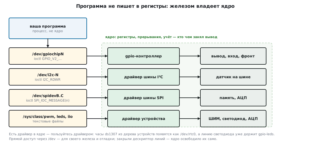
| What you need | File | How you access it |
|---|---|---|
| output, input, edge interrupt | /dev/gpiochipN |
ioctl, API version 2 |
| raw I²C bus | /dev/i2c-N |
ioctl I2C_SLAVE and I2C_RDWR |
| raw SPI bus | /dev/spidevB.C |
ioctl SPI_IOC_MESSAGE(n) |
| PWM, LEDs, ADC | /sys/class/pwm, leds, iio |
reading and writing text files |
A rule that saves days: if the device has a driver in the kernel,
use the driver, not direct bus access. The ds1307 clock from
the device tree (section 191.3) shows up as /dev/rtc0 by itself, and you do not need to read it
through i2c-dev. Direct access is for what the kernel does not have:
your own chip, debugging, a one-off check.
192.2 GPIO: /dev/gpiochipN
The old way through /sys/class/gpio (writing a number to export) is
deprecated: the line number there is global and shifts from kernel to kernel,
and nobody frees a forgotten line. The current way is a character device
per controller and requesting lines through ioctl.
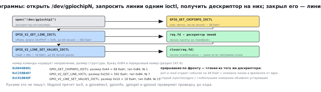
The order is: open /dev/gpiochipN, find out which controller it is,
request the lines you need in one request, get back a file
descriptor for the lines themselves and work with it from then on. Close the descriptor —
the lines are released by themselves, even if the program crashed.
#include <linux/gpio.h>

int chip = open("/dev/gpiochip1", O_RDWR);

struct gpiochip_info info;
ioctl(chip, GPIO_GET_CHIPINFO_IOCTL, &info);      /* имя, метка, сколько линий */

struct gpio_v2_line_request req = {0};
req.offsets[0] = 21;                               /* линия, которую дерево назвало, но не отдало драйверу */
req.num_lines  = 1;
req.config.flags = GPIO_V2_LINE_FLAG_OUTPUT;
strncpy(req.consumer, "handbook", sizeof(req.consumer) - 1);
ioctl(chip, GPIO_V2_GET_LINE_IOCTL, &req);         /* req.fd — дескриптор линий */

struct gpio_v2_line_values v = { .mask = 1, .bits = 1 };
ioctl(req.fd, GPIO_V2_LINE_SET_VALUES_IOCTL, &v);  /* зажечь */
v.bits = 0;
ioctl(req.fd, GPIO_V2_LINE_SET_VALUES_IOCTL, &v);  /* погасить */
close(req.fd);                                     /* линия свободна */
What is behind it, from the kernel headers:
| Value | What it is |
|---|---|
GPIO_GET_CHIPINFO_IOCTL = 0x8044B401 |
ask for the controller name and number of lines |
GPIO_V2_GET_LINEINFO_IOCTL = 0xC100B405 |
ask about one line: whether it is taken and by whom |
GPIO_V2_GET_LINE_IOCTL = 0xC250B407 |
request lines and get a descriptor |
GPIO_V2_LINE_GET_VALUES_IOCTL = 0xC010B40E |
read values |
GPIO_V2_LINE_SET_VALUES_IOCTL = 0xC010B40F |
write values |
struct gpiochip_info |
68 bytes |
struct gpio_v2_line_info |
256 bytes |
struct gpio_v2_line_request |
592 bytes |
struct gpio_v2_line_event |
48 bytes |
GPIO_V2_LINES_MAX |
64 lines per request |
The configuration flags are the same concepts as in the microcontroller registers
(section 8.2): GPIO_V2_LINE_FLAG_INPUT = 0x4,
GPIO_V2_LINE_FLAG_OUTPUT = 0x8,
GPIO_V2_LINE_FLAG_EDGE_RISING = 0x10,
GPIO_V2_LINE_FLAG_BIAS_PULL_UP = 0x100.
Values are passed not one line at a time but as a mask: mask says which lines
you touch, bits says what to write to them. The whole structure is 16 bytes,
and one call switches up to 64 lines at once.
An edge interrupt looks like reading from the same descriptor:
you request the line with the EDGE_RISING (or FALLING) flag, and then
poll and read return a 48-byte structure per event — with the line
number and a timestamp from the kernel's monotonic clock. This is a direct counterpart of
EXTI from section 7, except that the kernel stamps the time, not you.
In practice nobody writes all this by hand; you use libgpiod: the library hides
the ioctl calls, and its commands gpiodetect, gpioinfo, gpioget, gpioset
let you check the wiring before writing any code — exactly what you
usually lack on a microcontroller.
192.3 I²C: /dev/i2c-N
The bus is opened as a file. Then there are two ways: the simple one — tell the kernel the slave
address and use read/write; the right one — pass a pair of
messages in one call.
#include <linux/i2c.h>
#include <linux/i2c-dev.h>
int fd = open("/dev/i2c-0", O_RDWR);
uint8_t reg = 0x75, val = 0;
struct i2c_msg msgs[2] = {
{ .addr = 0x68, .flags = 0, .len = 1, .buf = ® }, /* записали номер регистра */
{ .addr = 0x68, .flags = I2C_M_RD, .len = 1, .buf = &val }, /* прочитали байт */
};
struct i2c_rdwr_ioctl_data tr = { .msgs = msgs, .nmsgs = 2 };
ioctl(fd, I2C_RDWR, &tr);
This is the same repeated-start transaction as in section 17.4, except that the controller driver produces the start, the address and the acknowledges.
| Value | What it is |
|---|---|
I2C_SLAVE = 0x703 |
set the slave address for read/write |
I2C_SLAVE_FORCE = 0x706 |
the same, even if a driver has taken the address |
I2C_TENBIT = 0x704 |
ten-bit addressing (section 17.2) |
I2C_RDWR = 0x707 |
several messages in one transaction |
I2C_RETRIES = 0x701, I2C_TIMEOUT = 0x702 |
how many retries and how long to wait |
struct i2c_msg |
16 bytes on a 64-bit system, 12 on the device's 32-bit ARM |
I2C_RDWR_IOCTL_MAX_MSGS |
42 messages per call |
I2C_M_RD = 0x1, I2C_M_TEN = 0x10 |
read; ten-bit address |
The address is seven-bit. You put 0x68 into addr, not 0xD0: the driver adds the shift
and the direction bit. This is exactly the confusion that
section 17.2 talks about — but here the kernel resolves it for you.
⚠️
I2C_SLAVEfails if a kernel driver has already taken the address. This is not a bug but a protection: theds1307clock from the device tree is held by thertcdriver. Either use the driver, or remove the device from the tree, or (for debugging) useI2C_SLAVE_FORCE— knowing that two parties will be talking to one chip.
192.4 SPI: /dev/spidevB.C
The file name is the bus number and the chip select number: spidev0.0 is the first
bus, the first CS. A transfer is always an exchange: as many bytes as you sent, so many
you receive (section 18.1).
#include <linux/spi/spidev.h>

int fd = open("/dev/spidev0.0", O_RDWR);
uint8_t mode = SPI_MODE_0, bits = 8;
uint32_t speed = 24000000;
ioctl(fd, SPI_IOC_WR_MODE, &mode);
ioctl(fd, SPI_IOC_WR_BITS_PER_WORD, &bits);
ioctl(fd, SPI_IOC_WR_MAX_SPEED_HZ, &speed);

uint8_t tx[3] = { 0x9F, 0, 0 }, rx[3] = { 0 };     /* JEDEC ID памяти, раздел 41 */
struct spi_ioc_transfer t = {
    .tx_buf = (unsigned long)tx,
    .rx_buf = (unsigned long)rx,
    .len = sizeof(tx),
    .speed_hz = speed,
    .bits_per_word = bits,
};
ioctl(fd, SPI_IOC_MESSAGE(1), &t);
| Value | What it is |
|---|---|
struct spi_ioc_transfer |
32 bytes |
SPI_IOC_WR_MODE = 0x40016B01, SPI_IOC_RD_MODE = 0x80016B01 |
set and read the mode |
SPI_IOC_WR_BITS_PER_WORD = 0x40016B03 |
bits per word |
SPI_IOC_WR_MAX_SPEED_HZ = 0x40046B04 |
maximum frequency |
SPI_IOC_MESSAGE(1) = 0x40206B00 |
one transfer |
SPI_IOC_MESSAGE(2) = 0x40406B00 |
two in a row, without releasing CS between them |
SPI_CPHA = 0x1, SPI_CPOL = 0x2 |
the same two bits as in the microcontroller's CR1 |
SPI_MODE_0 = 0x0, SPI_MODE_3 = 0x3 |
the modes from the table in section 18.2 |
SPI_3WIRE = 0x10 |
half duplex on one data line |
Note the numbers of SPI_IOC_MESSAGE(1) and SPI_IOC_MESSAGE(2):
they differ — 0x40206B00 and 0x40406B00. The ioctl number includes
the size of the data passed, and that is 32 × n: 0x20 and 0x40.
Hence the rule: the number in SPI_IOC_MESSAGE(n) must match the length
of the array of structures. The driver reads exactly n structures: with a smaller n the extra
transfers are silently skipped, with a larger one it reads the memory past the array,
and the result depends on the garbage — EINVAL, EFAULT or a strange transfer.
192.5 What stayed in sysfs
Not everything moved to character devices. Some peripherals are controlled through text files, and that is convenient: it works from the command line and from any language.
| Where | What it does |
|---|---|
/sys/class/pwm/pwmchip0/ |
export, then period and duty_cycle in nanoseconds, enable |
/sys/class/leds/<name>/ |
brightness, and trigger can blink by itself: heartbeat, timer |
/sys/bus/iio/devices/ |
ADCs, sensors: a raw value and a scale factor to convert to volts |
/sys/class/thermal/ |
die temperature in thousandths of a degree |
Here PWM is set by the period and the high time in nanoseconds,
not by PSC, ARR and CCR values (section 13.5): the driver does the
conversion. An LED from the device tree of section 191.3 with
linux,default-trigger = "heartbeat" starts blinking by itself, without a single
line of code — a handy "the system is alive" sign.
192.6 Pitfalls
You opened /dev/gpiochip0 and did not find the line you need. There are
several controllers, and each has its own numbering. gpiodetect shows the
controllers, gpioinfo shows the lines with their names and who has taken them.
The line is busy. A driver holds it (an LED, a bus, a sensor) from the device tree. You can free it only by removing the node from the tree — not by "force".
You wrote a value, but the pin did not change. In gpio_v2_line_values
you forgot mask: without a bit in the mask the kernel does not touch the line.
The line goes off right after the write. You closed the descriptor — the kernel returned the line to its initial state. Keep the descriptor open for as long as you need the level.
ioctl on SPI returns EINVAL or sends the wrong data. The number
in SPI_IOC_MESSAGE(n) does not match the number of structures: the ioctl number
is computed from the size, and the driver reads exactly n structures.
The I²C address is wrong. addr takes the seven-bit address; the eight-bit one
from the sensor datasheet addresses a different device.
Permissions. By default /dev/gpiochip* and /dev/spidev* often belong
to root, and the gpio and spi groups may not exist at all. You create the group, give
it the device with a udev rule (section 193.5), and add the service user
to it — with usermod -aG or a SupplementaryGroups= line. You do not need to run the device
as root just for an LED.
192.7 Summary
- The kernel owns the registers; a program works through files in
/devandioctl. This is not a workaround but a way not to fight over a pin. - GPIO:
/dev/gpiochipNand API version 2: a line request returns a descriptor, closing it frees the lines.struct gpio_v2_line_requestis 592 bytes, up to 64 lines at a time, values as a mask in 16 bytes. - An edge interrupt is reading 48-byte events with a timestamp from the kernel.
- I²C:
/dev/i2c-N:I2C_RDWR=0x707passes up to 42 messages in one transaction; the address is seven-bit, the driver does the shift. - SPI:
/dev/spidevB.C:struct spi_ioc_transferis 32 bytes,SPI_IOC_MESSAGE(n)encodes the size in the number itself —0x40206B00for one transfer and0x40406B00for two. - PWM, LEDs and ADCs stayed in
sysfsand are set with text: period and duty cycle in nanoseconds instead ofPSC/ARR/CCR. - If the hardware has a driver in the kernel, use the driver; direct access is for your own chips and for debugging.
Next: section 193 "Device service: systemd, journal, permissions and watchdog".