 Embedded HandbookApps
104а. Soldering iron on STM32: inside IronOS — a thermocouple in the tip, PID and USB Power Delivery
In section 104 the thermocouple was read by a ready-made chip: the MAX31855 amplifies the microvolts itself, measures the cold junction itself and returns degrees over SPI. A soldering iron tip has no such chip. The thermocouple there is a junction of two metals right next to the heater, and it shares its wires with the heater. While heating current flows through them, there is nothing to measure; you can only measure in the pause.
This section takes apart the open firmware IronOS — the one that runs on the soldering irons TS100, TS80, Pinecil and others. We look at how it splits the PWM period into heating and measurement, how it converts the ADC code to degrees, which controller holds the temperature, how it picks a voltage from a USB PD charger and what it does when something breaks. The real firmware functions were built on a computer and run against a model of the tip: heating from 25 to 320 °C, a load, a removed tip, a shorted thermocouple.
References: the IronOS sources (github.com/Ralim/IronOS, snapshot 2e1f8c2,
version v2.23) — paths below are relative to the source/Core directory;
the RM0008 reference manual for F103 clocking. Thermocouple and cold junction —
section 104, the controller — section 47, timer and PWM — section 13, ADC
and injected channels — section 14, FreeRTOS — sections 24–34.
License: IronOS is distributed under GPL-3.0. The code fragments below are short quotations with the file named; copies of the files used sit next to the check together with the license text.
Terms used in the documentation
Term Meaning tip the replaceable working end of the iron heater the heating element inside the tip cold junction compensation (CJC) correction for the cold junction op-amp gain stage amplifier stage built on an op-amp injected channels ADC channels converted by a separate trigger lookup table conversion table thermal runaway uncontrolled heating power data object (PDO) one offer from a USB PD source sleep / shutdown sleep / switching off keep awake pulse "do not fall asleep" pulse for a power bank
104а.1 What the firmware is and what it runs on
IronOS started as a replacement for the stock TS100 firmware; now it is a common
firmware for a dozen soldering irons and two hot plates. Which
microcontroller sits in which device can be seen in the Makefile: for
each model it has its own compiler flags and a board directory in BSP/.
| Device | Microcontroller | Power (per README) | Board directory |
|---|---|---|---|
| Miniware TS100 | STM32F103 | DC | BSP/Miniware |
| Miniware TS80, TS80P | STM32F103 | QC; TS80P also PD | BSP/Miniware |
| Miniware TS101 | STM32F103 (a clone, says Hardware.md) | DC, PD | BSP/Miniware |
| Sequre S60, S60P, S99, T55 plate | STM32F103 | PD; S99 also DC | BSP/Sequre |
| Miniware MHP30 (plate) | STM32F103 | PD | BSP/MHP30 |
| Pine64 Pinecil V1 | GD32VF103 (RISC-V) | DC, QC, PD | BSP/Pinecil |
| Pine64 Pinecil V2 | BL706 (RISC-V) | DC, QC, PD | BSP/Pinecilv2 |
Everything that does not depend on the board is shared: Threads/PIDThread.cpp (the controller),
Threads/MOVThread.cpp (the accelerometer), Drivers/TipThermoModel.cpp
(degrees), Src/power.cpp (watts to PWM), Drivers/USBPD.cpp (voltage
selection). The board provides the timers, the ADC, the thermocouple table and the constants
in its configuration.h. Everything runs under FreeRTOS with a 1000 Hz tick.
From here on we look at the TS100: it has an STM32F103, a published schematic and the simplest signal path. Where the Pinecil differs, this is noted.
Can the firmware be built offline? No. The standard make -k model=TS100
firmware-EN in an image with arm-none-eabi-gcc 12.2.1 built 122 object
files and stopped on three things: the settings generator needs the Python module
yaml, the font and translation generator needs bdflib, and four
accelerometer drivers need the <array> header from the C++ standard library
for ARM, which the image does not have. Without network access they cannot be installed, so there is
no firmware image. The controller files were built with the same flags (without
-flto, so that the object file contains machine code):
| File | Code (.text), bytes |
|---|---|
Threads/PIDThread.cpp |
760 |
BSP/Miniware/BSP.cpp |
500 |
BSP/Miniware/ThermoModel.cpp |
424 |
Drivers/TipThermoModel.cpp |
248 |
Src/power.cpp |
220 |
Drivers/Utils.cpp |
130 |
Of the 424 bytes of ThermoModel.cpp, 408 are a table of 51 points.
104а.2 Heating and measuring in turn
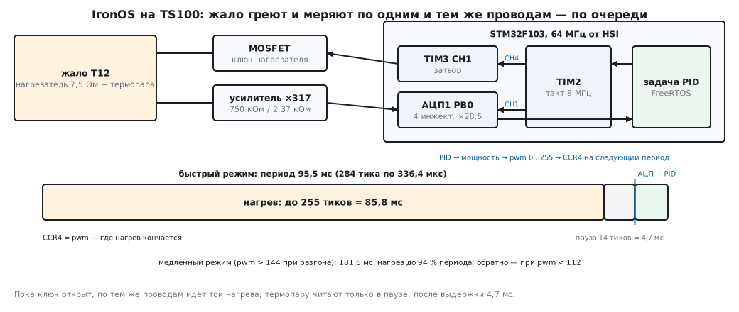
The F103 clock in the TS100 comes from the internal HSI oscillator: 8 MHz / 2 × 16 = 64 MHz. The APB1 bus is divided by 16, down to 4 MHz, and for timers on it RM0008 doubles the frequency if the bus prescaler is not 1 — hence 8 MHz for TIM2 and TIM3. The ADC clock is 64 / 6 = 10.67 MHz.
The whole "heat — pause — measure" cycle is driven by TIM2 (BSP/Miniware/BSP.cpp):
static void switchToFastPWM(void) {
  // 10Hz
  infastPWM              = true;
  totalPWM               = powerPWM + tempMeasureTicks + holdoffTicks;
  htimADC.Instance->ARR  = totalPWM;
  htimADC.Instance->CCR1 = powerPWM + holdoffTicks;
  htimADC.Instance->PSC  = 2690;
}
powerPWM = 255; the pause holdoffTicks and the measurement window
tempMeasureTicks are 14 ticks each. A timer tick is 2691 / 8 MHz = 336.4 µs,
the period is 284 ticks, 95.5 ms, 10.47 Hz. At the start of the period the
update interrupt handler switches heating on, and channel CH4 with the value pwm
switches it off, so heating takes 0 to 255 ticks, up to 85.8 ms. Channel
CH1 at tick 269 (90.5 ms) starts the ADC1 injected sequence via TRGO:
four conversions of input PB0 at 28.5 cycles each, in total 4 × (28.5 + 12.5) =
164 cycles, 15.4 µs. Between the end of the longest heating pulse and the measurement
there are 14 ticks, 4.71 ms: a comment in Setup.cpp says the amplifier output
needs 4 ms to settle after switch-off. The "sequence done" interrupt
wakes the PID task, which computes the new power, and the new
pulse width takes effect from the next period.
The more often you measure, the less time is left for heating. That is why there are two
modes. Slow: prescaler 5380, a period of 270 ticks of 672.6 µs = 181.6 ms,
5.51 Hz, the same 4.71 ms pause, and heating can take 94.4 % of the period instead of
89.8 %. Src/power.cpp switches to the slow mode when the pulse width
exceeds 144 and returns to the fast mode below 112 — hysteresis, so it does not
flip back and forth. In the run below, while heating up the tip, the firmware switched modes
twice: to slow on the very first cycle and back at about 320 °C; in the first
3 s it measured the tip 17 times.
The heater switch in the TS100 is not driven by the timer pin directly. TIM3 outputs a
50 % square wave on PB4, and that, according to a comment in Setup.cpp, goes to the gate through
a capacitor — a steady level does not pass through a capacitor. TIM2 only
turns this square wave on and off. The second safeguard is the counter
PWMSafetyTimer: the PID task sets it to 20 on every call, every
timer period decrements it, and at zero heating is not switched on. If the task
hangs, the tip cools down after 20 periods — 1.91 s in fast mode
and 3.63 s in slow mode.
104а.3 From ADC code to degrees
The thermocouple in the tip gives very little: at 320 °C with the handle at 25 °C, about 6924 µV according to
the firmware's table. The op-amp stage amplifies this by 1 + 750 kΩ / 2.37 kΩ.
Four 12-bit conversions are added up and shifted left by one bit,
so full scale is 32768 (ADC_MAX_READING), which is 3.3 V. Then comes
Drivers/TipThermoModel.cpp:
  uint32_t rawInputmVX10 = (rawADC * vddRailmVX10) / (ADC_MAX_READING);

  uint32_t valueuV = rawInputmVX10 * 100; // shift into uV
  // Now to divide this down by the gain
  valueuV /= OP_AMP_GAIN_STAGE;
The offset CalibrationOffset is subtracted from the microvolts — 900 µV by
default, the sum of the op-amp offset and the pull-up on the input. Then the table
BSP/Miniware/ThermoModel.cpp: 51 "microvolts — degrees" pairs from 0 to
500 °C in steps of 10 °C, for Hakko T12 style tips (0 µV — 0 °C, 7609 µV —
320 °C, 12575 µV — 500 °C). Between points it is a straight line; past the last one
the last segment is extended: 13000 µV gives 517 °C.
The cold junction here is the handle. In the TS100 it has a TMP36 sensor, and its degrees
are simply added to the degrees from the table. This is cruder than in section 104:
degrees are added, not thermoelectric voltages. The IronOS documentation
(Documentation/Temperature.md) admits this: the remaining error is treated as
a constant offset, and near room temperature the reading may
jump. The offset is adjusted by the calibration at power-on (CJC.cpp):
if the tip and the handle differ by less than 10 °C, the firmware takes
16 measurements and stores their average in microvolts as the new offset.
The real firmware code, built on a computer, on a model of the amplifier and ADC (handle 25 °C, offset 900 µV):
| Tip | ADC code | Sum | Firmware computed | Actual per table | Reading |
|---|---|---|---|---|---|
| 100 °C | 1066 | 8528 | 1809 µV | 1807 µV | 100 °C |
| 200 °C | 1921 | 15368 | 3982 µV | 3976 µV | 200 °C |
| 320 °C | 3082 | 24656 | 6932 µV | 6924 µV | 320 °C |
| 400 °C | 3969 | 31752 | 9187 µV | 9174 µV | 400 °C |
| 430 °C | 4095 | 32760 | 9507 µV | 10040 µV | 411 °C |
Two things are clear at once. First, OP_AMP_GAIN_STAGE is computed
by the preprocessor in integers: 1 + 750000 / 2370 = 317, while from the resistors it is 317.46.
The firmware overstates the microvolts by 0.15 %, at 320 °C by 8 µV, less than
a degree. Second, one unit of the sum is 100.7 µV at the amplifier output
and 0.318 µV at the thermocouple: that is why the built-in ADC has the precision
it lacked in section 104 — the amplifier does all the work.
The scale, however, is short. At 430 °C the ADC is already at its ceiling (4095), and the firmware
sees 411 °C. getTipMaxInC() with the handle at 25 °C returns 410 °C, and
the PID task clamps the setpoint to that value: the menu lets you choose
up to 450 °C, but the TS100 will hold no more than 410.
104а.4 The controller: a leaky integrator instead of PID
Threads/PIDThread.cpp has two controllers. A real PID is enabled by
TIP_CONTROL_PID, and in this snapshot it is defined only for the Pinecil V2:
Kp 40, Ki 6, Kd 200 (configuration_Pinecilv2.h). All other devices,
the TS100 included, run on a leaky integrator:
    sum = (sum * (100 - (inertia / rate))) / 100;
    // Add the new value x integration interval ( 1 / rate)
    sum += (gain * val) / rate;
The input is val = 65 × (setpoint − reading); 65 is TIP_THERMAL_MASS
in tenths of a watt per degree per second; inertia is also 65, gain is 2,
rate is how many times per second the controller is called, as an integer: 1000 / 95 = 10
in fast mode, 1000 / 181 = 5 in slow mode. The output is power in tenths of
a watt, clamped to ± the power limit.
If you expand the integer arithmetic, in fast mode each cycle the sum is multiplied by 94/100 and 13 × error is added to it. The 6 % leak per cycle keeps the integral from accumulating: in steady state the sum equals 13 / 0.06 = 216.7 tenths of a watt per degree of error, that is 21.67 W/°C. In slow mode it is × 87/100 and 26 × error, 20.00 W/°C. In essence this is a P controller with high gain and smoothing over time, not an integral. The author explains the choice in the "Sandman note" comment: right after a pulse the heater is hotter than the tip, the instantaneous reading is too high, and a leaky controller behaves like P far from the setpoint and almost like I near it.
This also gives the steady-state error, as in section 47.2. To hold 5.9 W you need 0.27 °C of underheating, and degrees in the firmware are integers. In the run the tip stayed at 319…320 °C, 319.69 on average.
The tip model for the run. Its parameters are our assumptions, not
TS100 data: two nodes — the heater with the thermocouple (0.25 J/°C) and the tip body
(1.44 J/°C); together 1.69 J/°C — the value that, according to a comment in power.hpp,
the author measured on his tip. Between the nodes, 1 K/W — so that the body catches up with
the heater in 3–5 s, as Temperature.md says. Losses to air
0.02 W/K, 24 V supply, a 7.5 Ω heater, handle at 25 °C. The timer, the ADC
and the controller calls are as in section 104а.2.
| Run, setpoint 320 °C | Integrator (TS100) | PID with Pinecil V2 constants |
|---|---|---|
| Reading first reaches 320 °C | 5.99 s | 7.10 s |
| Reading peak | 323 °C (+3) | 322 °C (+2) |
| Within the ±2 °C band from | 6.36 s | 10.32 s |
| Tip body within 5 °C of its final value | 8.98 s | 10.41 s |
| Reading over 50…60 s | 319…320, average 319.69 | 319…320, average 319.38 |
| PWM mode switches | 2 | 20 |
| Load 0.1 W/K for 5 s: reading minimum | 317 °C | 313 °C |
| Under load, average over the last 2 s | 318.48 °C at 30.9 W | 313.48 °C at 29.5 W |
The controller holds the temperature of the heater, not of the tip end: in steady state the tip body in the model is 5 °C cooler (314.8 °C with 319.7 °C at the heater) — exactly the losses, 5.9 W × 1 K/W. Under load the difference grows: the reading minimum is 317 °C, the body minimum is 290.3 °C. This is true of any soldering iron with the sensor at the heater. The Pinecil V2 PID on the TS100 signal path is shown only for comparison: IronOS does not build the TS100 this way. After the load was removed, the integrator never left the ±2 °C band, while the PID returned to it at 37.16 s — 2.16 s later.
104а.5 Power, PWM and USB PD
The controller outputs watts, but the timer needs a pulse width. Src/power.cpp
computes how much the tip would give with a pulse over the whole period:
uint32_t availableWattsX10 = (v * v) / tipResistance;
and multiplies it by the fraction of the period available for heating:
  availableWattsX10 = availableWattsX10 * powerPWM;
  availableWattsX10 /= totalPWM;
At 24 V and a 7.5 Ω tip this is 692 tenths of a watt in fast mode and 728 in slow mode. The required width is a proportion:
pwm = (powerPWM * x10Watts) / availableW10(sample);
5 W is 18 of 255, 10 W is 36, 30 W is 110, 69.2 W and above is 255. From above, the power is limited by the "power limit" setting (off by default on the TS100), by the agreement with the source, and on the S99 also by handle heating; in the run the limit equals the same 692.
On irons without a buck converter the current in a pulse is always V / R;
PWM changes only the average (Documentation/Hardware.md). So you must not ask
a USB PD source for a voltage at which V / R is greater than its current.
On the TS80P, TS101, MHP30 and both Pinecils (POW_PD 1 in configuration.h)
the negotiation is done by a FUSB302 chip over I²C (address 0x22 in USBPD.cpp)
and the usb-pd library by the same author; in the snapshot it is a git submodule, and its
directory is empty. Sequre devices use ready-made HUB238 or FS2711 sinks instead
(POW_PD_EXT). The selection rule for the FUSB302 is in Drivers/USBPD.cpp:
      int min_resistance_ohmsx10 = voltage_mv / current_a_x100;
      if (voltage_mv > 0) {
        if (voltage_mv <= (USB_PD_VMAX * 1000)) {
          if (voltage_mv <= 20000 || (pd_mode != usbpdMode_t::NO_DYNAMIC)) {
            if (min_resistance_ohmsx10 <= tipResistance) {
Of the suitable fixed offers, the one with the highest
voltage is taken. The default PD mode is 0, NO_DYNAMIC: fixed
voltages only and no higher than 20 V, even if the board's USB_PD_VMAX is 28 (Pinecil V2,
TS101). In DEFAULT mode 0.5 Ω of margin is added to the tip resistance
and PPS and EPR are allowed. Two examples for a 7.5 Ω tip, with the rule
reimplemented in Python:
| Power supply | 20 V: mV / (10 mA) | Selected | Power and current |
|---|---|---|---|
| 45 W: 5 V 3 A, 9 V 3 A, 15 V 3 A, 20 V 2.25 A | 20000 / 225 = 88 > 75 | 15 V | 30.0 W, 2.00 A |
| 65 W: 5 V 3 A, 9 V 3 A, 15 V 3 A, 20 V 3.25 A | 20000 / 325 = 61 ≤ 75 | 20 V | 53.3 W, 2.67 A |
At startup the PID task waits up to 3 s for the negotiation to finish and only then starts heating.
104а.6 Protections, sleep and the display
Thermal runaway. detectThermalRunaway() in PIDThread.cpp watches
for two signs. First: if heating has been on for more than 20 s and the difference
between the highest and lowest reading is less than 3 °C, the counter
heaterThermalRunawayCounter is incremented by 1 — once for the whole run time,
after which the check is disabled. Second: if heating is off and the ADC sum is
above ADC_MAX_READING - 8, the counter is incremented every cycle. Once a second
the counter is decremented by 1. Above 8, heating is switched off, and the soldering mode
(Soldering.cpp) shows the thermal runaway screen. Separately, heating
is cut if the ADC sum is above 0x7FFF - 32.
Tip removed. The pull-up on the input drives the amplifier to its ceiling, and the reading
shoots up. isTipDisconnected() considers the tip removed if
the reading is above getTipMaxInC() - 5. In the run the tip was "removed" at second
30: the very first reading was 411 °C, above the setpoint, and the controller cut
heating on the same cycle.
Sleep and shutdown. The MOVThread.cpp task reads the
accelerometer every 100 ms — the firmware detects by itself which one is fitted: MMA8652FC, LIS2DH12,
BMA223, SC7A20 or MSA301. Each reading is compared with the average of the last
eight; if the sum of deviations over the three axes exceeds a threshold, that counts as
movement. The threshold is 1500 + 9 × 200 − 200 × sensitivity; with the
default sensitivity of 7 it is 1900. After 50 s without movement or button presses, the iron goes to
sleep: the setpoint drops to 150 °C (or to the working one, if that is lower). After
10 min without movement, heating is switched off.
The display is an SSD1306 over I²C, address 0x3C; on the TS100 it is 96 × 16 pixels on a software bus, on the TS101 and Sequre devices it is 128 × 32.
104а.7 Pitfalls
Setpoint 320 °C, the display shows 319. A leaky controller holds the power only by means of the error: 5.9 W is 0.27 °C of underheating, and degrees are integers. In the run the average was 319.69 °C.
The TS100 does not heat above 410 °C. The ADC scale runs out: with the handle at 25 °C
getTipMaxInC() = 410 °C, and the setpoint is clamped to it, although the menu offers 450.
The reading is 320, but solder melts worse. The thermocouple is at the heater. In the model the tip body is 5 °C cooler without load, and under a load of 0.1 W/K its minimum is 290.3 °C with a reading minimum of 317 °C.
A shorted thermocouple is not caught. If the thermocouple gives 0 µV, the firmware
sees the handle temperature. In the run the reading stayed at 25 °C for 60 s,
the pulse width was 255, and the runaway counter remained 0: the highest
reading while heating is no greater than the lowest, and the difference check does not
fire. Sleep does not help: the sleep setpoint of 150 °C is still above
the 25 °C reading (Sleep.cpp). Heating is cut by the shutdown after 10 min
without movement, or by the person soldering.
The "ADC at ceiling" check is silent on the TS100. Four 12-bit conversions
with the shift give no more than 4095 × 8 = 32760, while the condition is strictly greater than
ADC_MAX_READING - 8, that is, greater than the same 32760. In the run with the tip
removed the sum stayed at 32760, and the counter remained 0. Heating is still
cut, but by a different path: the reading is above the setpoint.
A 45 W charger, and the iron takes 15 V. 20 V × 2.25 A is not suitable for a 7.5 Ω tip: the peak current 20 / 7.5 = 2.67 A is greater than 2.25 A. You need a supply with 3 A at 20 V.
The firmware does not build from the archive offline. The usb-pd submodule is empty,
the generators need yaml and bdflib, and the accelerometer drivers need
the C++ standard library for ARM.
The reading jumps near room temperature. The cold junction is accounted for by
adding the handle's degrees, and the remaining error is treated as constant
(Temperature.md); below 100 °C this is noticeable.
104а.8 Summary
- IronOS is open firmware (GPL-3.0) for the TS100, TS80(P), TS101, Sequre, MHP30 on the STM32F103 and the Pinecil on the GD32VF103 and BL706.
- Heating and measurement share the same wires and take turns: TIM2 splits the 95.5 ms period (fast mode) or 181.6 ms (slow mode) into heating of up to 255 ticks, a 4.71 ms pause and the injected ADC.
- ADC code → microvolts (gain 317, 0.318 µV per unit) → table of 51 points → plus the handle's degrees. The TS100 limit is 410 °C.
- The TS100 controller is a leaky integrator: 21.67 W/°C in fast mode, holds 319…320 °C at a setpoint of 320. PID (Kp 40, Ki 6, Kd 200) is only on the Pinecil V2.
- On the tip model: 320 °C in 5.99 s, peak +3 °C, ±2 °C band from 6.36 s.
- Watts → PWM via V² / R: at 24 V and 7.5 Ω the full width is 69.2 W. USB PD takes the highest voltage where V / I is no greater than the tip resistance: a 45 W supply gives 15 V, a 65 W supply gives 20 V.
- Protections: the thermal runaway counter (above 8 — stop), the 20-period safeguard, the removed tip; sleep after 50 s down to 150 °C, shutdown after 10 min. The firmware does not notice a shorted thermocouple.
Next: section 104б "MLX90614 IR thermometer over SMBus: contactless object temperature, PEC, emissivity and field of view" — temperature without touching: the MLX90614 catches the object's radiation, and emissivity and the field of view decide the accuracy.