 Embedded HandbookApps
104. Thermocouple: MAX31855 and MAX6675
The DS18B20 stops at +125 °C, a glass-bodied thermistor at 250–300 °C, but a furnace, a soldering iron or an exhaust needs a thermocouple. It is two wires of different alloys, welded together at the end. It does not measure temperature but a difference: a voltage appears between the hot junction and the point where its wires change to copper — the cold junction. For type K this is about 41 µV per degree. The MAX6675 and MAX31855 measure these microvolts, measure the cold-junction temperature themselves and return a ready number over SPI. What is left is to parse the frame — with the sign and the fault bits — and to correct the linear conversion that the MAX31855 uses in place of the real thermocouple characteristic.
The SPI bus is section 18, temperature up to +125 °C is section 96, the 24-bit sign is section 102, connecting modules is section 95.
Terms used in the documentation
Term Meaning thermocouple two wires of different alloys joined at one end hot junction, measuring junction the junction at the point being measured cold junction, reference junction where the thermocouple wires meet copper cold-junction compensation (CJC) adding the cold-junction temperature back in Seebeck coefficient microvolts per degree type K (chromel–alumel) the most common thermocouple type thermoelectric voltage, EMF the voltage the thermocouple produces extension wire thermocouple-alloy wire for extending the leads grounded / ungrounded junction junction tied to the sheath / insulated junction open circuit (OC) broken wire short to GND / VCC (SCG / SCV) short to ground / to the supply linearization correcting for non-linearity
104.1 The thermocouple and the cold junction
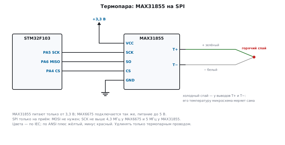
The thermocouple voltage is E(hot) − E(cold), where E is the standard thermoelectric voltage table for its type. For type K:
| Temperature | Thermoelectric voltage |
|---|---|
| −200 °C | −5.891 mV |
| −100 °C | −3.554 mV |
| 25 °C | 1.000 mV |
| 100 °C | 4.096 mV |
| 500 °C | 20.644 mV |
| 1000 °C | 41.276 mV |
So the converter measures two things: the thermocouple voltage and its own temperature — which is the cold-junction temperature, as long as the thermocouple wires run straight to its pins. A step of 0.25 °C is 10.3 µV: the microcontroller's built-in ADC cannot resolve a voltage that small.
104.2 Two converters
| MAX6675 | MAX31855K | |
|---|---|---|
| Frame | 16 bits | 32 bits |
| Temperature | 0 … 1023.75 °C, unsigned | −200 … +1350 °C for type K, signed |
| Step | 0.25 °C | 0.25 °C; cold junction 0.0625 °C |
| Faults | "no thermocouple" | open circuit, short to ground, short to supply |
| Supply | 3.0 … 5.5 V | 3.0 … 3.6 V |
| Conversion | up to 0.22 s | up to 0.1 s |
| SCK | up to 4.3 MHz | up to 5 MHz |
The MAX31855 is made for different thermocouple types — the letter at the end of the name tells you which; the MAX6675 is for type K only.
104.3 Receive-only SPI
Both chips only send: while CS is low, each SCK clock shifts out the next bit, MSB first. MOSI is not needed, but the microcontroller's SPI still transmits — just to generate the clocks. Mode 0, 16-bit frame:
void tc_spi_init(void)
{
#if defined(STM32F10X_MD)
    RCC->APB2ENR |= RCC_APB2ENR_IOPAEN | RCC_APB2ENR_SPI1EN;
    GPIOA->CRL = (GPIOA->CRL & ~0x0FFF0000u) | 0x04B30000u;         /* PA4 выход, PA5 альт. выход, PA6 вход */
#else
    RCC->AHB1ENR |= RCC_AHB1ENR_GPIOAEN;
    RCC->APB2ENR |= RCC_APB2ENR_SPI1EN;
    GPIOA->MODER = (GPIOA->MODER & ~0x3F00u) | 0x2900u;             /* PA4 выход, PA5 и PA6 — AF */
    GPIOA->AFR[0] = (GPIOA->AFR[0] & ~0x0FF00000u) | 0x05500000u;   /* AF5 — SPI1 */
#endif
    GPIOA->BSRR = 1u << 4;                                          /* CS в единице */
    SPI1->CR1 = SPI_CR1_MSTR | SPI_CR1_SSM | SPI_CR1_SSI | SPI_CR1_DFF | (TC_BR << 3);
    SPI1->CR1 |= SPI_CR1_SPE;
}
The baud-rate prescaler is 32. On the F103, SPI1 is clocked from 72 MHz, which gives an SCK
of 2.25 MHz; on the F407 it is clocked from 84 MHz, giving 2.625 MHz. With a prescaler of 16 it would be 4.5
and 5.25 MHz — above the MAX6675 limit; two _Static_assert catch this at
build time. A whole MAX31855 frame takes 14.2 µs.
uint32_t tc_read(unsigned words)
{
    GPIOA->BSRR = 1u << (4 + 16);       /* CS в ноль: текущее преобразование прерывается */
    uint32_t v = tc_xfer16();
    if (words == 2)
        v = v << 16 | tc_xfer16();
    while (SPI1->SR & SPI_SR_BSY) {}
    GPIOA->BSRR = 1u << 4;              /* CS в единицу: пошло новое преобразование */
    return v;
}
Pulling CS low aborts the conversion in progress; raising it starts a new one. The MAX6675 takes up to 0.22 s per conversion: if you read it more often, the number never updates. So poll it no more often than once every 250 ms.
104.4 The MAX6675 frame
D15 is always zero, D14…D3 are the temperature in quarter degrees, D2 is one when there is no thermocouple:
int32_t max6675_q(uint16_t frame)
{
    if (frame & MAX6675_OPEN)
        return -1;
    return (int32_t)(frame >> 3);
}
The model: code 100 is 25.00 °C, 4095 is the 1023.75 °C limit, and the same code with D2 set gives −1, "no thermocouple". The MAX6675 knows nothing about negative temperatures.
104.5 The MAX31855 frame: sign and faults
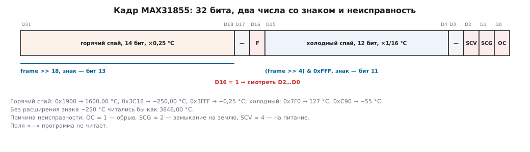
The 32-bit frame holds two signed numbers: the hot junction — 14 bits in D31…D18, in quarter degrees, and the cold junction — 12 bits in D15…D4, in sixteenths. Both are in two's complement, and the sign is extended the same way as for the HX711:
int32_t max31855_hot_q(uint32_t frame)
{
    uint32_t v = frame >> 18;
    return (v & 0x2000u) ? (int32_t)(v | 0xFFFFC000u) : (int32_t)v;
}

int32_t max31855_cold_q(uint32_t frame)
{
    uint32_t v = (frame >> 4) & 0xFFFu;
    return (v & 0x800u) ? (int32_t)(v | 0xFFFFF000u) : (int32_t)v;
}
Checking against the codes from the datasheet: 0x1900 is 1600.00 °C, 0x3C18 is −250.00 °C, 0x3FFF is −0.25 °C; cold junction 0x7F0 is 127 °C, 0xC90 is −55 °C. Without sign extension, −250 °C would turn into 3846.00 °C.
Bit D16 says that there is a fault, and D2…D0 say which one:
unsigned max31855_fault(uint32_t frame)
{
    return (frame & MAX31855_FAULT) ? (unsigned)(frame & 7u) : 0u;
}
The model with an open circuit, a short to ground and a short to the supply gives 1, 2 and 4; a healthy one gives 0. Do not take the temperature from a frame with a fault.
104.6 Correcting for non-linearity
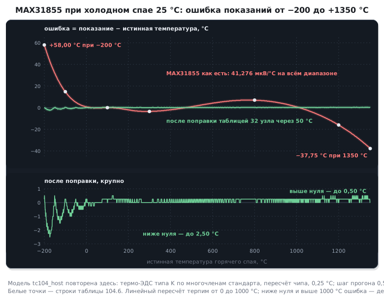
The MAX31855 converts voltage to degrees with a single coefficient: it divides it by 41.276 µV/°C and adds the cold-junction temperature. That is the exact thermoelectric voltage at 1000 °C divided by 1000 — the average slope from 0 to 1000 °C. A thermocouple is non-linear, and away from that range the error grows. The model with the cold junction at 25 °C:
| Hot junction | MAX31855 | After correction |
|---|---|---|
| −200 °C | −142.00 | −199.75 |
| −100 °C | −85.25 | −99.75 |
| 100 °C | 100.00 | 100.00 |
| 300 °C | 296.50 | 300.00 |
| 800 °C | 807.00 | 800.25 |
| 1200 °C | 1184.00 | 1200.25 |
| 1350 °C | 1312.25 | 1350.00 |
The correction works backwards: from the reading you recover the voltage the chip saw, add the cold-junction thermoelectric voltage and look up the temperature in the standard table — 32 points every 50 °C, 128 bytes:
static const int32_t K_UV[K_N] = {
    -5891, -4913, -3554, -1889,     0,  2023,  4096,  6138,
     8138, 10153, 12209, 14293, 16397, 18516, 20644, 22776,
    24905, 27025, 29129, 31213, 33275, 35313, 37326, 39314,
    41276, 43211, 45119, 46995, 48838, 50644, 52410, 54138,
};

int32_t max31855_true_q(uint32_t frame)
{
    int32_t hot = max31855_hot_q(frame), cold = max31855_cold_q(frame);
    int32_t uv = (int32_t)((int64_t)(hot * 4 - cold) * 41276 / 16000);    /* что увидел чип */
    return k_q(uv + k_uv(cold));
}
k_uv and k_q are linear interpolation between the points, in one direction and
in the other. In a sweep from −200 to +1350 °C in 0.5 °C steps, the uncorrected error
reaches 58.00 °C below zero and 37.75 °C above; after correction it is
no more than 2.50 and 0.50 °C. The correction also takes the cold junction into account: 500 °C
with the board at 25 °C is shown by the chip as 501.00, at 50 °C as 501.25,
and after correction it comes out as 500.25 and 500.00.
104.7 Pitfalls
−250 °C reads as 3846 °C. A 14-bit code without sign extension.
MAX6675 readings never change. CS is pulled low more often than once every 0.22 s — each read aborts the conversion. Read once every 250 ms.
The temperature falls as it heats up. The thermocouple wires are swapped: swapping plus and minus reverses the sign of the voltage.
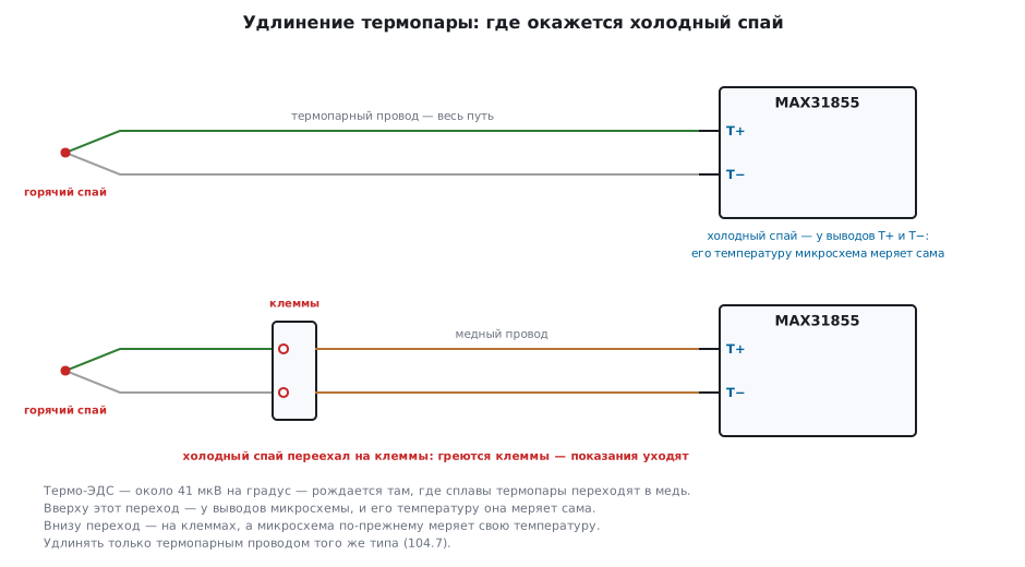
The reading drifts when the terminals warm up. The thermocouple was extended with copper wire: the cold junction moved to the terminals, while the converter measures its own temperature. Extend only with thermocouple wire of the same type.
SCG fault with an intact thermocouple. The junction touches grounded metal, and the MAX31855 sees a short to ground. You need a thermocouple with an insulated junction.
The furnace is at 1200 °C, but the display shows 1184. The MAX31855 linear conversion without correction.
The MAX31855 does not respond or gets hot. It is powered from 5 V, but it is rated for 3.0 … 3.6 V.
104.8 Summary
- A thermocouple gives a difference: hot junction minus cold. Type K is about 41 µV/°C; a 0.25 °C step is 10.3 µV.
- MAX6675: 16 bits, 0 … 1023.75 °C and only "no thermocouple"; MAX31855: 32 bits, signed, cold junction and three faults, supply 3.3 V only.
- Receive-only SPI, SCK no higher than 4.3 MHz — prescaler 32; do not pull CS low more often than once every 250 ms.
- Sign-extend the 14 and 12 bits; check the fault before the temperature.
- The MAX31855 linear conversion is off by up to 37.75 °C above zero and 58 °C below; a table of 32 points brings the error down to 0.5 and 2.5 °C.
Next: section 104а "Soldering iron on STM32: inside IronOS — a thermocouple in the tip, PID and USB Power Delivery" — the same thermocouple, but inside the tip: it is measured with the built-in ADC between heating pulses.