 Embedded HandbookApps
104б. MLX90614 IR thermometer over SMBus: contactless object temperature, PEC, emissivity and field of view
In section 96 the NTC and the DS18B20 measured the temperature of whatever they were pressed against, in 104 a thermocouple measured with its junction, in 104а a thermocouple sat right in the soldering iron tip. The MLX90614 touches nothing: it catches the thermal radiation of an object and computes the temperature from it. That is how foreheads, mugs, running motors and loaded boards are measured. Here: how it does that and why it needs to know the emissivity, how to talk to it over SMBus and check the PEC checksum, how to turn the code into degrees with integers, what the field of view is and why the background next to an object changes the reading, and how to write a new emissivity into EEPROM correctly.
Sources: RM0008 (DocID13902 Rev 17): master reception of more than two bytes,
method 2, pp. 762–763; SMBus versus I2C — 100 kHz, 10 kHz, 35 ms, p. 767; PEC —
the polynomial x⁸ + x² + x + 1 over all bytes including the addresses, p. 771.
DocID13587 Rev 17 (STM32F103x8/xB): PB6 — I2C1_SCL, PB7 — I2C1_SDA, both FT,
p. 32. How SMBus and PEC work is section 17.9 and is not repeated here. There is
no MLX90614 (Melexis) document in the project: the address, commands, EEPROM
cells, the 0.02 K step, the error flag, the range, the field of view of the
versions, supply and the EEPROM write order are taken from the manufacturer's
documentation and built into the model — per the manufacturer's documentation,
not verified. Zephyr 4.4.2 on disk has no MLX90614 driver; it has generic SMBus,
and its smbus_pec() computes PEC the same way as this section's driver. All
numbers are a run of the driver _verify/ir104c/mlx104c.c on a computer (gcc
12.2.0) against our own model of the MLX90614 as an SMBus slave and of what it
looks at, in Python 3.11; the firmware is built with armclang 6.24 for Cortex-M3.
Radiation in the model is proportional to T⁴, the field of view is a cone with
uniform sensitivity, noise and materials are assumptions: the numbers below are
about the model, not the sensor.
What the documentation calls it
Original Meaning thermopile many thermocouples in series object temperature ( Tobj)temperature of the object ambient temperature ( Ta)temperature of the sensor package emissivity (ε) share of black-body radiation the surface emits field of view (FOV) the angle radiation is collected from spot size what the sensor sees at a given distance packet error code (PEC) SMBus packet checksum repeated start a start without a stop in between clock low timeout SCL low longer than 35 ms thermal shock the sensor package is unevenly heated
104б.1 How it measures: thermopile, the Stefan–Boltzmann law and ε
Every body radiates, and the hotter it is, the more: by the Stefan–Boltzmann law
the power grows as the fourth power of absolute temperature, P ∝ ε · T⁴.
Room-temperature objects glow in the far infrared, invisible to the eye, but a
thermopile sees it. A thermopile is many thermocouples in series (thermocouple —
104.1): the hot junctions sit on a thin membrane heated by incoming radiation, the
cold ones on the package. The voltage tells the difference between what came from
the object and what the package itself radiates. That is why a second sensor sits
next to it — the package temperature Ta — and the chip computes the object
temperature Tobj from both. Per the manufacturer's documentation there is an
amplifier, an ADC and a computing unit inside, and ready words with a 0.02 K step
come out.
Emissivity ε is how much a body radiates compared with an ideal black body of the same temperature: 1 — a black body, 0 — a perfect mirror. The remainder 1 − ε the body reflects: radiation from elsewhere, reflected by the object, also reaches the sensor. The chip does not know what it looks at and computes with the configured ε. In the model the radiation of what is in the field of view is ε · T⁴ of the object plus (1 − ε) · T⁴ of the reflected, and the reading is Tobj⁴ = Ta⁴ + (radiation − Ta⁴) / configured ε.
How the reading goes wrong when ε is set wrong. In the model an object at 100 °C with ε = 0.95, room and package at 25 °C:
| Configured ε | 0.90 | 0.92 | 0.94 | 0.95 | 0.96 | 0.98 | 1.00 |
|---|---|---|---|---|---|---|---|
| reading, °C | 103.03 | 101.79 | 100.59 | 100.00 | 99.42 | 98.30 | 97.21 |
Each hundredth of ε is about 0.6 °C at 100 °C. And the farther the object is from the package temperature, the larger the error: with ε = 1.00 configured and a true 0.95 —
| Object | 0 °C | 25 °C | 40 °C | 60 °C | 100 °C | 200 °C |
|---|---|---|---|---|---|---|
| reading, °C | 1.42 | 25.00 | 39.30 | 58.50 | 97.21 | 194.94 |
At 25 °C there is no error at all: object and package are at the same temperature, and there is no difference whatever is reflected. Below the package temperature the sign of the error flips — a cold object looks warmer.
104б.2 Connecting to the F103: SMBus on top of I2C1
| Module pin | STM32F103 | Purpose |
|---|---|---|
| VIN | 3.3 V | supply: the 3 V version — only from 3.3 V |
| GND | GND | ground |
| SCL | PB6 | I2C1 clock |
| SDA | PB7 | I2C1 data; on the chip the same pin is the PWM output |
Per the manufacturer's documentation the MLX90614 comes in 5 V and 3 V versions — a letter in the version code; a bare 3 V chip is not powered from 5 V (per the manufacturer's documentation, not verified). Modules with a regulator also take 5 V, but then the pull-ups may go to 5 V: PB6 and PB7 are FT (p. 32), they will survive that.
SMBus is I2C with rules (17.9): no faster than 100 kHz and no slower than 10 kHz,
SCL low no longer than 35 ms (RM0008, p. 767). So I2C1 runs in standard mode at
100 kHz, as in 17.3: CCR = 180, TRISE = 37:
static void gpio_i2c1_init(void)
{
    RCC->APB2ENR |= RCC_APB2ENR_IOPBEN | RCC_APB2ENR_AFIOEN;
    RCC->APB1ENR |= RCC_APB1ENR_I2C1EN;
    /* PB6, PB7 — альтернативная функция, открытый сток, 2 МГц (1110): фронтам SMBus больше не нужно */
    GPIOB->CRL = (GPIOB->CRL & 0x00FFFFFFu) | 0xEE000000u;
    I2C1->CR1 = 0;                                      /* настраивать при PE = 0 */
    I2C1->CR2 = APB1_MHZ;
    I2C1->CCR = APB1_MHZ * 1000000u / (2u * 100000u);   /* стандартный режим: 36 МГц / (2 × 180) = 100 кГц */
    I2C1->TRISE = APB1_MHZ + 1u;                        /* 1000 нс × 36 МГц = 36 → 37 */
    I2C1->CR1 = I2C_CR1_PE;
}
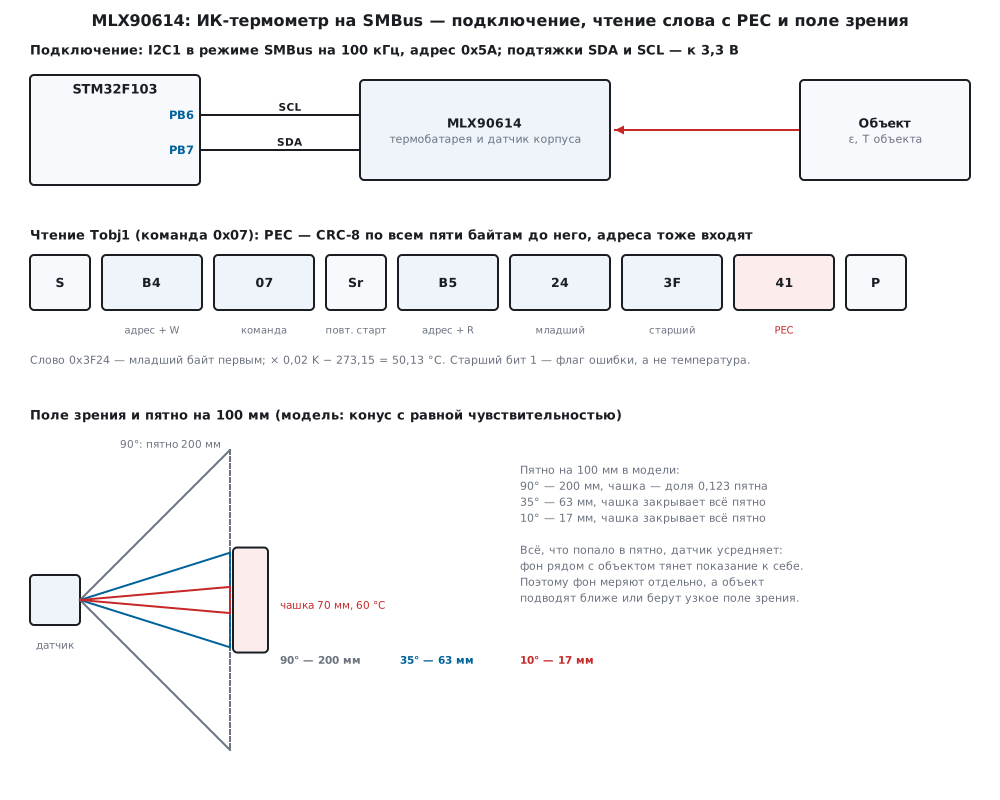
A read is a command, a repeated start and three bytes: low, high and PEC. The
F103 master receives three bytes with method 2 (pp. 762–763): wait for BTF,
clear ACK, take the first byte, BTF again, STOP, the second, then the third:
/* приём трёх байт (младший, старший, PEC) — способ 2, RM0008, с. 762–763 */
static int rx3(uint8_t *rx)
{
    int rc;
    (void)I2C1->SR2;                                    /* ADDR снят, ACK = 1 */
    if ((rc = sr1_wait(I2C_SR1_BTF)) != MLX_OK)         /* байт 1 в DR, байт 2 в сдвиговом, SCL прижат */
        return rc;
    I2C1->CR1 &= (uint16_t)~I2C_CR1_ACK;
    rx[0] = (uint8_t)I2C1->DR;                          /* пошёл приём PEC с NACK */
    if ((rc = sr1_wait(I2C_SR1_BTF)) != MLX_OK)
        return rc;
    I2C1->CR1 |= I2C_CR1_STOP;
    rx[1] = (uint8_t)I2C1->DR;
    if ((rc = sr1_wait(I2C_SR1_RXNE)) != MLX_OK)
        return rc;
    rx[2] = (uint8_t)I2C1->DR;
    I2C1->CR1 |= I2C_CR1_ACK;
    return MLX_OK;
}
The PWM output is not needed here. Per the manufacturer's documentation the SDA pin can output PWM with a duty cycle by temperature, and it is switched to SMBus by a special bus condition — SCL low longer than a given time (per the manufacturer's documentation, not verified). This section's driver works only over SMBus; the model has no PWM.
104б.3 Reading a word, PEC and conversion to degrees
The bus address per the manufacturer's documentation is 0x5A (byte 0xB4 for write and 0xB5 for read, 17.2). The command is the first byte after the address: the three top bits select the memory, the five low ones the cell:
| Command | What | What is in the word |
|---|---|---|
| 0x06 | RAM: Ta |
package temperature, 0.02 K step |
| 0x07 | RAM: Tobj1 |
object temperature, 0.02 K step; top bit — error flag |
| 0x08 | RAM: Tobj2 |
second object — only in dual-zone versions |
| 0x24 | EEPROM, cell 0x04 | emissivity: 65535 × ε |
| 0x2E | EEPROM, cell 0x0E | low byte — bus address |
All of this is per the manufacturer's documentation, not verified. The word
comes low byte first, followed by PEC. PEC is CRC-8 with polynomial 0x07 over all
bytes of the packet, the addresses included (RM0008, p. 771; code and the check on
"123456789" — 17.9). In a read these are five bytes: address with write, command,
address with read, low, high. The F103 I2C block can compute PEC itself (the
ENPEC bit, 17.9), but the driver computes it in software — the same code runs on
the test bench:
/* CRC-8 SMBus: полином x^8 + x^2 + x + 1 (0x07), старший бит первым; начальное значение — 0 */
uint8_t mlx_crc8(uint8_t crc, const uint8_t *p, uint32_t n)
{
    while (n--) {
        crc ^= *p++;
        for (int i = 0; i < 8; i++)
            crc = (crc & 0x80u) ? (uint8_t)((crc << 1) ^ 0x07u) : (uint8_t)(crc << 1);
    }
    return crc;
}
/* чтение слова: адрес + запись, команда, повторный старт, адрес + чтение, младший байт, старший, PEC;
 * PEC считается по всем пяти байтам до него — адреса тоже входят */
int mlx_read_word(mlx_t *d, uint8_t cmd, uint16_t *w)
{
    uint8_t f[5] = {(uint8_t)(d->addr << 1), cmd, (uint8_t)(d->addr << 1 | 1u), 0, 0}, rx[3];
    int rc;
    for (uint32_t i = 0; i < MLX_TRIES; i++) {
        if (i)
            d->retries++;
        if ((rc = xfer_done(d, mlx_port_xfer(d->addr, &cmd, 1, rx, 3))) != MLX_OK)
            return rc;
        f[3] = rx[0];
        f[4] = rx[1];
        if (mlx_crc8(0, f, 5) == rx[2]) {
            *w = (uint16_t)(rx[0] | rx[1] << 8);                /* младший байт первым */
            return MLX_OK;
        }
        d->pec_errors++;                                        /* помеха на линии: прочитать ещё раз */
    }
    return MLX_E_PEC;
}
In the model, reading Tobj1 with the object at 50 °C is B4 07 B5 24 3F 41: word 0x3F24,
PEC 0x41. Reading Ta is B4 06 B5 3B 3A D8. The transfer is 57 SCL clocks,
570 µs at 100 kHz; writing a word is 47 clocks, 470 µs. The driver
retries a PEC error up to three times: it is noise, and the next frame is usually
clean.
What PEC catches. In the model every tenth frame is spoiled: in the first case one bit, in the second a whole byte, in the third two bytes out of three:
| Corruption | Reads | Frames with retries | PEC mismatch | Not read in three tries | Wrong accepted | Without PEC check: spoiled / wrong accepted |
|---|---|---|---|---|---|---|
| one bit | 4000 | 4448 | 451 | 3 | 0 | 429 / 291 |
| one byte | 4000 | 4452 | 453 | 1 | 0 | 422 / 282 |
| two bytes | 20 000 | 22 227 | 2254 | 31 | 3 | 2012 / 2012 |
A single spoiled bit and even a whole byte CRC-8 always catches: not one wrong
value was accepted. Two spoiled bytes can already slip through: in the run
3 times out of 2257. Enumerating all 195 075 corruptions of
exactly two bytes out of three: PEC misses 765 — one in 255.
Without a PEC check all the spoiled data would reach the program; with one bit
spoiled there are fewer wrong values than spoiled frames — some errors landed in
the PEC itself. "Not read in three tries" is three spoiled frames in a row: the
driver honestly returns MLX_E_PEC.
Conversion to degrees. Word × 0.02 is kelvin, minus 273.15 is degrees. The F103 has no FPU, so everything is in hundredths of a degree as integers: word × 2 − 27315. The top bit of the word is not temperature but the error flag:
/* шаг 0,02 K: сотые градуса = raw × 2 − 27315 */
int32_t mlx_raw_to_c100(uint16_t raw)
{
    return (int32_t)raw * 2 - 27315;
}
/* температура в сотых °C; старший бит слова — флаг ошибки, а не температура */
int mlx_read_temp(mlx_t *d, uint8_t cmd, int32_t *c100)
{
    uint16_t w;
    int rc = mlx_read_word(d, cmd, &w);
    if (rc != MLX_OK)
        return rc;
    if (w & MLX_FLAG)
        return MLX_E_FLAG;
    *c100 = mlx_raw_to_c100(w);
    return MLX_OK;
}
| Temperature | −70 °C | −40 °C | 0 °C | 25 °C | 36.6 °C | 100 °C | 380 °C |
|---|---|---|---|---|---|---|---|
| nearest code | 0x27AE | 0x2D8A | 0x355A | 0x3A3C | 0x3C80 | 0x48E2 | 0x7F92 |
| back, °C | −69.99 | −39.99 | 0.01 | 25.01 | 36.61 | 100.01 | 380.01 |
273.15 / 0.02 = 13 657.5 — half a step: whole degrees fall between codes, and
the way back gives 0.01 °C more. Ta in the model at 25 °C is 24.99 °C: the model
rounded the half step the other way. The largest word without the flag, 0x7FFF, is
382.19 °C; the object range per the manufacturer's documentation is −70…380 °C
(not verified). In the model an object at 500 °C and at −100 °C is out of range:
the word is 0x8000, the driver returns MLX_E_FLAG, −4. Without the flag check
it would be 382.21 °C.
104б.4 Field of view and spot: what gets into the measurement
The sensor collects radiation from a cone — the field of view. Per the manufacturer's documentation it differs between versions: 90°, 35°, 10° and narrower — narrow ones use a lens or a long tube (not verified). At distance d the spot is a circle of diameter 2 · d · tan(FOV / 2):
| Field of view | 10 mm | 50 mm | 100 mm | 300 mm | 1000 mm |
|---|---|---|---|---|---|
| 90° | 20 mm | 100 mm | 200 mm | 600 mm | 2000 mm |
| 35° | 6 mm | 32 mm | 63 mm | 189 mm | 631 mm |
| 10° | 2 mm | 9 mm | 17 mm | 52 mm | 175 mm |
The sensor averages everything in the spot by radiation. If the object is smaller than the spot, the rest is background. In the model a 70 mm mug at 60 °C, ε = 0.95 (also 0.95 configured), wall and air at 25 °C:
| Distance | 20 mm | 50 mm | 100 mm | 200 mm | 500 mm |
|---|---|---|---|---|---|
| 90°, reading | 60.00 | 43.60 | 29.98 | 26.26 | 25.20 |
| 90°, corrected | 60.01 | 60.01 | 59.91 | 59.47 | 58.85 |
| 35°, reading | 60.00 | 60.00 | 60.00 | 37.08 | 27.03 |
| 35°, corrected | 60.01 | 60.01 | 60.01 | 60.01 | 60.01 |
| 10°, reading | 60.00 | 60.00 | 60.00 | 60.00 | 48.69 |
| 10°, corrected | 60.01 | 60.01 | 60.01 | 60.01 | 60.01 |
With 90° already at 100 mm the mug is only 0.123 of the spot, and the reading is 29.98 °C instead of 60. With 10° the mug covers the whole spot up to 200 mm. Hence the rule: the object must be larger than the spot, preferably twice — bring the sensor closer or take a narrow field of view.
Why measure the background nearby. Knowing the share w of the spot the object
takes, and the background, the reading can be split back: T⁴ = (Tm⁴ − (1 − w) ·
Tbg⁴) / w. The same formula with Tbg = Ta and w = ε is the emissivity
correction. In code it is one function, all in word units and in 64 bits:
/* показание — смесь двух излучений с долями w и 1 − w (в тысячных): T⁴ = (Tm⁴ − (1 − w)·To⁴) / w.
 * other = Ta, w = ε — поправка на излучательную способность; other = фон, w = доля пятна — на неполное пятно.
 * Всё в единицах слова, 0,02 K; 32767⁴ ≈ 1,15·10¹⁸ — помещается в 64 бита */
uint16_t mlx_unmix(uint16_t meas, uint16_t other, uint32_t w1000)
{
    uint64_t m4, o4, t, x, q, r;
    if (w1000 < 1u || w1000 > 1000u)
        return 0u;
    m4 = pow4(meas & 0x7FFFu);
    o4 = pow4(other & 0x7FFFu);
    t = o4 / 1000u * (1000u - w1000) + o4 % 1000u * (1000u - w1000) / 1000u;
    if (m4 <= t)
        return 0u;
    x = m4 - t;
    if (x / w1000 > UINT64_MAX / 1000u)
        return 0x7FFFu;
    q = x / w1000 * 1000u + x % w1000 * 1000u / w1000;
    r = isqrt64(isqrt64(q));
    if (r >= 0x7FFFu)
        return 0x7FFFu;
    if (pow4(r + 1u) - q < q - pow4(r))
        r++;                                                    /* к ближайшему */
    return (uint16_t)r;
}
The background is not guessed but measured with the same sensor, turned to what surrounds the object. The "corrected" rows above were obtained that way: the background is 25.01 °C, and the correction returns 60 °C to within noise. The smaller the share of the spot, the more the noise grows: at 500 mm and 90° — 58.85 °C. And if behind the mug there is a 45 °C radiator, not a wall? The reading is 47.78 °C, the background nearby is 45.98 °C. Correction with the measured background gives 59.83 °C, and with the package temperature instead of the background — 142.75 °C. The background cannot be replaced by room temperature.
104б.5 Emissivity: materials and writing to EEPROM
Skin, water, paint and wood have high ε, shiny metal a tiny one: it is almost a mirror and shows what is reflected in it. In the model the ε of materials are typical values, a model assumption, not a table from a document. A 60 °C object fills the spot, 25 °C around, the mean of 16 readings:
| Material | ε in the model | At ε = 1.00 | ε written to EEPROM | Correction in software |
|---|---|---|---|---|
| skin | 0.98 | 59.40 | 60.00 | 60.01 |
| water | 0.96 | 58.80 | 60.00 | 60.01 |
| matte black paint | 0.95 | 58.50 | 60.00 | 60.01 |
| wood | 0.90 | 56.98 | 60.00 | 60.01 |
| oxidised steel | 0.80 | 53.86 | 60.00 | 60.01 |
| stainless steel | 0.15 | 31.06 | 60.00 | 60.09 |
| polished aluminium | 0.05 | 27.06 | 60.00 | 60.27 |
For skin and water ε = 1 barely lies — about a degree at 60 °C. Oxidised steel
is already six degrees low, polished aluminium shows almost room temperature. The
right ε in EEPROM brings back 60 °C for all, just like the mlx_unmix correction
in software; for aluminium it is already noticeably noisy, 60.27 °C: dividing
by 0.05 multiplies noise twentyfold. In the model the noise is added to the final
reading, so with ε written it does not grow; in the sensor it grows too at small ε
(not verified). But for a metal with small ε the correction in the model works
only while the room is what is reflected: if a hot 80 °C lamp faces an aluminium
part (ε = 0.05), the reading with the right ε is 357.02 °C. Such surfaces are
painted matte or covered with black tape of known ε before measuring.
Writing ε to EEPROM. The code is round(65535 × ε): 1.00 → 0xFFFF, 0.98 → 0xFAE0, 0.95 → 0xF332, 0.90 → 0xE666, 0.05 → 0x0CCD (per the manufacturer's documentation, not verified). Per the manufacturer's documentation the cell is first erased — 0 is written — then one waits, writes the new value and waits again. EEPROM write endurance is limited, so the driver first reads the cell and writes nothing if the value is the same:
/* запись ячейки EEPROM: то же значение — не трогать; иначе стереть (записать 0), выждать, записать, выждать,
 * прочитать обратно */
int mlx_ee_write(mlx_t *d, uint8_t cmd, uint16_t w)
{
    uint16_t now;
    int rc;
    if ((rc = mlx_read_word(d, cmd, &now)) != MLX_OK)
        return rc;
    if (now == w)
        return MLX_OK;                                          /* ресурс записи ограничен: лишних записей нет */
    if ((rc = mlx_write_word(d, cmd, 0)) != MLX_OK)
        return rc;
    mlx_port_delay_us(MLX_EE_WAIT_US);
    if ((rc = mlx_write_word(d, cmd, w)) != MLX_OK)
        return rc;
    mlx_port_delay_us(MLX_EE_WAIT_US);
    if ((rc = mlx_read_word(d, cmd, &now)) != MLX_OK)
        return rc;
    return now == w ? MLX_OK : MLX_E_VERIFY;
}
In the model changing ε from 1.00 to 0.95 is 4 transfers: read 24, write 24 00 00 28, write 24 32 F3 2C, read 24;
2080 µs of bus and 22 080 µs including the 10 ms pauses. A repeated call
with the same ε is 1 transfer, 570 µs, no write; after 100 power-ups,
on each of which the firmware sets 0.95 again, the cell still has 2 writes.
That is why the firmware writes ε only on change. In the model the new ε applies
at once; when it takes effect in the chip is per the manufacturer's documentation,
not verified. The address is changed the same way — the low byte of cell 0x0E, the
high byte is not ours and is kept: in the model the cell became 0xBE5B, and
the old address answers until power is removed, after that only the new one.
104б.6 Thermal shock and averaging
The thermopile measures the difference between the membrane and the cold
junctions on the package, and the computing unit substitutes Ta for the
junctions — the package temperature at another spot. While the package is evenly
warm, this is the same thing. If the sensor was brought in from the cold, a
regulator heats up next to it or a lamp shines on the package, the package is
unevenly warm and the reading drifts — that is thermal shock. This behaviour is not
modelled in detail here. The model has only a skew: the cold junctions are warmer
than the Ta sensor, object at 60 °C:
| Skew | 0 K | 0.5 K | 1 K | 2 K |
|---|---|---|---|---|
| reading, °C | 60.00 | 59.64 | 59.28 | 58.54 |
A 1 K skew gives about 0.72 °C of error. The remedies are mechanical: keep the sensor away from warm parts, let it warm up after moving, do not touch the package by hand.
Averaging does not help against the skew — it is the same in all readings — but it helps against noise. In the model the noise of one reading is 0.1 K; readings are separated by a 100 ms pause because the chip does not update its result instantly (the period is per the manufacturer's documentation, not verified). 200 means:
/* среднее n показаний с паузой gap_us между ними, округление к ближайшему */
int mlx_avg(mlx_t *d, uint8_t cmd, uint32_t n, uint32_t gap_us, int32_t *c100)
{
    int32_t s = 0, t;
    int rc;
    if (!n)
        return MLX_E_BUS;
    for (uint32_t i = 0; i < n; i++) {
        if (i)
            mlx_port_delay_us(gap_us);
        if ((rc = mlx_read_temp(d, cmd, &t)) != MLX_OK)
            return rc;
        s += t;
    }
    *c100 = s >= 0 ? (s + (int32_t)(n / 2u)) / (int32_t)n : -((-s + (int32_t)(n / 2u)) / (int32_t)n);
    return MLX_OK;
}
| Readings in the mean | 1 | 4 | 16 |
|---|---|---|---|
| spread of the mean, K | 0.099 | 0.054 | 0.028 |
| time, ms | 0.6 | 302.3 | 1509.1 |
Four times more readings — almost half the spread, and four times the time.
104б.7 Pitfalls
Garbage or NACK although the address is right: SCL was held too long. An SMBus transfer must not be paused for long: SCL low for longer than 35 ms (RM0008, p. 767), and the slave resets the transfer. In the model a 20 ms pause in the middle of a read gives code 0, 40 ms — −1 (NACK). An interrupt with a long handler in the middle of a transfer is the same pause.
PEC never matches: no repeated start. The command was written and STOP
issued, then three bytes were read in a separate transfer. In the model the
command is forgotten after STOP, and FF FF FF arrived — PEC 0xFF did not
match the expected 0x22 (what the chip does, not verified). Read only with
a repeated start (17.2).
PEC always fails on a correct transfer. PEC is computed over all bytes: address with write, command, address with read, data. Forget the addresses or use the address without the read bit — the sum differs. This is visible at once: not a single read passes.
Strange readings after writing ε. It was written without erasing. In the model a write without zero gives "old OR new" (that is how the model behaves; what the chip does — per the manufacturer's documentation it must be erased, not verified): from 0xF332 (0.95) to 0xE666 (0.90) the cell holds 0xF776 — ε = 0.9667, and a 100 °C object reads as 96.13 °C. With erasing — 100.00 °C. Without a pause the second write gets NACK (code −1), and the cell stays erased, 0x0000, — ε = 0. Check the return code and read the cell back.
Through glass you measure the glass. Ordinary glass is opaque in the far IR (in the model completely, with ε = 0.92): a 60 °C object behind a room-temperature glass window reads as 25.01 °C. A window in front of the sensor is made of a material transparent in its band, or one measures without a window.
Shiny is cold. A metal with small ε at ε = 1 configured shows almost room temperature (104б.5), and with the right ε — what is reflected in it. Tape or paint of known ε.
The reading is lower than reality. The object is smaller than the spot (104б.4), or the sensor looks past it. Check the spot at your distance.
A 3 V version on 5 V. Per the manufacturer's documentation the 3 and 5 V versions differ; a bare 3 V chip can burn on 5 V (not verified). On a module look at the regulator and pull-ups.
104б.8 Summary
- The MLX90614 computes the object temperature from radiation: the thermopile
measures the difference with the package,
Tais the package; per the manufacturer's documentation the address is 0x5A,Ta— 0x06,Tobj1— 0x07, ε — 0x24, address — 0x2E, step 0.02 K. - SMBus is I2C1 at 100 kHz (
CCR= 180,TRISE= 37), reads with a repeated start, SCL low no longer than 35 ms. - PEC is CRC-8 with polynomial 0x07 over five bytes including the addresses; in the model it catches any spoiled bit and byte, and of 2257 frames with two spoiled bytes it let 3 through.
- Degrees as integers: word × 2 − 27315 hundredths; the top bit is the error flag.
- A wrong ε gives an error growing with the difference from the package: in the model with a true ε of 0.95 and 1.00 configured — −2.79 °C at 100 °C and −5.06 °C at 200 °C.
- The spot is 2 · d · tan(FOV / 2): at 90° and 100 mm a 70 mm mug reads 29.98 °C instead of 60; measure the background next to the object and subtract it.
- EEPROM: read, if different erase (0), wait, write, wait, read back; do not rewrite the same value.
Full sources
mlx104c.h — commands, cells, error codes, port and functions of the MLX90614 driver.
/* mlx104c.h — раздел 104б: драйвер ИК-термометра MLX90614 по SMBus без регистров микроконтроллера. Драйвер говорит
 * с микросхемой только через функции порта (mlx_port_*): в прошивке fw104c.c их делает I2C1 STM32F103, в стенде
 * host104c.c — модель model104c.py. Адрес, команды RAM и EEPROM, ячейки, шаг 0,02 K и флаг ошибки в старшем бите —
 * по документации производителя (Melexis); документа в проекте нет, с микросхемой не сверено. PEC — CRC-8 SMBus
 * с полиномом 0x07 по всем байтам посылки, включая адреса (RM0008, с. 771; smbus_pec() в Zephyr 4.4.2). */
#ifndef MLX104C_H
#define MLX104C_H
#include <stdint.h>

/* ── команды: 000x xxxx — RAM, 001x xxxx — EEPROM ─────────────────────── */
#define MLX_RAM_TA        0x06u         /* температура корпуса датчика */
#define MLX_RAM_TOBJ1     0x07u         /* температура объекта, зона 1 */
#define MLX_RAM_TOBJ2     0x08u         /* зона 2 — только у двухзонных версий */
#define MLX_EE            0x20u         /* 0x20 | ячейка EEPROM */
#define MLX_EE_EMIS       0x24u         /* ячейка 0x04: излучательная способность, 65535 × ε */
#define MLX_EE_ADDR       0x2Eu         /* ячейка 0x0E: младший байт — адрес на шине */

#define MLX_ADDR          0x5Au         /* семибитный: 0xB4 запись, 0xB5 чтение */
#define MLX_FLAG          0x8000u       /* старший бит слова температуры: ошибка, не температура */
#define MLX_EE_WAIT_US    10000u        /* пауза после записи ячейки EEPROM */
#define MLX_TRIES         3u            /* повторов чтения, если PEC не сошёлся */

enum { MLX_OK = 0, MLX_E_NACK = -1, MLX_E_BUS = -2, MLX_E_PEC = -3, MLX_E_FLAG = -4, MLX_E_VERIFY = -5 };

typedef struct {
    uint8_t addr;
    uint32_t xfers, errors, pec_errors, retries, ee_writes;
} mlx_t;

/* ── порт: в прошивке — I2C1, в стенде — строки к модели ──────────────── */
/* ntx байт записи, затем (если nrx) повторный старт и nrx байт чтения; 0, MLX_E_NACK или MLX_E_BUS */
int mlx_port_xfer(uint8_t addr7, const uint8_t *tx, uint32_t ntx, uint8_t *rx, uint32_t nrx);
void mlx_port_delay_us(uint32_t us);

/* ── драйвер ──────────────────────────────────────────────────────────── */
uint8_t mlx_crc8(uint8_t crc, const uint8_t *p, uint32_t n);
int mlx_read_word(mlx_t *d, uint8_t cmd, uint16_t *w);
int mlx_write_word(mlx_t *d, uint8_t cmd, uint16_t w);
int32_t mlx_raw_to_c100(uint16_t raw);
uint16_t mlx_c100_to_raw(int32_t c100);
int mlx_read_temp(mlx_t *d, uint8_t cmd, int32_t *c100);
int mlx_avg(mlx_t *d, uint8_t cmd, uint32_t n, uint32_t gap_us, int32_t *c100);
int mlx_ee_write(mlx_t *d, uint8_t cmd, uint16_t w);
uint16_t mlx_emis_code(uint32_t e1000);
int mlx_set_emissivity(mlx_t *d, uint32_t e1000);
int mlx_set_addr(mlx_t *d, uint8_t new7);
uint16_t mlx_unmix(uint16_t meas, uint16_t other, uint32_t w1000);

#endif
mlx104c.c — driver: CRC-8, word read and write with PEC, degrees, EEPROM, emissivity and background correction.
/* mlx104c.c — раздел 104б: драйвер MLX90614 по SMBus. Один и тот же файл собирается в прошивку (armclang,
 * Cortex-M3) и в стенд на компьютере (gcc): микроконтроллера он не знает, только порт mlx_port_*. */
#include "mlx104c.h"

static int xfer_done(mlx_t *d, int rc)
{
    d->xfers++;
    if (rc)
        d->errors++;
    return rc;
}

/* CRC-8 SMBus: полином x^8 + x^2 + x + 1 (0x07), старший бит первым; начальное значение — 0 */
uint8_t mlx_crc8(uint8_t crc, const uint8_t *p, uint32_t n)
{
    while (n--) {
        crc ^= *p++;
        for (int i = 0; i < 8; i++)
            crc = (crc & 0x80u) ? (uint8_t)((crc << 1) ^ 0x07u) : (uint8_t)(crc << 1);
    }
    return crc;
}

/* чтение слова: адрес + запись, команда, повторный старт, адрес + чтение, младший байт, старший, PEC;
 * PEC считается по всем пяти байтам до него — адреса тоже входят */
int mlx_read_word(mlx_t *d, uint8_t cmd, uint16_t *w)
{
    uint8_t f[5] = {(uint8_t)(d->addr << 1), cmd, (uint8_t)(d->addr << 1 | 1u), 0, 0}, rx[3];
    int rc;
    for (uint32_t i = 0; i < MLX_TRIES; i++) {
        if (i)
            d->retries++;
        if ((rc = xfer_done(d, mlx_port_xfer(d->addr, &cmd, 1, rx, 3))) != MLX_OK)
            return rc;
        f[3] = rx[0];
        f[4] = rx[1];
        if (mlx_crc8(0, f, 5) == rx[2]) {
            *w = (uint16_t)(rx[0] | rx[1] << 8);                /* младший байт первым */
            return MLX_OK;
        }
        d->pec_errors++;                                        /* помеха на линии: прочитать ещё раз */
    }
    return MLX_E_PEC;
}

/* запись слова: адрес + запись, команда, младший байт, старший, PEC по четырём байтам до него */
int mlx_write_word(mlx_t *d, uint8_t cmd, uint16_t w)
{
    uint8_t f[5] = {(uint8_t)(d->addr << 1), cmd, (uint8_t)w, (uint8_t)(w >> 8), 0};
    f[4] = mlx_crc8(0, f, 4);
    if ((cmd & 0xE0u) == MLX_EE)
        d->ee_writes++;
    return xfer_done(d, mlx_port_xfer(d->addr, f + 1, 4, 0, 0));
}

/* шаг 0,02 K: сотые градуса = raw × 2 − 27315 */
int32_t mlx_raw_to_c100(uint16_t raw)
{
    return (int32_t)raw * 2 - 27315;
}

uint16_t mlx_c100_to_raw(int32_t c100)
{
    int32_t k2 = c100 + 27315;                                  /* сотые кельвина */
    return k2 <= 0 ? 0u : (uint16_t)((k2 + 1) / 2);
}

/* температура в сотых °C; старший бит слова — флаг ошибки, а не температура */
int mlx_read_temp(mlx_t *d, uint8_t cmd, int32_t *c100)
{
    uint16_t w;
    int rc = mlx_read_word(d, cmd, &w);
    if (rc != MLX_OK)
        return rc;
    if (w & MLX_FLAG)
        return MLX_E_FLAG;
    *c100 = mlx_raw_to_c100(w);
    return MLX_OK;
}

/* среднее n показаний с паузой gap_us между ними, округление к ближайшему */
int mlx_avg(mlx_t *d, uint8_t cmd, uint32_t n, uint32_t gap_us, int32_t *c100)
{
    int32_t s = 0, t;
    int rc;
    if (!n)
        return MLX_E_BUS;
    for (uint32_t i = 0; i < n; i++) {
        if (i)
            mlx_port_delay_us(gap_us);
        if ((rc = mlx_read_temp(d, cmd, &t)) != MLX_OK)
            return rc;
        s += t;
    }
    *c100 = s >= 0 ? (s + (int32_t)(n / 2u)) / (int32_t)n : -((-s + (int32_t)(n / 2u)) / (int32_t)n);
    return MLX_OK;
}

/* запись ячейки EEPROM: то же значение — не трогать; иначе стереть (записать 0), выждать, записать, выждать,
 * прочитать обратно */
int mlx_ee_write(mlx_t *d, uint8_t cmd, uint16_t w)
{
    uint16_t now;
    int rc;
    if ((rc = mlx_read_word(d, cmd, &now)) != MLX_OK)
        return rc;
    if (now == w)
        return MLX_OK;                                          /* ресурс записи ограничен: лишних записей нет */
    if ((rc = mlx_write_word(d, cmd, 0)) != MLX_OK)
        return rc;
    mlx_port_delay_us(MLX_EE_WAIT_US);
    if ((rc = mlx_write_word(d, cmd, w)) != MLX_OK)
        return rc;
    mlx_port_delay_us(MLX_EE_WAIT_US);
    if ((rc = mlx_read_word(d, cmd, &now)) != MLX_OK)
        return rc;
    return now == w ? MLX_OK : MLX_E_VERIFY;
}

/* код излучательной способности: round(65535 × ε), ε — в тысячных, 1…1000 */
uint16_t mlx_emis_code(uint32_t e1000)
{
    if (e1000 < 1u)
        e1000 = 1u;
    if (e1000 > 1000u)
        e1000 = 1000u;
    return (uint16_t)((65535u * e1000 + 500u) / 1000u);
}

int mlx_set_emissivity(mlx_t *d, uint32_t e1000)
{
    return mlx_ee_write(d, MLX_EE_EMIS, mlx_emis_code(e1000));
}

/* новый адрес: младший байт ячейки 0x0E, старший — не наш, его сохранить; заработает после выключения питания */
int mlx_set_addr(mlx_t *d, uint8_t new7)
{
    uint16_t now;
    int rc;
    if (new7 < 1u || new7 > 0x7Fu)
        return MLX_E_BUS;
    if ((rc = mlx_read_word(d, MLX_EE_ADDR, &now)) != MLX_OK)
        return rc;
    return mlx_ee_write(d, MLX_EE_ADDR, (uint16_t)((now & 0xFF00u) | new7));
}

static uint64_t isqrt64(uint64_t v)
{
    uint64_t r = 0, b = 1ull << 62;
    while (b > v)
        b >>= 2;
    while (b) {
        if (v >= r + b) {
            v -= r + b;
            r = (r >> 1) + b;
        } else {
            r >>= 1;
        }
        b >>= 2;
    }
    return r;
}

static uint64_t pow4(uint64_t x)
{
    return x * x * x * x;
}

/* показание — смесь двух излучений с долями w и 1 − w (в тысячных): T⁴ = (Tm⁴ − (1 − w)·To⁴) / w.
 * other = Ta, w = ε — поправка на излучательную способность; other = фон, w = доля пятна — на неполное пятно.
 * Всё в единицах слова, 0,02 K; 32767⁴ ≈ 1,15·10¹⁸ — помещается в 64 бита */
uint16_t mlx_unmix(uint16_t meas, uint16_t other, uint32_t w1000)
{
    uint64_t m4, o4, t, x, q, r;
    if (w1000 < 1u || w1000 > 1000u)
        return 0u;
    m4 = pow4(meas & 0x7FFFu);
    o4 = pow4(other & 0x7FFFu);
    t = o4 / 1000u * (1000u - w1000) + o4 % 1000u * (1000u - w1000) / 1000u;
    if (m4 <= t)
        return 0u;
    x = m4 - t;
    if (x / w1000 > UINT64_MAX / 1000u)
        return 0x7FFFu;
    q = x / w1000 * 1000u + x % w1000 * 1000u / w1000;
    r = isqrt64(isqrt64(q));
    if (r >= 0x7FFFu)
        return 0x7FFFu;
    if (pow4(r + 1u) - q < q - pow4(r))
        r++;                                                    /* к ближайшему */
    return (uint16_t)r;
}
fw104c.c — F103 firmware: I2C1 at 100 kHz, three-byte reception, averaging, emissivity to EEPROM only on change.
/* fw104c.c — раздел 104б: MLX90614 на STM32F103 (BluePill), 72 МГц, APB1 = 36 МГц.
 * I2C1: PB6 — SCL, PB7 — SDA (открытый сток, 100 кГц — верх SMBus). Цикл: четыре показания объекта с паузой
 * 100 мс — среднее, температура корпуса, при заданной доле пятна — поправка на фон. Настройки — через
 * отладчик: emis1000 — излучательная способность в тысячных (пишется в EEPROM, только если изменилась),
 * fill1000 и bg_c100 — доля пятна, занятая объектом, и температура фона рядом с ним. Тактирование до 72 МГц —
 * как в разделе 6. */
#include "stm32f10x.h"
#include "mlx104c.h"

#define CPU_HZ          72000000u
#define APB1_MHZ        36u
#define I2C_TIMEOUT_US  2000u           /* байт на 100 кГц — 90 мкс; весь обмен много короче 35 мс */
#define AVG_N           4u
#define AVG_GAP_US      100000u

static mlx_t dev = {.addr = MLX_ADDR};
volatile uint32_t emis1000 = 1000u, fill1000 = 1000u, bus_errors, flag_errors;
volatile int32_t t_obj_c100, t_amb_c100, bg_c100 = 2500, t_fixed_c100;
static uint32_t emis_now;                   /* 0: при запуске сверить с ячейкой — запись, только если другое */

static int expired(uint32_t t0, uint32_t us)
{
    return DWT->CYCCNT - t0 >= us * (CPU_HZ / 1000000u);
}

void mlx_port_delay_us(uint32_t us)
{
    uint32_t t0 = DWT->CYCCNT;
    while (!expired(t0, us)) {
    }
}

static void gpio_i2c1_init(void)
{
    RCC->APB2ENR |= RCC_APB2ENR_IOPBEN | RCC_APB2ENR_AFIOEN;
    RCC->APB1ENR |= RCC_APB1ENR_I2C1EN;
    /* PB6, PB7 — альтернативная функция, открытый сток, 2 МГц (1110): фронтам SMBus больше не нужно */
    GPIOB->CRL = (GPIOB->CRL & 0x00FFFFFFu) | 0xEE000000u;
    I2C1->CR1 = 0;                                      /* настраивать при PE = 0 */
    I2C1->CR2 = APB1_MHZ;
    I2C1->CCR = APB1_MHZ * 1000000u / (2u * 100000u);   /* стандартный режим: 36 МГц / (2 × 180) = 100 кГц */
    I2C1->TRISE = APB1_MHZ + 1u;                        /* 1000 нс × 36 МГц = 36 → 37 */
    I2C1->CR1 = I2C_CR1_PE;
}

static int sr1_wait(uint16_t mask)
{
    uint32_t t0 = DWT->CYCCNT;
    while (!(I2C1->SR1 & mask)) {
        if (I2C1->SR1 & I2C_SR1_AF)
            return MLX_E_NACK;                          /* адрес или байт не подтверждён */
        if (expired(t0, I2C_TIMEOUT_US))
            return MLX_E_BUS;
    }
    return MLX_OK;
}

static int fail(int rc)
{
    I2C1->CR1 |= I2C_CR1_STOP;
    I2C1->SR1 = (uint16_t)~I2C_SR1_AF;                  /* AF снимается записью нуля */
    I2C1->CR1 |= I2C_CR1_ACK;
    return rc;
}

/* приём трёх байт (младший, старший, PEC) — способ 2, RM0008, с. 762–763 */
static int rx3(uint8_t *rx)
{
    int rc;
    (void)I2C1->SR2;                                    /* ADDR снят, ACK = 1 */
    if ((rc = sr1_wait(I2C_SR1_BTF)) != MLX_OK)         /* байт 1 в DR, байт 2 в сдвиговом, SCL прижат */
        return rc;
    I2C1->CR1 &= (uint16_t)~I2C_CR1_ACK;
    rx[0] = (uint8_t)I2C1->DR;                          /* пошёл приём PEC с NACK */
    if ((rc = sr1_wait(I2C_SR1_BTF)) != MLX_OK)
        return rc;
    I2C1->CR1 |= I2C_CR1_STOP;
    rx[1] = (uint8_t)I2C1->DR;
    if ((rc = sr1_wait(I2C_SR1_RXNE)) != MLX_OK)
        return rc;
    rx[2] = (uint8_t)I2C1->DR;
    I2C1->CR1 |= I2C_CR1_ACK;
    return MLX_OK;
}

int mlx_port_xfer(uint8_t addr7, const uint8_t *tx, uint32_t ntx, uint8_t *rx, uint32_t nrx)
{
    int rc;
    uint32_t t0 = DWT->CYCCNT;
    if ((nrx != 0u && nrx != 3u) || ntx == 0u)
        return MLX_E_BUS;                               /* драйвер пишет команду и читает слово с PEC — 3 байта */
    while (I2C1->SR2 & I2C_SR2_BUSY) {                  /* SDA держит ведомый — раздел 17.6 */
        if (expired(t0, I2C_TIMEOUT_US))
            return MLX_E_BUS;
    }
    I2C1->CR1 |= I2C_CR1_ACK;
    I2C1->CR1 |= I2C_CR1_START;
    if ((rc = sr1_wait(I2C_SR1_SB)) != MLX_OK)
        return fail(rc);
    I2C1->DR = (uint8_t)(addr7 << 1);
    if ((rc = sr1_wait(I2C_SR1_ADDR)) != MLX_OK)
        return fail(rc);
    (void)I2C1->SR2;
    for (uint32_t i = 0; i < ntx; i++) {
        if ((rc = sr1_wait(I2C_SR1_TXE)) != MLX_OK)
            return fail(rc);
        I2C1->DR = tx[i];
    }
    if ((rc = sr1_wait(I2C_SR1_BTF)) != MLX_OK)
        return fail(rc);
    if (!nrx) {
        I2C1->CR1 |= I2C_CR1_STOP;
        return MLX_OK;
    }
    I2C1->CR1 |= I2C_CR1_START;                         /* повторный старт: без него команда потеряна */
    if ((rc = sr1_wait(I2C_SR1_SB)) != MLX_OK)
        return fail(rc);
    I2C1->DR = (uint8_t)(addr7 << 1 | 1u);
    if ((rc = sr1_wait(I2C_SR1_ADDR)) != MLX_OK)
        return fail(rc);
    if ((rc = rx3(rx)) != MLX_OK)
        return fail(rc);
    return MLX_OK;
}

static void count(int rc)
{
    if (rc == MLX_E_FLAG)
        flag_errors++;
    else if (rc != MLX_OK)
        bus_errors++;
}

int main(void)
{
    int32_t t;
    int rc;
    CoreDebug->DEMCR |= CoreDebug_DEMCR_TRCENA_Msk;
    DWT->CYCCNT = 0;
    DWT->CTRL |= DWT_CTRL_CYCCNTENA_Msk;
    gpio_i2c1_init();
    while (mlx_read_temp(&dev, MLX_RAM_TA, &t) != MLX_OK)
        mlx_port_delay_us(100000u);                     /* нет ответа: провод, адрес, питание, режим ШИМ */
    for (;;) {
        if (emis1000 != emis_now) {                     /* EEPROM — только при изменении */
            count(rc = mlx_set_emissivity(&dev, emis1000));
            if (rc == MLX_OK)
                emis_now = emis1000;
        }
        if ((rc = mlx_read_temp(&dev, MLX_RAM_TA, &t)) == MLX_OK)
            t_amb_c100 = t;
        count(rc);
        if ((rc = mlx_avg(&dev, MLX_RAM_TOBJ1, AVG_N, AVG_GAP_US, &t)) != MLX_OK) {
            count(rc);
            continue;
        }
        t_obj_c100 = t;
        t_fixed_c100 = fill1000 >= 1000u ? t
                                         : mlx_raw_to_c100(mlx_unmix(mlx_c100_to_raw(t), mlx_c100_to_raw(bg_c100), fill1000));
        mlx_port_delay_us(AVG_GAP_US);
    }
}
Next: part XII "Networks and DevOps for the engineer", section 105 "Networking from the bottom up: Ethernet, MAC, IP, subnets, ARP" — what happens to a frame from the connector to the IP address.