 Embedded HandbookApps
22ж. IR remote and the NEC protocol: VS1838/TSOP receiver, timer capture, interrupt-driven decoder, repeat and noise
In sections 22д and 22е the microcontroller produced output: characters on a screen, digits and dots on displays. Here it is input, and the cheapest wireless kind: a TV remote and a three-pin IR receiver. The receiver strips the carrier itself and puts bursts and pauses on its pin; the firmware only has to measure them with a timer and tell a zero from a one without losing the frame to edge jitter and lamp light. Mini-project 198о does the same on the STM32G474 with its ready IRTIM block; here is the basis on the STM32F103: what comes out of the receiver, the NEC frame, TIM2 capture in PWM input mode, the decoder state machine in the interrupt, holding a key, noise and, briefly, transmission.
Sources: RM0008 (DocID13902 Rev 17): the frequency of the timers on APB1
is doubled, p. 93; capture, p. 383; PWM input, p. 384; the slave reset
mode, p. 394; the CKD bit, p. 403; the URS bit, p. 404; the IC1F
filter, p. 414; CC1P and the reserved bits 3:2 of CCER, p. 417.
DocID13587 Rev 17 (STM32F103x8/xB): PA0 is TIM2_CH1_ETR without 5 V
tolerance, PA6 is TIM3_CH1, p. 29. The project has no documents on IR
receivers or on the NEC protocol: the NEC timings are the well-known ones,
the same as in section 198о and in the lab bench. All numbers below come
from a run of the decoder _verify/irnec22h/irnec22h.c on a computer (gcc
12.2.0) with our own model of the remote, the receiver and TIM2 in Python
3.11; the firmware is built by armclang 6.24 for the Cortex-M3.
What it is called in the documentation
Original Meaning carrier carrier demodulator demodulator: removes the carrier, leaves the envelope mark, burst / space carrier burst / pause leader frame leader repeat code repeat code extended NEC extended NEC, 16-bit address input capture capture PWM input mode PWM input mode slave mode: reset mode slave mode: counter reset update request source (URS) what raises the update flag input filter, sampling frequency input filter, sampling frequency duty cycle duty cycle
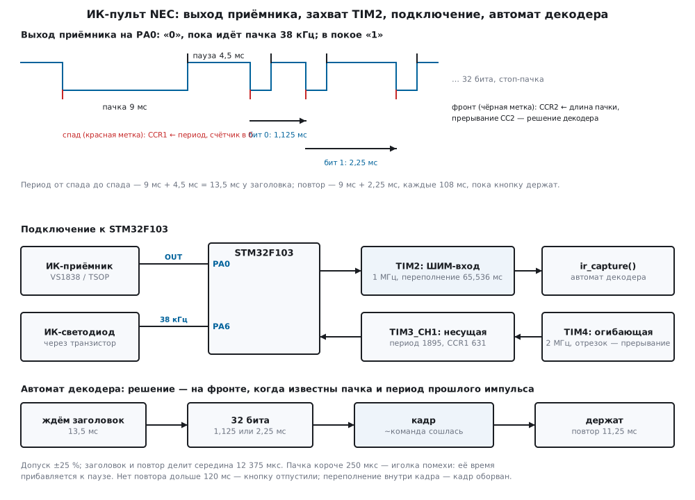
22ж.1 What the IR receiver gives
A remote does not shine continuously but in bursts of a carrier, 38 kHz for NEC. Inside a three-pin receiver (the VS1838, the TSOP series and similar ones) sit a photodiode, an amplifier, a filter tuned to the carrier and a demodulator. The output is already the envelope: "0" while the carrier is present, "1" in a pause. The output is active low, so the start of a burst is a fall and its end is a rise. Noise from lamps and the sun looks like short false "0"s at the output: this is how the lab bench model draws it, more in 22ж.5.
How much the receiver delays and stretches a burst is written in the document of a specific receiver, and the project does not have it. That is why the decoder below does not rely on the burst length: it tells bits apart by the period from fall to fall, and the period does not change when the burst is stretched (this is covered in section 198о.4). The model in the check, like the lab bench model, makes every burst 50 µs longer: an assumption of the model, not receiver data.
The connection is three wires: supply, ground and the output to PA0. The PA0 input of the F103 is not 5 V tolerant (p. 29), so a receiver with its output on PA0 is powered from 3.3 V if its document allows that, or a divider is added. PA0 is only an input: a push-pull output on the same wire fights the receiver output.
22ж.2 The NEC frame
The protocol step is 562.5 µs. The frame:
| Part | Burst | Pause | Fall to fall |
|---|---|---|---|
| leader | 9 ms | 4.5 ms | 13.5 ms |
| bit 0 | 562.5 µs | 562.5 µs | 1.125 ms |
| bit 1 | 562.5 µs | 1687.5 µs | 2.25 ms |
| stop | 562.5 µs | — | — |
| repeat | 9 ms | 2.25 ms, then the stop burst | 11.25 ms |
The 32 bits go least significant first: address, inverted address,
command, inverted command. The CH- key of the bench remote (address 0x00,
command 0x45) gives the word BA45FF00: the low byte 00 goes first,
then FF, 45 and BA. The inversions give exactly 16 ones in any
frame, so a frame always has the same length: 67.5 ms up to the stop
burst and 68.0625 ms with it. While the key is held, the remote does not
repeat the frame: 108 ms after the frame start and then every 108 ms it
sends a short repeat code without address or command.
Extended NEC. 8-bit addresses are few, and some remotes send a second
address byte instead of the inverted address: the address is 16 bits, and
only the command is checked by its inversion. Address 0x1234 and command
0x08 give the word F7081234. The decoder tells the variants apart by
itself: if the second byte is the inversion of the first, the frame is
plain, otherwise extended. The Flipper Zero decoder goes further: a frame
without the inversion of the address or of the command is returned as
extended with a 16-bit address and command (section 94б.5); this decoder
rejects a frame without the command inversion.
22ж.3 Capture on TIM2: PWM input mode
A capture channel of the F103 is given one edge: the CC1P bit selects
the rise or the fall, and bits 3:2 of the CCER register are reserved
(p. 417): one channel does not catch both edges at once. There are three
ways:
- catch only falls: the difference of two captures gives the period, and that is enough for the bits (this is how the lab example is made);
- toggle
CC1Pin every interrupt: two interrupts per burst; - PWM input mode (p. 384): two channels listen to one input TI1, the first on the fall, the second on the rise, and the fall clears the counter through the slave reset mode (p. 394).
Here it is the third: the same mode as for the range finder echo in
section 100.3, only with the edges swapped. On the fall CCR1 latches the
time since the previous fall, the period, and the counter starts from
zero; on the rise CCR2 latches the burst length and the interrupt comes.
One interrupt per burst: a frame has 34 bursts, the leader, 32 bits and
the stop.
static void rx_init(void)
{
    GPIOA->CRL = (GPIOA->CRL & ~0xFu) | 0x4u;          /* PA0 — вход без подтяжки */
    TIM2->PSC = 71u;                                    /* 72 МГц / 72 = 1 МГц */
    TIM2->ARR = 0xFFFFu;                                /* период 65,536 мс — длиннее любого интервала в кадре */
    TIM2->CCMR1 = TIM_CCMR1_CC1S_0 | TIM_CCMR1_CC2S_1   /* IC1 и IC2 — оба от TI1 (PA0) */
                | TIM_CCMR1_IC1F;                       /* фильтр 1111: 8 выборок на fDTS / 32 */
    TIM2->CCER = TIM_CCER_CC1P | TIM_CCER_CC1E | TIM_CCER_CC2E;  /* IC1 — спад, IC2 — фронт */
    TIM2->SMCR = TIM_SMCR_TS_2 | TIM_SMCR_TS_0 | TIM_SMCR_SMS_2; /* TI1FP1 сбрасывает счётчик */
    TIM2->CR1 = TIM_CR1_CKD_1 | TIM_CR1_URS;            /* fDTS = 72 / 4; UIF — только переполнение */
    TIM2->EGR = TIM_EGR_UG;                             /* загрузить PSC */
    TIM2->SR = 0;
    TIM2->DIER = TIM_DIER_CC2IE | TIM_DIER_UIE;
    TIM2->CR1 |= TIM_CR1_CEN;
    ir_init(&ir, IR_NOISE_US);
    NVIC_EnableIRQ(TIM2_IRQn);
}
PSC and ARR. TIM2 sits on APB1 (36 MHz), and since the APB1 prescaler
is not 1, the timer frequency is doubled to 72 MHz (p. 93). PSC = 71
gives a 1 MHz count, a tick of 1 µs, ARR = 0xFFFF gives a period of
65.536 ms. The timer period must be longer than the longest interval
inside a frame: 13.5 ms from the fall of the leader to the fall of the
first bit. Otherwise the counter wraps over ARR, and CCR1 returns the
remainder. With a forgotten prescaler (PSC = 0) the tick is 13.9 ns and
the period is 910.2 µs; the model counted 62 overflows during one frame,
and the decoder accepted no frame at all. With 65.536 ms an overflow
inside a frame is impossible, and it becomes a signal by itself: 65.536
ms without a single fall. The decoder uses it to detect a cut frame and a
released key.
URS = 1 is needed so that a counter reset by a fall does not raise the
update flag (p. 404); otherwise an "overflow" would come with every burst
(as in section 100.3). The digital input filter hardly helps here: with
CKD = 10 and IC1F = 1111 sampling runs at 72 / 4 / 32 = 0.5625 MHz,
and 8 equal samples are needed, so the filter removes only spikes shorter
than 14.2 µs. Noise of a hundred microseconds is handled by the program
(22ж.5).
The interrupt reads both registers and passes the pair to the decoder:
void TIM2_IRQHandler(void)
{
    uint32_t sr = TIM2->SR;
    int ev = IR_NONE;
    if (sr & TIM_SR_UIF) {
        TIM2->SR = ~TIM_SR_UIF;
        ev = ir_overflow(&ir);                          /* 65,536 мс без спада */
    }
    if (sr & TIM_SR_CC2IF) {                            /* фронт: пачка кончилась */
        uint32_t period = TIM2->CCR1;                   /* от прошлого спада до спада этой пачки */
        uint32_t low = TIM2->CCR2;                      /* длина пачки; чтение снимает CC2IF */
        ev = ir_capture(&ir, period, low);
    }
    if (ev == IR_FRAME) {
        last_cmd = ir.cmd;
        apply(ir.cmd);
    } else if (ev == IR_REPEAT) {
        apply(last_cmd);                                /* повтор — та же команда */
    }
}
In the model the first burst of the CH- frame gives CCR2 = 9050, the 9
ms burst plus the model stretch, and the second gives CCR1 = 13500,
CCR2 = 612. Six keys in a row take 204 interrupts on the rise, 34 per
frame.
Try it in the app: Lab → bench "NEC IR remote".
The bench has the same frame timings, PSC = 71 and ARR = 0xFFFF, and
a simpler decoder: falls only. It also shows two mistakes from 22ж.7: a
forgotten prescaler and capture on the rise.
22ж.4 The decoder state machine
The decision is made on the rise, when both the burst and the period of
the previous pulse are known: its burst was stored at the previous
rise, and its period ended with the fall of the current burst. The
comparison uses a tolerance of ±25 % of the nominal value: bit 0 is from
844 to 1406 µs, bit 1 is from 1688 to 2812 µs. The leader (13 500 µs) and
the repeat (11 250 µs) overlap with such a tolerance: their windows are
10 125–16 875 and 8438–14 062 µs. They are split by the middle, 12 375 µs,
and both require a 9 ms burst. The tolerance is computed by division, not
multiplication: after a long silence the period is huge, and p * 100
would overflow (section 198о.7).
static int pulse(ir_nec_t *d, uint32_t low, uint32_t p)
{
    if (near(low, IR_MARK9_US) && near(p, IR_LEADER_US) && p > IR_SPLIT_US) {
        d->nbit = 0;                                    /* заголовок: дальше 32 бита */
        d->bits = 0;
        d->since = p;
        return IR_NONE;
    }
    if (near(low, IR_MARK9_US) && near(p, IR_REPEAT_US) && p <= IR_SPLIT_US) {
        d->nbit = -1;
        if (!d->held)
            return IR_NONE;                             /* повтор без принятого кадра — не наш */
        d->since = p;
        d->repeats++;
        return IR_REPEAT;
    }
    if (d->nbit < 0)
        return IR_NONE;                                 /* стоп-пачка и пауза после кадра */
    if (near(p, IR_BIT1_US))
        d->bits |= 1u << d->nbit;                       /* младший бит первым */
    else if (!near(p, IR_BIT0_US))
        return fail(d, p > IR_BIT1_US + IR_BIT1_US / 4u ? IR_E_CUT : IR_E_BIT);
    if (++d->nbit < 32)
        return IR_NONE;
    d->nbit = -1;
    uint8_t a0 = (uint8_t)d->bits, a1 = (uint8_t)(d->bits >> 8);
    uint8_t c = (uint8_t)(d->bits >> 16), nc = (uint8_t)(d->bits >> 24);
    if ((uint8_t)(c ^ nc) != 0xFFu)
        return fail(d, IR_E_CMD);                       /* команда и её инверсия не сошлись */
    d->ext = (uint8_t)(a0 ^ a1) != 0xFFu;               /* адрес без инверсии — расширенный NEC */
    d->addr = d->ext ? (uint16_t)(a0 | a1 << 8) : a0;
    d->cmd = c;
    d->held = 1;
    d->frames++;
    return IR_FRAME;
}
The last bit of a frame is decided on the rise of the stop burst, so the
CH- frame is ready 68.1 ms after the start of the leader, at once, without
waiting for silence. The six keys of the lab example (CH-, 1, 2, 3, +,
PLAY) were received correctly by the model: 45 0C 18 5E 15 43. The
extended frame gives address 1234, command 08 and the ext flag. A frame
with a corrupted command inversion (BB instead of BA) gives an error,
not a wrong command.
Edge jitter. Every edge of a burst is moved by a random time within ±J, 200 random frames each:
| J, µs | 0 | 50 | 100 | 140 | 150 | 200 | 250 |
|---|---|---|---|---|---|---|---|
| received | 200 | 200 | 200 | 200 | 186 | 35 | 1 |
| wrong codes | 0 | 0 | 0 | 0 | 0 | 0 | 0 |
The period is the difference of two falls, its error is at most 2J. The narrowest window belongs to bit 0: ±281.25 µs, hence the limit of 140.6 µs, and the run agrees with it: at 140 µs all 200, at 150 already 186. The other frames are not lost silently: the decoder counts errors, and the inversion check lets no wrong code through.
22ж.5 Repeat, cut frames and noise
Holding. "+" is held for 0.7 s, as in the lab example: a frame and 6
repeats. The repeat event comes on the rise of its stop burst, and the
program repeats the last command: the volume vol grows to 7, then "-"
once gives 6. A repeat with no frame received before it is skipped by the
decoder: whose key it is, is unknown.
Release. Between the falls of neighbouring repeats there are 108 − 11.25 = 96.75 ms, more than the TIM2 period, so there is always one overflow between repeats. The decoder counts the time since the start of the last frame or repeat and declares the key released when it is longer than 120 ms (108 ms and a margin). Without noise this is found on the second overflow, 142.3 ms after the start of the last repeat.
Cut frame. The remote was turned away after 20 bits. If silence follows, 65.536 ms after the last fall the overflow catches the state machine inside a frame: a "cut" error. If another key was pressed right away, the first too long period gives the error, and the new frame (command 0x46) is received whole.
Stray light. Lamps and the sun give short false "0"s at the receiver output. The model repeats the lab bench: spikes of 80–200 µs, in a 4 ms window with a probability of 0.6. In 30 s there are 4507 spikes, 150.2 per second. A spike in a pause splits the period into two short ones, and a simple decoder loses everything: 0 of 200 frames, 100 errors. The burst length given by PWM input mode helps: a real burst is not shorter than 562.5 µs, a spike is up to 200 µs. A burst shorter than 250 µs is noise: its time is added to the pause as if there were no fall:
int ir_capture(ir_nec_t *d, uint32_t period_us, uint32_t low_us)
{
    int ev = IR_NONE;
    add(&d->since, period_us);
    add(&d->acc, period_us);
    if (low_us < d->noise_us) {
        d->noise++;                                     /* иголка: её спад не начало пачки, время копится дальше */
    } else {
        ev = pulse(d, d->low, d->acc);                  /* прошлый настоящий импульс закончился этим спадом */
        d->low = low_us;
        d->acc = 0;
    }
    if (ev == IR_NONE && d->held && d->since > IR_HOLD_US) {
        d->held = 0;
        ev = IR_RELEASE;
    }
    return ev;
}
With the 250 µs threshold it is 200 of 200: 3470 spikes were discarded, the rest fell inside bursts and changed nothing. Holding "+" under stray light gives exactly the same events: a frame, 6 repeats, a release, a "-" frame. There were no wrong codes with the threshold or without it: the command inversion check does not let them through.
22ж.6 Transmission: carrier and envelope
The transmitter is the reverse task: the frame envelope switches the 38
kHz carrier on and off. The carrier is TIM3 PWM on PA6 (TIM3_CH1, p.
29): 72 MHz / 38 kHz = 1894.7, a period of 1895 clocks (ARR = 1894)
gives 37 994.7 Hz, 0.014 % below 38 kHz, one period is 26.3 µs, and a
562.5 µs burst holds 21.4 of them. CCR1 = 631 makes the carrier pulse a
third of the period. The envelope is driven by TIM4 at 2 MHz (PSC =
35): a 0.5 µs clock, and all NEC timings are whole numbers in it, 562.5
µs = 1125 clocks. At the end of each segment the interrupt switches the
carrier on or off and sets the length of the next one:
void TIM4_IRQHandler(void)
{
    TIM4->SR = ~TIM_SR_UIF;
    if (++tx_i < tx_n) {
        TIM3->CCR1 = (tx_i & 1u) ? 0u : CAR_DUTY;       /* чётный отрезок — пачка, нечётный — пауза */
        TIM4->ARR = tx_t[tx_i] - 1u;                    /* без предзагрузки: действует на текущий отрезок */
    } else {
        TIM3->CCR1 = 0;
        TIM4->CR1 &= ~TIM_CR1_CEN;
    }
}
The table is prepared by the encoder ir_encode: 67 segments, 136 125
clocks, 68 062.5 µs, as for the frame in 22ж.2; the repeat is 3 segments,
23 625 clocks, 11 812.5 µs. On the bench the table went through the model
of the receiver and TIM2 into the decoder: "+" and the extended frame
1234/08 were received, and the segments matched the remote model.
CCR1 of TIM3 is preloaded: a new value takes effect from the next
carrier period, and the burst starts later by a fraction of a period, up
to 26.3 µs. That is several times less than the 140.6 µs limit from
22ж.4. The IR LED is switched through a transistor, and the current is set
by a resistor according to the LED document; it was not calculated here.
On the G474 the carrier and the envelope are mixed by the ready IRTIM
block (section 198о.5).
22ж.7 Pitfalls
No codes, captures are there, PSC = 0. A 72 MHz count, a period of
910.2 µs, 62 overflows per frame. A 1 MHz count is needed (PSC = 71)
and a period longer than 13.5 ms.
No codes with the right prescaler. Capture on the rise instead of the
fall: a rise is the end of a burst, and from the end of the leader to the
end of the first bit there are 5062.5 µs, while 13.5 ms between rises
never occurs. The decoder never starts a frame. CC1P = 1 is the fall.
An update flag on every burst. No URS: the counter reset by a fall
raises UIF on every fall, and the decoder takes it for 65.536 ms of
silence.
Frames get lost near the window. Stray light spikes cut the pauses: without rejection 0 of 200. PWM input mode gives the burst length; do not count spikes shorter than 250 µs.
Holding gives one command. The program does not handle the repeat: the remote sends the frame once, then only repeat codes without a command. Remember the last command.
Bit by the pause. The receiver stretches the burst, and the pause is shorter by the same amount; the period from fall to fall does not change (198о.4).
A 5 V receiver, output on PA0. PA0 is not 5 V tolerant; power the receiver from 3.3 V if it allows that, or add a divider. And PA0 is an input, not a push-pull output.
An extended remote "does not work". The decoder requires the address inversion, and extended NEC does not have it. Check the inversion of the command only.
22ж.8 Summary
- The receiver gives the envelope: "0" is a 38 kHz burst, the start of a burst is a fall.
- NEC: leader 9 + 4.5 ms, 32 bits least significant first, bit 0 is 1.125 ms, bit 1 is 2.25 ms from fall to fall; the frame is 67.5 ms up to the stop burst; the repeat is 9 + 2.25 ms every 108 ms.
- TIM2 on the F103:
PSC= 71 (1 µs),ARR= 0xFFFF (65.536 ms), PWM input mode,CCR1is the period,CCR2the burst, one interrupt per burst, 34 per frame. - Tolerance ±25 %, leader and repeat are split by 12 375 µs; jitter up to 140 µs gives 200 of 200 frames.
- A repeat is the same command; release means no repeat for longer than 120 ms, detected 142.3 ms after the last repeat.
- Stray light: without rejection 0 of 200, with a 250 µs threshold 200 of 200; wrong codes 0.
- Transmission: TIM3 is the 37 994.7 Hz carrier, a third of the period; TIM4 at 2 MHz is the envelope, 67 segments per frame.
Full sources
irnec22h.h — NEC timings, the decoder state and events, the encoder.
/* irnec22h.h — раздел 22ж: приём и передача ИК-пульта NEC без регистров.
 * Декодер получает от захвата TIM2 пары «период от спада до спада» и «длина нуля» (пачки) в мкс:
 * в прошивке fw22h.c их даёт TIM2 в режиме ШИМ-входа, в стенде host22h.c — модель model22h.py.
 * Кодер готовит таблицу длительностей огибающей для передатчика в тактах 0,5 мкс. */
#ifndef IRNEC22H_H
#define IRNEC22H_H
#include <stdint.h>

/* ── времена NEC, мкс ─────────────────────────────────────────────────── */
#define IR_LEADER_US  13500u            /* заголовок: пачка 9 мс + пауза 4,5 мс */
#define IR_REPEAT_US  11250u            /* повтор: пачка 9 мс + пауза 2,25 мс */
#define IR_BIT0_US     1125u            /* бит 0: пачка 562,5 + пауза 562,5 */
#define IR_BIT1_US     2250u            /* бит 1: пачка 562,5 + пауза 1687,5 */
#define IR_MARK9_US    9000u            /* пачка заголовка и повтора */
#define IR_SPLIT_US   12375u            /* середина между повтором и заголовком */
#define IR_NOISE_US     250u            /* «ноль» короче — иголка помехи, а не пачка */
#define IR_HOLD_US   120000u            /* нет повтора дольше — кнопку отпустили */
#define IR_OVF_US     65536u            /* переполнение TIM2: 1 МГц, ARR = 0xFFFF */

/* ── события декодера ─────────────────────────────────────────────────── */
enum { IR_NONE, IR_FRAME, IR_REPEAT, IR_RELEASE, IR_ERROR };
enum { IR_E_BIT = 1, IR_E_CUT, IR_E_CMD };              /* причина ошибки */

typedef struct {
    uint32_t noise_us;                  /* порог иголки; 0 — без отбраковки */
    uint32_t acc;                       /* время с последнего настоящего спада, мкс */
    uint32_t low;                       /* длина нуля последнего настоящего импульса */
    uint32_t since;                     /* время от начала последнего кадра или повтора */
    uint32_t bits;                      /* принятые биты, младший первым */
    int32_t nbit;                       /* -1 — ждём заголовок */
    uint8_t held;                       /* кадр принят, ждём повторы */
    uint8_t err;                        /* причина последней ошибки */
    uint8_t ext;                        /* 1 — расширенный NEC: адрес 16 бит */
    uint8_t cmd;
    uint16_t addr;
    uint32_t frames, repeats, errors, noise;
} ir_nec_t;

void ir_init(ir_nec_t *d, uint32_t noise_us);
int ir_capture(ir_nec_t *d, uint32_t period_us, uint32_t low_us);  /* по фронту: период и длина нуля */
int ir_overflow(ir_nec_t *d);                                       /* 65,536 мс без спада */

/* ── передатчик: огибающая в тактах 0,5 мкс (TIM4 на 2 МГц), пачка, пауза, пачка, … ── */
#define IR_TX_MAX 67u                   /* 2 + 32 × 2 + 1 */
uint32_t ir_encode(uint16_t addr, uint8_t ext, uint8_t cmd, uint16_t t[IR_TX_MAX]);
uint32_t ir_encode_repeat(uint16_t t[3]);

#endif
irnec22h.c — the decoder on capture pairs and the envelope encoder, no registers: shared by the firmware and the bench.
/* irnec22h.c — раздел 22ж: декодер NEC на парах захвата и кодер огибающей (без регистров). */
#include "irnec22h.h"

static int near(uint32_t p, uint32_t nom)
{
    return p >= nom - nom / 4u && p <= nom + nom / 4u;  /* ±25 %: деление, а не умножение — без переполнения */
}

static void add(uint32_t *x, uint32_t v)
{
    *x = *x < 0xF0000000u - v ? *x + v : 0xF0000000u;  /* время копится долго: не дать ему перевалить через 0 */
}

void ir_init(ir_nec_t *d, uint32_t noise_us)
{
    *d = (ir_nec_t){0};
    d->noise_us = noise_us;
    d->nbit = -1;
}

static int fail(ir_nec_t *d, uint8_t why)
{
    d->nbit = -1;
    d->err = why;
    d->errors++;
    return IR_ERROR;
}

/* Импульс целиком: пачка low и период p от её спада до следующего настоящего спада. */
static int pulse(ir_nec_t *d, uint32_t low, uint32_t p)
{
    if (near(low, IR_MARK9_US) && near(p, IR_LEADER_US) && p > IR_SPLIT_US) {
        d->nbit = 0;                                    /* заголовок: дальше 32 бита */
        d->bits = 0;
        d->since = p;
        return IR_NONE;
    }
    if (near(low, IR_MARK9_US) && near(p, IR_REPEAT_US) && p <= IR_SPLIT_US) {
        d->nbit = -1;
        if (!d->held)
            return IR_NONE;                             /* повтор без принятого кадра — не наш */
        d->since = p;
        d->repeats++;
        return IR_REPEAT;
    }
    if (d->nbit < 0)
        return IR_NONE;                                 /* стоп-пачка и пауза после кадра */
    if (near(p, IR_BIT1_US))
        d->bits |= 1u << d->nbit;                       /* младший бит первым */
    else if (!near(p, IR_BIT0_US))
        return fail(d, p > IR_BIT1_US + IR_BIT1_US / 4u ? IR_E_CUT : IR_E_BIT);
    if (++d->nbit < 32)
        return IR_NONE;
    d->nbit = -1;
    uint8_t a0 = (uint8_t)d->bits, a1 = (uint8_t)(d->bits >> 8);
    uint8_t c = (uint8_t)(d->bits >> 16), nc = (uint8_t)(d->bits >> 24);
    if ((uint8_t)(c ^ nc) != 0xFFu)
        return fail(d, IR_E_CMD);                       /* команда и её инверсия не сошлись */
    d->ext = (uint8_t)(a0 ^ a1) != 0xFFu;               /* адрес без инверсии — расширенный NEC */
    d->addr = d->ext ? (uint16_t)(a0 | a1 << 8) : a0;
    d->cmd = c;
    d->held = 1;
    d->frames++;
    return IR_FRAME;
}

int ir_capture(ir_nec_t *d, uint32_t period_us, uint32_t low_us)
{
    int ev = IR_NONE;
    add(&d->since, period_us);
    add(&d->acc, period_us);
    if (low_us < d->noise_us) {
        d->noise++;                                     /* иголка: её спад не начало пачки, время копится дальше */
    } else {
        ev = pulse(d, d->low, d->acc);                  /* прошлый настоящий импульс закончился этим спадом */
        d->low = low_us;
        d->acc = 0;
    }
    if (ev == IR_NONE && d->held && d->since > IR_HOLD_US) {
        d->held = 0;
        ev = IR_RELEASE;
    }
    return ev;
}

int ir_overflow(ir_nec_t *d)
{
    add(&d->since, IR_OVF_US);
    add(&d->acc, IR_OVF_US);
    if (d->nbit >= 0)
        return fail(d, IR_E_CUT);                       /* внутри кадра спады идут не реже 13,5 мс */
    if (d->held && d->since > IR_HOLD_US) {
        d->held = 0;
        return IR_RELEASE;
    }
    return IR_NONE;
}

/* ── передатчик: такт 0,5 мкс ─────────────────────────────────────────── */
#define T_MARK9  18000u                 /* 9 мс */
#define T_SPACE  9000u                  /* 4,5 мс */
#define T_RSPACE 4500u                  /* 2,25 мс */
#define T_BIT    1125u                  /* 562,5 мкс */

uint32_t ir_encode(uint16_t addr, uint8_t ext, uint8_t cmd, uint16_t t[IR_TX_MAX])
{
    uint32_t a = ext ? addr : (uint32_t)(addr & 0xFFu) | (uint32_t)(~addr & 0xFFu) << 8;
    uint32_t bits = a | (uint32_t)cmd << 16 | (uint32_t)(uint8_t)~cmd << 24;
    uint32_t n = 0;
    t[n++] = T_MARK9;
    t[n++] = T_SPACE;
    for (uint32_t i = 0; i < 32u; i++) {
        t[n++] = T_BIT;
        t[n++] = (uint16_t)((bits >> i) & 1u ? 3u * T_BIT : T_BIT);
    }
    t[n++] = T_BIT;                                     /* стоп-пачка: конец последней паузы */
    return n;
}

uint32_t ir_encode_repeat(uint16_t t[3])
{
    t[0] = T_MARK9;
    t[1] = T_RSPACE;
    t[2] = T_BIT;
    return 3u;
}
fw22h.c — STM32F103 firmware: reception on TIM2 (PA0), transmission with TIM3 + TIM4 (PA6).
/* fw22h.c — раздел 22ж: ИК-пульт NEC на STM32F103 (BluePill), 72 МГц.
 * Приём: выход ИК-приёмника на PA0 (TIM2_CH1), TIM2 в режиме ШИМ-входа, счёт 1 МГц:
 *   спад сбрасывает счётчик и защёлкивает CCR1 (период), фронт защёлкивает CCR2 (длина нуля) и зовёт прерывание.
 * Передача: несущая 38 кГц — TIM3_CH1 на PA6 (ШИМ, треть периода), огибающая — TIM4 на 2 МГц:
 *   по концу каждого отрезка прерывание TIM4 включает или гасит несущую и ставит длину следующего.
 * Кнопка на PB0 (к земле): пока нажата — «+» (0x15), потом повтор каждые 108 мс. Принятые «+» и «-» меняют vol.
 * Тактирование до 72 МГц — как в разделе 6 (здесь не повторяется); APB1 = 36 МГц, таймеры на нём — 72 МГц. */
#include "stm32f10x.h"
#include "irnec22h.h"

#define TIM_HZ   72000000u
#define CAR_HZ   38000u
#define CAR_ARR  ((TIM_HZ + CAR_HZ / 2u) / CAR_HZ - 1u)
#define CAR_DUTY ((CAR_ARR + 1u) / 3u)

_Static_assert(CAR_ARR == 1894u, "72 МГц / 38 кГц = 1894,7 → период 1895 тактов");
_Static_assert(CAR_DUTY == 631u, "пачка несущей — треть периода");
_Static_assert(TIM_HZ / 1000000u - 1u == 71u, "TIM2: PSC = 71 — счёт 1 МГц, отсчёт 1 мкс");

static ir_nec_t ir;
static volatile int32_t vol;
static volatile uint8_t last_cmd;

static uint16_t tx_t[IR_TX_MAX];
static volatile uint32_t tx_n, tx_i;

static void apply(uint8_t cmd)
{
    if (cmd == 0x15u)
        vol++;
    if (cmd == 0x07u)
        vol--;
    GPIOC->ODR ^= 1u << 13;                             /* светодиод платы: событие принято */
}

/* ── приём ────────────────────────────────────────────────────────────── */
void TIM2_IRQHandler(void)
{
    uint32_t sr = TIM2->SR;
    int ev = IR_NONE;
    if (sr & TIM_SR_UIF) {
        TIM2->SR = ~TIM_SR_UIF;
        ev = ir_overflow(&ir);                          /* 65,536 мс без спада */
    }
    if (sr & TIM_SR_CC2IF) {                            /* фронт: пачка кончилась */
        uint32_t period = TIM2->CCR1;                   /* от прошлого спада до спада этой пачки */
        uint32_t low = TIM2->CCR2;                      /* длина пачки; чтение снимает CC2IF */
        ev = ir_capture(&ir, period, low);
    }
    if (ev == IR_FRAME) {
        last_cmd = ir.cmd;
        apply(ir.cmd);
    } else if (ev == IR_REPEAT) {
        apply(last_cmd);                                /* повтор — та же команда */
    }
}

static void rx_init(void)
{
    GPIOA->CRL = (GPIOA->CRL & ~0xFu) | 0x4u;          /* PA0 — вход без подтяжки */
    TIM2->PSC = 71u;                                    /* 72 МГц / 72 = 1 МГц */
    TIM2->ARR = 0xFFFFu;                                /* период 65,536 мс — длиннее любого интервала в кадре */
    TIM2->CCMR1 = TIM_CCMR1_CC1S_0 | TIM_CCMR1_CC2S_1   /* IC1 и IC2 — оба от TI1 (PA0) */
                | TIM_CCMR1_IC1F;                       /* фильтр 1111: 8 выборок на fDTS / 32 */
    TIM2->CCER = TIM_CCER_CC1P | TIM_CCER_CC1E | TIM_CCER_CC2E;  /* IC1 — спад, IC2 — фронт */
    TIM2->SMCR = TIM_SMCR_TS_2 | TIM_SMCR_TS_0 | TIM_SMCR_SMS_2; /* TI1FP1 сбрасывает счётчик */
    TIM2->CR1 = TIM_CR1_CKD_1 | TIM_CR1_URS;            /* fDTS = 72 / 4; UIF — только переполнение */
    TIM2->EGR = TIM_EGR_UG;                             /* загрузить PSC */
    TIM2->SR = 0;
    TIM2->DIER = TIM_DIER_CC2IE | TIM_DIER_UIE;
    TIM2->CR1 |= TIM_CR1_CEN;
    ir_init(&ir, IR_NOISE_US);
    NVIC_EnableIRQ(TIM2_IRQn);
}

/* ── передача ─────────────────────────────────────────────────────────── */
void TIM4_IRQHandler(void)
{
    TIM4->SR = ~TIM_SR_UIF;
    if (++tx_i < tx_n) {
        TIM3->CCR1 = (tx_i & 1u) ? 0u : CAR_DUTY;       /* чётный отрезок — пачка, нечётный — пауза */
        TIM4->ARR = tx_t[tx_i] - 1u;                    /* без предзагрузки: действует на текущий отрезок */
    } else {
        TIM3->CCR1 = 0;
        TIM4->CR1 &= ~TIM_CR1_CEN;
    }
}

static void tx_start(uint32_t n)
{
    tx_n = n;
    tx_i = 0;
    TIM4->CNT = 0;
    TIM4->ARR = tx_t[0] - 1u;
    TIM3->CCR1 = CAR_DUTY;                              /* первая пачка */
    TIM4->CR1 |= TIM_CR1_CEN;
}

static void tx_init(void)
{
    GPIOA->CRL = (GPIOA->CRL & ~(0xFu << 24)) | 0xBu << 24;     /* PA6 — TIM3_CH1, выход 50 МГц */
    TIM3->ARR = CAR_ARR;
    TIM3->CCR1 = 0;                                     /* несущая выключена */
    TIM3->CCMR1 = TIM_CCMR1_OC1M_2 | TIM_CCMR1_OC1M_1 | TIM_CCMR1_OC1PE;   /* ШИМ, режим 1 */
    TIM3->CCER = TIM_CCER_CC1E;
    TIM3->CR1 = TIM_CR1_CEN;
    TIM4->PSC = 35u;                                    /* 72 / 36 = 2 МГц: такт 0,5 мкс */
    TIM4->CR1 = TIM_CR1_URS;
    TIM4->EGR = TIM_EGR_UG;
    TIM4->DIER = TIM_DIER_UIE;
    NVIC_EnableIRQ(TIM4_IRQn);
}

int main(void)
{
    uint32_t t0 = 0;
    uint8_t down = 0;
    CoreDebug->DEMCR |= CoreDebug_DEMCR_TRCENA_Msk;
    DWT->CYCCNT = 0;
    DWT->CTRL |= DWT_CTRL_CYCCNTENA_Msk;
    RCC->APB2ENR |= RCC_APB2ENR_IOPAEN | RCC_APB2ENR_IOPBEN | RCC_APB2ENR_IOPCEN;
    RCC->APB1ENR |= RCC_APB1ENR_TIM2EN | RCC_APB1ENR_TIM3EN | RCC_APB1ENR_TIM4EN;
    GPIOB->CRL = (GPIOB->CRL & ~0xFu) | 0x8u;          /* PB0 — вход с подтяжкой */
    GPIOB->BSRR = 1u;                                   /* подтяжка вверх */
    GPIOC->CRH = (GPIOC->CRH & ~(0xFu << 20)) | 0x2u << 20;    /* PC13 — светодиод платы */
    rx_init();
    tx_init();
    for (;;) {
        uint32_t now = DWT->CYCCNT;                     /* такты ядра: разность верна и через переполнение */
        if (!(GPIOB->IDR & 1u) && !(TIM4->CR1 & TIM_CR1_CEN)) {
            if (!down) {
                tx_start(ir_encode(0x00u, 0u, 0x15u, tx_t));   /* «+»: полный кадр */
                down = 1;
                t0 = now;
            } else if (now - t0 >= 108u * (TIM_HZ / 1000u)) {
                tx_start(ir_encode_repeat(tx_t));               /* держат — повтор каждые 108 мс */
                t0 += 108u * (TIM_HZ / 1000u);
            }
        } else if (GPIOB->IDR & 1u) {
            down = 0;
        }
    }
}
Next: section 22з "Color TFT display ST7735 over SPI: initialization, address window, RGB565, font, DMA and partial update" — from remote control input back to output: a color screen that the program draws point by point.