 Embedded HandbookApps
38а. Interview questions: a hundred questions on the handbook with short answers and a section reference
Catalog 38 collected what you can do with your hands. Here is what you should be able to explain in words: a hundred questions of the kind a firmware engineer is asked at an interview or during a review of someone else's code, each with a two-to-four-line answer and a reference to the section where the topic is covered in detail.
The answers are not invented from scratch: each one retells the text of the referenced section, and the key phrases and numbers in it match that text word for word — a check verifies this. If an answer seems too short, it is time to open the section: there you will find the experiment, the calculation and the pitfalls that do not fit into two lines.
Prerequisites: the sections of the handbook the references lead to (42 of them). Check —
_verify/iview38b_check.py.
Terms used in the documentation
Term Meaning job interview an interview for a position technical screening the first technical interview, the selection stage follow-up question a clarifying question junior / middle / senior entry / intermediate / senior level whiteboard coding code on a whiteboard, without a compiler take-home assignment a task to do at home code review a review of someone else's code cheat sheet a crib sheet
38а.1 How the list is organized
The questions are split into twelve topics and three levels: junior — what anyone who has written for the STM32 will be asked; middle — what separates working code from code that works by accident; senior — questions that show whether a person has analysed failures themselves.
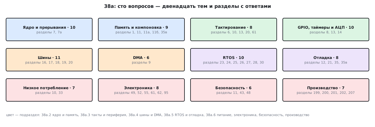
| Topic | Questions | How many | Sections |
|---|---|---|---|
| Core and interrupts | 1–10 | 10 | 7, 7а |
| Memory and linking | 11–19 | 9 | 1, 11, 11а, 11б, 35в |
| Clocking | 20–27 | 8 | 6, 10, 13, 20, 61 |
| GPIO, timers and ADC | 28–37 | 10 | 8, 13, 14 |
| Buses | 38–48 | 11 | 16, 17, 18, 19, 20 |
| DMA | 49–54 | 6 | 9 |
| RTOS | 55–64 | 10 | 23, 24, 25, 26, 27, 28, 30 |
| Debugging | 65–72 | 8 | 12, 21, 35, 35в |
| Low power | 73–79 | 7 | 10, 33 |
| Electronics | 80–87 | 8 | 49, 52, 55, 61, 62, 95 |
| Security | 88–93 | 6 | 11, 43, 48 |
| Production | 94–100 | 7 | 199, 200, 201, 202, 207 |
Levels: junior — 33, middle — 43, senior — 24. Answer out loud without peeking, and then check against the section: that way you see not only "know — don't know", but also where an answer rests on words rather than on understanding.
38а.2 Core, interrupts, memory and linking
Core and interrupts
1. How does an interrupt differ from an exception in ARM terms? junior
An interrupt comes from the hardware, an exception is raised by the processor itself — for example, by an access to a non-existent address. In ARM an interrupt is considered a special case of an exception.
→ section 7 "Interrupts and exceptions"
2. How many cycles does entry into an interrupt handler take? junior
On Cortex-M3 and M4 — 12 cycles (plus Flash wait states), on M0 — 16, on M0+ — 15. The hardware itself saves the context; not a single program instruction is executed during that time.
→ section 7 "Interrupts and exceptions"
3. What does the core itself push onto the stack on exception entry? middle
8 words: R0–R3, R12, LR, PC, xPSR, plus a padding word if the stack was not divisible by 8 (bit 9 of xPSR). A frame with the FPU is 26 words.
→ section 7а "Exception entry from the inside: the stack frame, EXC_RETURN and the FPU"
4. What is in LR inside an exception handler? senior
EXC_RETURN: 0xFFFFFFF9 — return to the main code on MSP, 0xFFFFFFFD — on PSP, 0xFFFFFFE9 — with an FPU frame.
→ section 7а "Exception entry from the inside: the stack frame, EXC_RETURN and the FPU"
5. How many priority levels does an STM32 have, and which one is more urgent? junior
An STM32 has 16 priority levels, a smaller number is more urgent; the F0 and G0 have 4 priority levels. Assign them by the required response speed, not by the importance of the task.
→ section 7 "Interrupts and exceptions"
6. What does NVIC_SetPriorityGrouping(3) mean? senior
The CMSIS function takes the number of the PRIGROUP field, not the number of preemption bits: 3 means four preemption bits, 4 means three preemption bits and one subpriority bit.
→ section 7 "Interrupts and exceptions"
7. Why does a typo in a handler name not cause a build error? junior
A handler is bound by the function name: a typo causes no compilation error, the interrupt simply goes to an empty stub.
→ section 7 "Interrupts and exceptions"
8. Why is the EXTI handler called again and again? junior
The flag is not cleared: EXTI->PR is cleared by writing a one. Otherwise the handler loops forever.
→ section 7 "Interrupts and exceptions"
9. Can you put interrupts on PA3 and PB3 at the same time? middle
No: there are sixteen EXTI lines, and line number n serves pin n of only one port. Lines 5…9 and 10…15 share a common vector.
→ section 7 "Interrupts and exceptions"
10. What do tail-chaining and late-arriving exceptions give you? senior
Tail-chaining: a handler has finished and another exception is already pending — the core does not pop the frame off the stack and goes straight to the next handler. Tail-chaining and late-arriving exceptions save the saving and restoring of the frame.
→ section 7а "Exception entry from the inside: the stack frame, EXC_RETURN and the FPU"
Memory and linking
11. Why does a variable with an initial value take up space twice? junior
In Flash for the image and in RAM for itself. const keeps large tables in Flash only.
→ section 11 "Memory, linking, loading"
12. Why is a stack overflow dangerous? junior
The stack and the heap grow towards each other; a stack overflow gives no error but silently corrupts the neighbouring data. Large buffers are made static, not local.
→ section 11 "Memory, linking, loading"
13. At what address does Flash start on an STM32? junior
Flash on an STM32 starts at 0x0800 0000 and is mirrored at 0x0000 0000 when booting from Flash (BOOT0 = 0). The 4 GB address space is the same on all Cortex-M.
→ section 1 "The microcontroller as such"
14. How does Flash erasing on the F1 differ from the F4? middle
The erase unit: on the F1 a 1 KB page, on the F4 a sector from 16 to 128 KB (on the larger F1 parts a page is 2 KB). On the F1 Flash is programmed only in half-words at even addresses.
→ section 11 "Memory, linking, loading"
15. How do you store settings in Flash so that a power loss corrupts nothing? senior
As a log on two pages: records in a row, only the page with obsolete records is erased, each record has a sequence number and a CRC. The endurance grows 64 times.
→ section 11 "Memory, linking, loading"
16. What must an application that is started by a bootloader do? middle
Move SCB->VTOR to its own vector table, otherwise interrupts will go to someone else's handlers.
→ section 11 "Memory, linking, loading"
17. How many regions does the Cortex-M4 MPU have, and what is it for? senior
8 regions, size 2^(SIZE+1) from 32 bytes, the base aligned to the size. The main uses: a null pointer trap, a stack guard, forbidding execution from data.
→ section 11а "MPU: protecting memory from your own mistakes"
18. Why does DMA on the F7 and H7 deliver into the buffer something other than what arrived? senior
The data cache gets in the way: transmitting without a clean and receiving without an invalidate gives 64 wrong bytes out of 64 in the model. Alignment to 32 and a length that is a multiple of 32 remove the problem with neighbours on the cache line.
→ section 11б "Cache, TCM and memory domains on F7 and H7"
19. What in RAM survives a restart? senior
A system reset (the button, the watchdogs, software) does not touch RAM, removing power erases it. The startup code does not zero the NOINIT region.
→ section 35в "A failure in the field: a state snapshot that survives a reset, and analysis after reboot"
38а.3 Clocking, GPIO, timers and ADC
Clocking
20. What clock does an STM32 run from right after reset? junior
From the internal RC oscillator: 8 MHz on the F1, 16 MHz on the F4. Everything else has to be configured.
→ section 6 "Clocking (RCC)"
21. In what order do you switch the chip to the PLL? middle
Crystal → Flash wait states → bus prescalers → PLL → switch-over. The Flash wait states come before raising the frequency, otherwise a HardFault.
→ section 6 "Clocking (RCC)"
22. What is the APB1 frequency limit on the F1 and F4? junior
On the F1 APB1 is no higher than 36 MHz, on the F4 no higher than 42. Hence the bus prescalers.
→ section 6 "Clocking (RCC)"
23. What frequency do timers on a bus with a prescaler count from? middle
Timers on an APB bus with a prescaler greater than 1 get twice its frequency; on the F4 this also applies to APB2: TIM1 and TIM8 at 168 MHz count from 168 MHz.
→ section 13 "Timers (TIM)"
24. Why does USB need a crystal and not the HSI? middle
USB requires exactly 48 MHz with an accuracy of ±0.25 %; the HSI with its ±1 % does not qualify. On the F4 the Q divider in the PLL is responsible for the 48 MHz.
→ section 20 "USB"
25. How do you wait correctly for the switch to the PLL? middle
Always wait for readiness with a timeout, and read the confirmation of the switch from SWS, not from SW.
→ section 6 "Clocking (RCC)"
26. How do you calculate the crystal capacitors, and what does a mistake cost? senior
By the formula 2 × (CL − Cstray); a 5 pF error for a watch crystal means 39 minutes a year.
→ section 61 "Minimal circuitry around a microcontroller: start-up conditions"
27. What happens to the clocking after leaving Stop? middle
After Stop the clocking is reset to the HSI — the crystal and PLL configuration must be applied again.
→ section 10 "Power and power saving"
GPIO, timers and ADC
28. Which register do you use to change the state of an output? junior
Through BSRR/BRR — atomic set and reset of a bit, not through ODR.
→ section 8 "Input/output ports (GPIO)"
29. What state are the pins in after reset? junior
All pins except the debugger pins are floating inputs, on the F1 CRL/CRH = 0x44444444. A port does not work until its clock is enabled in RCC.
→ section 8 "Input/output ports (GPIO)"
30. Why choose the pin speed? middle
The pin speed is about electromagnetic compatibility, not performance: it is the edge rate (OSPEEDR on the F4).
→ section 8 "Input/output ports (GPIO)"
31. Why is it risky to use PA13 and PA14? junior
They are taken by SWD; by freeing them you lose debugging.
→ section 8 "Input/output ports (GPIO)"
32. How do you calculate the frequency of timer events? junior
Frequency = f / ((PSC + 1) × (ARR + 1)); the prescaler is taken as small as possible so that ARR is larger — that is the PWM resolution.
→ section 13 "Timers (TIM)"
33. Why does a new ARR value take effect in the middle of a period? middle
PSC is always buffered, ARR and CCR only with preload (ARPE, OCxPE; it is off after reset). With it the new values take effect on the update event.
→ section 13 "Timers (TIM)"
34. PWM on TIM1 is configured, but the pin is silent. Why? middle
On TIM1 and TIM8 the outputs are enabled by the MOE bit; without it everything is configured, but the pin is silent.
→ section 13 "Timers (TIM)"
35. What is the step of a 12-bit ADC with a 3.3 V reference? junior
About 0.8 mV; the accuracy is no better than the accuracy of the reference.
→ section 14 "Analog-to-digital converter (ADC)"
36. Why does the ADC give readings that are low but plausible? middle
Too little sampling time for such a source: on the F1, 1.5 cycles allow a source of up to 0.4 kΩ, 55.5 up to 50 kΩ.
→ section 14 "Analog-to-digital converter (ADC)"
37. How do you measure your own supply voltage without external parts? senior
Using VREFINT: on the F4 VDDA = 3300 × VREFINT_CAL / code with the factory code, on the F1 from the nominal 1.2 V. The sampling time for internal channels is the longest one.
→ section 14 "Analog-to-digital converter (ADC)"
38а.4 Buses and DMA
Buses
38. How does the TXE flag differ from TC on a UART? junior
TXE — you can put in the next byte, TC — everything has physically gone out. Do not confuse them.
→ section 16 "UART / USART"
39. How do you receive variable-length packets over UART? middle
By the gap on the line; the best scheme is DMA plus the IDLE interrupt.
→ section 16 "UART / USART"
40. Why does the UART interrupt spin endlessly? middle
An ORE overrun is pending: on the F1 and F4 it is cleared by reading SR, then DR; a flag left set makes the interrupt loop.
→ section 16 "UART / USART"
41. What pull-ups does an I²C bus need? junior
Both pins are open-drain, pull-up resistors are mandatory: 4.7 kΩ for 100 kHz, 2.2 kΩ for 400 kHz.
→ section 17 "The I²C bus"
42. How do you revive a stuck I²C bus? senior
With nine SCL clocks by hand and a software reset of the block. All waits for flags in production code only with timeouts.
→ section 17 "The I²C bus"
43. What does the CR2.FREQ field set on the I²C of the F1 and F4? middle
It is the APB1 bus frequency, not the I²C speed; the speed is set by CCR.
→ section 17 "The I²C bus"
44. Why, in SPI, do you have to transmit something to read a byte? junior
The exchange is always two-way: to receive a byte you must transmit one, any one.
→ section 18 "The SPI bus"
45. What happens with the wrong SPI mode? middle
The mode is set by CPOL and CPHA, the common ones are 0 and 3. A wrong mode gives no error: in the model 0x9F is read as 0x4F, and sometimes correctly — for the time being.
→ section 18 "The SPI bus"
46. How many terminators go on a CAN bus? junior
Exactly two, 120 Ω each, at the ends of the line; a transceiver is mandatory.
→ section 19 "The CAN bus"
47. Which CAN frame wins arbitration? middle
The message is addressed, not the recipient; a smaller identifier has a higher priority. A frame holds at most 8 bytes.
→ section 19 "The CAN bus"
48. Why is a BluePill not detected over USB? junior
A 1.5 kΩ pull-up on D+ is mandatory; on BluePill clones the value is often wrong, and that is the main cause of "not detected".
→ section 20 "USB"
DMA
49. What does DMA give you? junior
It frees the core: the interrupt comes once per whole buffer, not on every byte.
→ section 9 "Direct memory access (DMA)"
50. How does DMA on the F1 differ from the F4? middle
The F1 has channels with a fixed peripheral mapping, the F4 has streams with channel selection, a FIFO, burst transfers and double buffering. Code does not port between them.
→ section 9 "Direct memory access (DMA)"
51. How many items does DMA transfer per configuration? junior
The counter is 16-bit: at most 65535 items per configuration.
→ section 9 "Direct memory access (DMA)"
52. How do you get a continuous stream through DMA without losses? middle
Circular mode plus half-transfer and transfer-complete interrupts: while DMA fills the second half, you process the first, and vice versa.
→ section 9 "Direct memory access (DMA)"
53. Where do you place DMA buffers on the F4? middle
Static, in ordinary SRAM (not in CCM), aligned, volatile; on the F7 and H7 you also have to deal with the cache.
→ section 9 "Direct memory access (DMA)"
54. How do you get PWM from a table without involving the processor? senior
DMA writes to any peripheral register: table → the timer's CCR on a request from another timer (UDE), including in sleep.
→ section 9 "Direct memory access (DMA)"
38а.5 RTOS and debugging
RTOS
55. What is the scheduler's rule, and what does "real time" mean? junior
The ready task with the highest priority runs. "Real time" means a predictable deadline, not speed.
→ section 23 "Why you need an operating system"
56. How much does a context switch cost on Cortex-M? middle
Nineteen instructions: the processor saves half of the registers by itself.
→ section 23 "Why you need an operating system"
57. In what units is the stack depth of a FreeRTOS task given? junior
In words: 128 means 512 bytes. Checking the result of xTaskCreate is a must.
→ section 24 "How FreeRTOS is organized"
58. How does vTaskDelay differ from xTaskDelayUntil? middle
vTaskDelay gives a period equal to the delay plus the run time; for an exact period you need xTaskDelayUntil.
→ section 26 "Tasks"
59. Which FreeRTOS heap scheme should you choose? middle
heap_4 is the default choice; heap_1 has no freeing, heap_3 is a wrapper around malloc, heap_5 is for several memory regions.
→ section 25 "Memory management"
60. Which FreeRTOS functions can be called from an interrupt? junior
Only the twins ending in FromISR; they have no wait time, but they do have a wake-up flag.
→ section 27 "Queues"
61. What happens if you forget portYIELD_FROM_ISR? senior
The reaction is postponed until the next tick — three orders of magnitude longer than the switch itself: the FromISR functions only set a flag.
→ section 28 "Interrupts in an RTOS"
62. What priority can you give an interrupt that calls FromISR? senior
No more urgent than the threshold: the kernel masks up to the threshold through BASEPRI, threshold 5 on an STM32 is 0x50. The default priority is zero, that is, forbidden.
→ section 28 "Interrupts in an RTOS"
63. What is priority inversion, and does a mutex help? senior
A high-priority task waits for a low-priority one that has been preempted by a medium-priority one. A mutex inherits the priority: inheritance bounds the wait but does not remove it — hold a mutex briefly.
→ section 30 "Synchronization and thread safety"
64. Does volatile protect a counter from a race? middle
No: counter++ is three instructions, and a switch between them loses the increment. volatile does not protect against a race.
→ section 30 "Synchronization and thread safety"
Debugging
65. How do you find the instruction where a HardFault happened? middle
The seventh word of the frame is the faulting PC; under an RTOS the stack (MSP or PSP) is chosen by bit 2 in LR.
→ section 35 "Debugging"
66. IMPRECISERR points at the wrong instruction. What do you do? senior
CFSR is a byte, a byte and a half-word for the three faults; IMPRECISERR points at the wrong instruction and is cured with DISDEFWBUF; FORCED in HFSR is an escalation.
→ section 35 "Debugging"
67. How do you find out how much stack a task has left? middle
The stack is filled with 0xA5; the remainder is counted by untouched bytes, in words, and it is the minimum over the whole run time.
→ section 35 "Debugging"
68. How often should you read DWT->CYCCNT for load statistics? senior
The cycle counter at 72 MHz overflows in 59 seconds, on the F4 at 168 MHz even faster: read it more often.
→ section 35 "Debugging"
69. Why is SWO better than debug output over UART? junior
It does not occupy a UART: besides SWD you need only the SWO pin (PB3); it is an order of magnitude faster than UART, but works only with a debugger connected. 2 MHz gives 100 000 characters per second, UART at 115 200 gives 11 520.
→ section 21 "SWO and ITM debug output"
70. Why does single-stepping a system with an RTOS deceive you? middle
Single-stepping under an RTOS deceives you: time stands still. For the question "who wrote this" there is a watchpoint.
→ section 35 "Debugging"
71. How do you save information about a failure in the field? senior
The handler writes a crash record — 88 bytes, CRC last — into the NOINIT region at the end of RAM and resets the chip through SYSRESETREQ; the analysis comes after the reboot.
→ section 35в "A failure in the field: a state snapshot that survives a reset, and analysis after reboot"
72. Why does the board reboot at a breakpoint? middle
During debugging the watchdogs are stopped with the DBGMCU->CR bits (on the F4 — DBGMCU->APB1FZ), otherwise the board reboots at breakpoints.
→ section 12 "Service blocks: watchdog timers, CRC, RTC"
38а.6 Power, electronics, security and production
Low power
73. What sleep modes does an STM32 have? junior
Sleep (the core sleeps), Stop (the clocks sleep, memory is intact), Standby (everything is off except the backup domain).
→ section 10 "Power and power saving"
74. How do you tell a wake-up from Standby from a cold start? middle
Leaving Standby is a reset; you can tell it from a cold start by the SBF flag.
→ section 10 "Power and power saving"
75. Why does the chip not go into Stop? middle
Stop happens only if the pending EXTI, peripheral and RTC alarm flags are cleared; otherwise the program continues after WFI.
→ section 10 "Power and power saving"
76. Why does the chip wake up from Standby immediately? senior
CWUF is not cleared: it is cleared before entry — last, after EWUP.
→ section 10 "Power and power saving"
77. What decides battery life when waking once a second? middle
Above all, the length of the burst; one forgotten pull-up on a pin held at the opposite level cuts it in half.
→ section 10 "Power and power saving"
78. How does FreeRTOS sleep when idle, and how long can it sleep? senior
Tickless mode stops SysTick, reprograms it for the whole idle time and goes to sleep with WFI. The limit of one sleep on SysTick at 72 MHz is 233 ms.
→ section 33 "Configuration and power saving"
79. What should you do before measuring sleep current? junior
Put unused pins into analog mode (except SWD) and clear the debug bits in DBGMCU->CR — the reset button does not clear them.
→ section 10 "Power and power saving"
Electronics
80. How much current can you draw from a microcontroller pin? junior
One pin up to 20 mA, all together up to 100 mA; design for 8–10.
→ section 49 "Voltage, current, power: Ohm's law and first calculations"
81. What decoupling does the microcontroller supply need? junior
100 nF right next to each supply pin, plus a common 4.7 µF and a separate filter on the analog supply; on the F4 — 2.2 µF of ceramic each on VCAP_1 and VCAP_2.
→ section 61 "Minimal circuitry around a microcontroller: start-up conditions"
82. Do you need an external resistor on NRST? middle
No: the reset pin already has a 25…55 kΩ pull-up. A 100 nF capacitor gives a 4.8 ms reset.
→ section 61 "Minimal circuitry around a microcontroller: start-up conditions"
83. How do you protect an ordinary input from 24 V? senior
Limit the injection current through the diode that is already there: 5 mA per pin and 25 mA in total. The resistor is the excess over 4.0 V divided by 5 mA: 4.7 kΩ for 24 V; you cannot do this on a tolerant pin.
→ section 62 "Pin protection"
84. What does a "5 V tolerant" pin mean? middle
A tolerant pin withstands 5.5 V, but only while power is applied; the operating range of an ordinary one is from −0.3 V to the supply plus 0.3 V.
→ section 62 "Pin protection"
85. Why does a field-effect transistor not turn on from a 3.3 V pin? middle
An ordinary field-effect transistor with 3.3 V on the gate is almost off: take one whose channel resistance is specified at 2.5–2.7 V; the threshold Vgs(th) is no good for choosing.
→ section 52 "Driving loads: switches, relays, MOSFETs, drivers"
86. Why did the regulator start oscillating after a capacitor was replaced? senior
The output capacitor is part of the loop: ceramic instead of electrolytic turns the regulator into an oscillator.
→ section 55 "Linear regulators"
87. How do you choose the I²C pull-up by the rise time? middle
An I²C edge rises in 0.8473·R·C and must fit into 1000 ns at 100 kHz and 300 ns at 400 kHz.
→ section 95 "How to connect sensors: power, pull-ups, levels, wires"
Security
88. How do you remove firmware read protection? junior
Only with a full erase; the second level is irreversible on some families. On the F4 the value 0xCC disables debugging for good.
→ section 11 "Memory, linking, loading"
89. Does an image CRC protect against firmware substitution? middle
No: a CRC catches corruption but not substitution — a signature protects against substitution.
→ section 48 "Your own bootloader and firmware updates"
90. Which AES mode should you choose? middle
AES in GCM mode — encryption with authentication; do not use ECB; an IV in CTR and GCM with the same key is never repeated.
→ section 43 "Hardware cryptography: CRC, RNG, HASH, CRYP"
91. What do you check when reading the hardware random number generator? senior
The SECS and CECS flags are read before the data, otherwise you get non-random "random" numbers. A word is ready in ~40 cycles of 48 MHz.
→ section 43 "Hardware cryptography: CRC, RNG, HASH, CRYP"
92. Why is a firmware update without rollback dangerous? middle
Confirmation that the firmware works and rollback are a mandatory part, otherwise one bad firmware costs a trip to the device.
→ section 48 "Your own bootloader and firmware updates"
93. Where do you keep encryption keys, and why have a hardware block then? middle
Keys are not kept in the sources. The hardware block is an accelerator for the library, not its replacement.
→ section 43 "Hardware cryptography: CRC, RNG, HASH, CRYP"
Production
94. What do you hand over to the factory to assemble a board? junior
Four files: Gerber with drill data, the bill of materials, the placement file, the assembly drawing; one archive, with the version in the name.
→ section 199 "Board assembly at the factory: the bill of materials, the placement file and Gerber"
95. Where do you start the first power-on of a new board? junior
Inspection → continuity check → power with a current limit → test points → SWD → test firmware. The supply is 3.3 V with a 20 mA limit.
→ section 200 "First power-on of a new board"
96. What is the SW-DP port code on the F1 and F4? middle
0x1BA01477 on the F1, 0x2BA01477 on the F4. No response — check the adapter, the chip's supply, NRST, the SWD lines, BOOT0.
→ section 200 "First power-on of a new board"
97. What question does a test on the production line answer? middle
Not "is the code correct" but "is the board assembled"; the verdict is pass/fail plus a line in the log. The cycle time at 200 boards per shift is 144 s for everything.
→ section 201 "Production testing and programming on the line"
98. When are the option bytes and protection set on the line? senior
As the last step: WDG_SW=0, BOR_LEV according to the supply, RDP level 1 at the very end; level 2 is irreversible.
→ section 201 "Production testing and programming on the line"
99. What does the ST factory calibrate, and what is left to you? senior
The factory calibrates only the die: on the F407 the system memory holds VREFINT_CAL and TS_CAL1/TS_CAL2. The rest is done on the line: one point removes the offset, two points remove the offset and the slope.
→ section 202 "Calibration on the line"
100. What ESD robustness does the datasheet give for the F103 and F407? middle
2000 V in the human body model (class 2) and 500 V in the charged device model, while a discharge can be felt from about 3 kV.
→ section 207 "The assembly workstation: static, SMD soldering, cleaning"
38а.7 Pitfalls
"volatile makes a counter thread-safe." No: volatile means
"read memory every time", while counter++ is three instructions, and
a switch between them loses the increment (sections 30 and 124).
"Priority 0 is the weakest." The other way round: on an STM32 a smaller number is more urgent. And for FreeRTOS the default interrupt priority is zero, that is, forbidden (sections 7 and 28).
"Real time means fast." "Real time" means a predictable deadline, not speed (section 23).
"A CRC protects the firmware." A CRC catches corruption but not substitution — a signature protects against substitution (section 48).
"Stop and Standby are almost the same thing." They are distinguished by one bit, PDDS,
but the consequences differ: the program continues versus a reset (section 10).
"Pull-ups on I²C are optional." Both pins are open-drain, pull-up resistors are mandatory (section 17).
A number without a chip. On the F1 APB1 is no higher than 36 MHz, on the F4 no higher than 42; after reset the chip runs from the RC oscillator — 8 MHz on the F1, 16 MHz on the F4. Name the family together with the number (section 6).
38а.8 Summary
- 100 questions in 12 topics, references to 42 sections; 33 junior, 43 middle, 24 senior.
- Most often the answers lead to section 7 (7 questions), section 10 (7 questions) and section 9 (6 questions).
- The answers contain 187 key phrases and numbers, and each one is found word for word in the text of the referenced section.
- Every "section N" reference leads to an existing section, and the title matches; there are no duplicate questions.
Next: section 41 "External memory: SPI Flash, NAND, SD".