 Embedded HandbookApps
168. Inductors, chokes and ferrite beads: LC filter, resonance, saturation
On a microcontroller board an inductor shows up in four roles: the inductor of a switching converter (section 58), a supply filter for the analog section, a ferrite bead on a supply line, and a common-mode choke on lines that go out into a cable. The voltage spike when a relay coil is switched off is covered in sections 51.2 and 161.6. This section covers where an inductor lets you down: a filter with it resonates, a bead is not a bead at low frequencies, an inductor saturates earlier than you think — and how a common-mode choke separates noise from signal.
All numbers below come from ngspice models and calculations.
Terms used in the documentation
Term Meaning inductance (L) inductance DC resistance (DCR) winding resistance to DC saturation current (Isat) current at which inductance drops rated (heating) current (Irms) current limit set by heating incremental inductance differential inductance, dΦ/dI self-resonant frequency (SRF) frequency where L and winding capacitance resonate shielded / unshielded inductor inductor with / without a magnetic shield ferrite bead ferrite bead impedance at 100 MHz impedance at 100 MHz LC filter LC filter damping adding losses to suppress resonance resonance peaking gain rise at resonance common-mode choke choke that blocks in-phase noise differential mode / common mode antiphase (differential) / in-phase (common) signal coupling coefficient how tightly the windings are coupled leakage inductance uncoupled part of the winding inductance
168.1 The inductor: current cannot change in a step
The voltage across an inductor is U = L · di/dt. Apply 5 V to 10 µH and the current
rises by 0.5 A per microsecond until something limits it. The energy
stored in the inductor is L · I² / 2: 5 µJ at 1 A. The inductor
gives this energy back when the circuit is broken, and if it has nowhere to go you get
a voltage spike (sections 51.2 and 161.6).
That is also where the benefit comes from: the inductor resists fast changes of current, that is, it passes DC and holds back AC — a filter.
168.2 The LC supply filter and its resonance
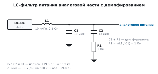
The analog section is powered from a switching regulator through a
10 µH inductor (winding resistance 0.1 Ω) and a 10 µF ceramic, with a
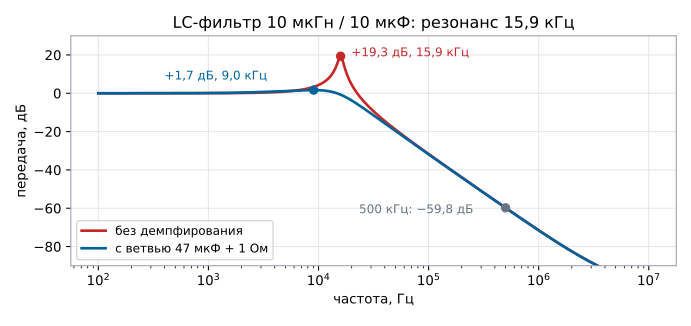
10 mA load. The resonant frequency f = 1 / (2π · √(L · C)) = 15.9 kHz,
the characteristic impedance √(L / C) = 1 Ω.
| Filter | Peaking at resonance | At 500 kHz |
|---|---|---|
| no damping | +19.3 dB at 15.9 kHz | −59.8 dB |
| with a 47 µF + 1 Ω branch | +1.7 dB at 9.0 kHz | −59.8 dB |
At the 500 kHz converter frequency the filter is excellent: 50 mV of ripple becomes 0.05 mV. But near resonance it amplifies: anything that arrives at 16 kHz — noise from the load, an audio frequency, beating between two converters — reaches the analog supply 9.3 times larger. There is little resistance in the loop: 0.1 Ω of winding and 5 mΩ of ceramic against 1 Ω of characteristic impedance — a Q of about ten.
The cure is losses at resonance: in parallel with the ceramic you place a larger
capacitor (47 µF) in series with a resistor of about √(L / C), here
1 Ω. At high frequency this branch does no harm, but it damps the resonance.
168.3 A ferrite bead is not a resistor at all frequencies
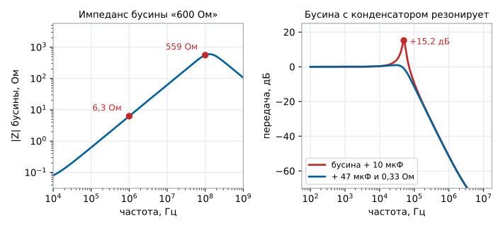
A bead is labelled with a single number, for example "600 Ω at 100 MHz". A model of such a bead: 50 mΩ to DC, followed by 1 µH in parallel with 600 Ω and 1.5 pF.
| Frequency | Bead impedance |
|---|---|
| 1 MHz | 6.3 Ω |
| 100 MHz | 559 Ω |
| maximum, 130 MHz | 600 Ω |
At one megahertz the bead is just a 1 µH inductance: 2π · 1 MHz · 1 µH = 6.28 Ω. It becomes a resistor that absorbs noise only at tens of megahertz. And together with a 10 µF capacitor after it, it is the same LC filter — with a resonance at 50.3 kHz:
| Bead and 10 µF | Peaking at resonance | At 1 MHz |
|---|---|---|
| no damping | +15.2 dB | −51.5 dB |
| with a 47 µF + 0.33 Ω branch | +1.0 dB | −51.6 dB |
Noise at 50 kHz after the "filtering" bead is 5.7 times larger than before it. Beads are used against noise at tens and hundreds of megahertz; for kilohertz noise use an inductor with a resonance calculation and damping.
The number on the bead is at zero current. "600 Ω at 100 MHz" is measured without DC current, but a bead on a supply line always carries it. The current saturates the ferrite (as in an inductor, 168.4), the inductance drops, and the impedance drops with it: for small beads at around the rated current, by several times. If the inductance in the model above dropped threefold, 239 Ω would remain at 100 MHz instead of 559. For a bead on a supply line, look at the impedance graph at the working DC current, and take the rated current with margin.
168.4 Saturation: the current beyond which there is no inductor
An inductor core saturates: above a certain current the inductance drops, and the current rises almost unrestrained. In the documentation the "saturation current" is the current at which the inductance has dropped by a specified fraction, usually by 30 %.
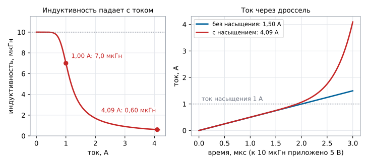
A model of a 10 µH inductor with a saturation current of 1.00 A (the inductance drops to 7 µH). 5 V is applied to it for 3 µs:
| Inductor | Current after 3 µs |
|---|---|
| no saturation | 1.50 A |
| with saturation | 4.09 A |
Up to 1 A both go together — the saturating one reaches it in 1.91 µs — but after that its current shoots up: in the remaining 1 µs it nearly quadruples. In a converter this means a current peak through the switch, a protection trip, or a burned transistor.
Why it is so abrupt can be seen from the inductance on the left graph. Here it is
the differential inductance — dΦ/dI, the increase of flux for each additional ampere:
that is what sets the rate of current rise U / L. At 1 A it is 7.0 µH, at
4.09 A at the end of the pulse it is 0.60 µH, 17 times below the rated value. The
less inductance is left, the faster the current rises, and the higher the current,
the less inductance remains — the process accelerates itself.
How to calculate the peak. A 12 V → 3.3 V buck converter, 500 kHz,
10 µH, 1 A load: the peak-to-peak inductor current ripple
(Uin − Uout) · D / (f · L) = 0.48 A, the peak current is 1 A + 0.24 = 1.24 A.
An inductor with a 1 A saturation current is already saturating here; you need a saturation current
above the peak with margin (choosing the inductor by ripple is section 58.2).
168.5 Common-mode choke: the signal passes, the noise does not
On lines that leave the board into a cable — CAN, RS-485, USB — a common-mode choke is fitted: two identical windings on a common core, one in each line, with the winding starts on the same side (the dots on the schematic).
- The useful signal travels along the pair in antiphase: current goes out along one line and returns along the other. The fluxes of the windings subtract — for the signal the choke almost disappears.
- Noise induced on the cable arrives on both lines in phase. The fluxes add up — each line sees the full inductance.
For the same reason the line current does not saturate the core: the forward and return currents cancel each other's flux. That is why a common-mode choke of tens of microhenries can be the size of a resistor.
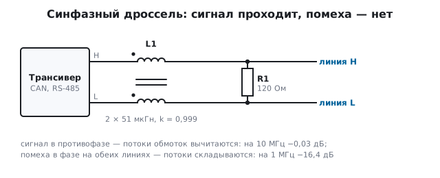
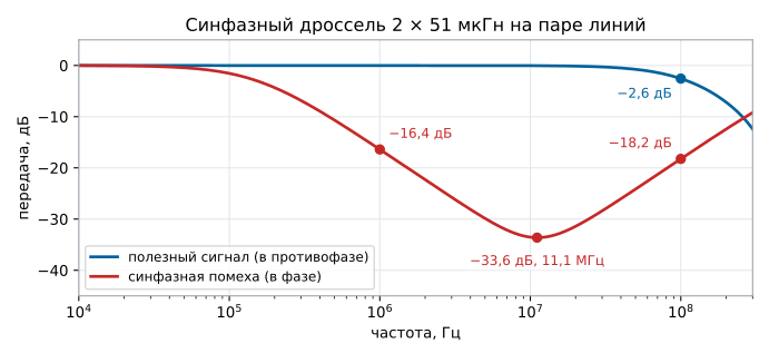
Model: windings of 51 µH each, coupling 0.999, capacitance of each winding 2 pF and core losses 4.7 kΩ; the load is a 120 Ω terminator between the lines and 100 Ω from each line to ground. The load is the same, the only difference is how the voltage is applied:
| Frequency | Antiphase signal | In-phase noise |
|---|---|---|
| 100 kHz | 0.00 dB | −1.5 dB |
| 1 MHz | 0.00 dB | −16.4 dB |
| 10 MHz | −0.03 dB | −33.5 dB |
| 100 MHz | −2.57 dB | −18.2 dB |
At one megahertz the noise is attenuated 6.6 times, while the signal does not notice the choke.
The choke suppresses noise most strongly at 11.1 MHz (−33.6 dB): there
the winding inductance resonates with its own capacitance, and only
the core losses remain. Above resonance the choke is already a capacitor, and at
100 MHz the noise passes again (−18.2 dB) — choose the choke from the
common-mode impedance graph in the documentation, for the noise frequency. The signal at
100 MHz loses 2.6 dB: the winding coupling is not ideal, and the antiphase current does
see the leakage inductance L · (1 − k) = 51 nH per winding.
168.6 How to read an inductor datasheet
- Two currents. The saturation current is about inductance, the heating current is about winding temperature. The working peak current must be below the first, the RMS current below the second.
- Winding resistance heats and drops voltage: 0.1 Ω at 1 A means 0.1 W and 0.1 V.
- Shielded or not. An unshielded inductor is cheaper, but its field induces noise on neighbouring traces, and it picks up noise from others itself.
- Self-resonance. Above it the inductor is a capacitor; for noise filters this is the edge of the working band.
- Inductance tolerance is usually ±20 %: calculate the filter resonance with this spread.
- A common-mode choke is described by two impedance graphs — common-mode and differential-mode — and by the allowed line current.
168.7 Pitfalls
After an LC filter the analog noise grew at some frequency.
Filter resonance without damping; add a capacitor + resistor branch of about
√(L/C).
A bead did not help against noise at tens of kilohertz — it got worse. At low frequency the bead is an inductance, and it resonates with the capacitor.
The converter goes into protection at full load. The inductor was chosen by average current; the peak is above the saturation current.
The inductor is hot although the saturation current has margin. The heating current is exceeded or the winding resistance is too high.
Noise from the converter on a neighbouring trace. An unshielded inductor next to analog circuits.
Noise from the cable at around a hundred megahertz gets through although a common-mode choke is fitted. The noise frequency is above the choke's self-resonance — there it is a capacitor; choose the choke from the common-mode impedance graph.
Signal edges are rounded off after the "common-mode choke". Two separate inductors were fitted: they have no common flux, and the signal sees the full inductance in each line.
168.8 Summary
- 5 V across 10 µH gives 0.5 A per microsecond; the energy at 1 A is 5 µJ.
- LC 10 µH / 10 µF: resonance at 15.9 kHz, without damping peaking of +19.3 dB (9.3 times), with a 47 µF + 1 Ω branch +1.7 dB; at 500 kHz −59.8 dB.
- A "600 Ω at 100 MHz" bead is 6.3 Ω at 1 MHz; with 10 µF it resonates at 50.3 kHz with +15.2 dB peaking, damping leaves +1.0 dB.
- An inductor with a 1 A saturation current at 5 V after 3 µs: 4.09 A instead of 1.50 A, inductance at the end of the pulse 0.60 µH; the peak current of a 12 → 3.3 V, 1 A, 500 kHz, 10 µH converter is 1.24 A.
- A 2 × 51 µH common-mode choke: in-phase noise at 1 MHz −16.4 dB, at 11.1 MHz −33.6 dB; the antiphase signal at 10 MHz loses 0.03 dB.
Next: section 169 "Diodes in detail".