 Embedded HandbookApps
167. Capacitors in detail: ceramic classes, ESR and ESL, decoupling, electrolytics
The rule "100 nF at every supply pin" is given in sections 53 and 61, RC circuits in section 50, the regulator output capacitor in 55. This section explains why the rule is what it is and where it breaks: ceramic capacitors lose capacitance with temperature and voltage, every capacitor has resistance and inductance, and on nanosecond edges what decides is not the capacitance but how the capacitor is soldered.
All numbers below come from ngspice models and from calculations based on the class definitions.
Terms used in the documentation
Term Meaning dielectric class (C0G / NP0, X7R, X5R, Y5V) class of the ceramic dielectric temperature characteristic how capacitance changes with temperature DC bias characteristic how capacitance depends on the DC voltage equivalent series resistance (ESR) resistance in series with the capacitance equivalent series inductance (ESL) inductance in series with the capacitance self-resonant frequency (SRF) frequency where C and ESL resonate anti-resonance parallel resonance between two capacitors decoupling / bypass capacitor capacitor that keeps a supply pin stable bulk capacitor larger energy-storage capacitor mounting inductance inductance added by pads, traces and vias endurance / load life service life under load ripple current allowed AC current through the capacitor voltage derating margin between working and rated voltage
167.1 Types of capacitors
| Type | Strengths | Weaknesses | Where it is used |
|---|---|---|---|
| C0G (NP0) ceramic | stable, lossless | low capacitance per package | crystal, filters, timing circuits |
| X7R / X5R ceramic | high capacitance in a small package, low ESR and ESL | capacitance depends on temperature and voltage | decoupling, bulk capacitors near pins |
| Y5V ceramic | even more capacitance | loses almost all of it | better not to use |
| aluminium electrolytic | high capacitance, cheap | dries out, high ESR when cold | power input, bulk |
| polymer | low ESR, lives longer than an electrolytic | more expensive | output of switching converters |
| tantalum | stable capacitance | fails short, needs voltage margin | older designs, regulators that require ESR |
167.2 Ceramic classes and temperature
A ceramic class is not a material "by eye" but a promised change of capacitance over a temperature range:
| Class | Range | Capacitance change |
|---|---|---|
| C0G (NP0) | −55…125 °C | 0 ± 30 ppm/°C |
| X7R | −55…125 °C | ±15 % |
| X5R | −55…85 °C | ±15 % |
| Y5V | −30…85 °C | +22…−82 % |
What this means for a 10 kΩ / 10 nF filter in front of an ADC (cutoff 1.59 kHz) at the worst point of the class:
| Capacitor | Capacitance | Cutoff |
|---|---|---|
| C0G, 60 °C of heating | 9.98 nF | 1.59 kHz |
| X7R, −15 % | 8.50 nF | 1.87 kHz |
| Y5V, −82 % | 1.80 nF | 8.84 kHz |
Y5V turns a 1.59 kHz filter into an 8.84 kHz filter — a bandwidth 5.6 times wider, and the noise from section 165 gets into the ADC. In timing and filter circuits use only C0G; X7R is for decoupling, where the exact capacitance does not matter.
167.3 DC voltage eats the capacitance
X7R and X5R ceramics lose capacitance not only with temperature but also with the DC voltage across them — and the parameter table usually says nothing about it: the dependence is given as a separate graph. The smaller the package and the closer the working voltage to the rated one, the larger the loss: a "10 µF" in a small package on a 5 V rail can turn out to be a few microfarads.
In practice: - look at the voltage dependence graph for the specific part number, not at the value printed on the reel; - for a given capacitance take a larger package or a higher rated voltage — the loss is smaller; - if a regulator needs a minimum output capacitance (section 55.7), check it at the working voltage and with a cold and a hot board.
C0G has no such dependence — one more reason to use it in filters.
167.4 A real capacitor: ESR, ESL and self-resonance
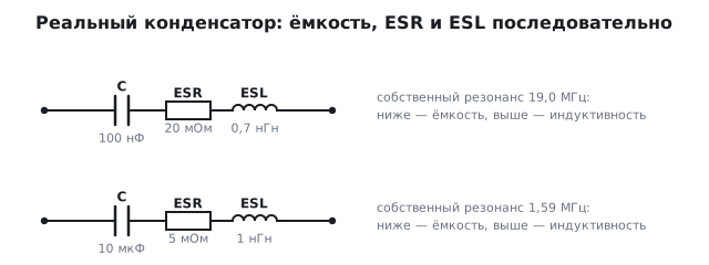
Every capacitor has, in series with its capacitance, a resistance
(ESR) and the inductance of its leads and plates (ESL). Below the self-resonant
frequency f = 1 / (2π · √(ESL · C)) it behaves as a capacitance, at that frequency
as just the ESR, and above it as an inductance.
| Capacitor | ESR | ESL | Self-resonance | Minimum impedance |
|---|---|---|---|---|
| 100 nF, 0603 package | 20 mΩ | 0.7 nH | 19.0 MHz | 20 mΩ |
| 10 µF, 0805 package | 5 mΩ | 1 nH | 1.59 MHz | 5 mΩ |
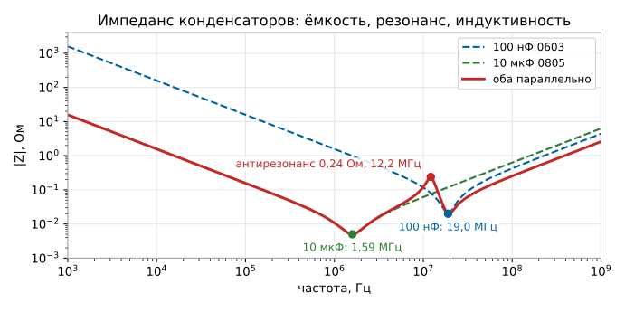
Above 19 MHz the "big" 10 µF and the "small" 100 nF are the same inductances of about a nanohenry: the capacitance no longer decides anything.
In parallel — anti-resonance. 100 nF and 10 µF side by side: between their resonances the 10 µF is already an inductance while the 100 nF is still a capacitance, and together they form a parallel tank. At 12.2 MHz the impedance of the pair rises to 0.24 Ω — three times higher than each capacitor alone at that frequency (0.08 Ω). The cure is losses: a bulk capacitor with a higher ESR, or several values so that the peaks do not coincide with the clock frequencies.
167.5 Decoupling: the mounting inductance decides
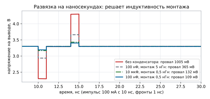
The MCU core draws current in pulses on the clock edges. Model: a 3.3 V regulator behind a trace of 10 nH and 50 mΩ, a 100 mA current pulse with a 1 ns edge:
| What is at the supply pin | Voltage dip |
|---|---|
| nothing | 1005 mV |
| 100 nF, 0.5 nH mounting | 109 mV |
| the same 100 nF, 5 nH mounting | 365 mV |
| 10 µF, 0.5 nH mounting | 132 mV |
| 10 µF in an 0603 package, 0.5 nH mounting | 108 mV |
Without a capacitor the dip is L · di/dt = 10 nH · 100 mA / 1 ns = 1 V:
on a nanosecond scale the trace to the regulator is not a wire. With a capacitor at the
pin the dip is 9 times smaller, but the same capacitor soldered through a
long trace and a via works three times worse. And the 10 µF
is worse here because it comes in an 0805 package with 1 nH versus 0.7 nH for the 0603.
The inductance is set by the package size and the mounting, not by the capacitance: a 10 µF in the same
0603 with the same mounting gives 108 mV — no worse than 100 nF.
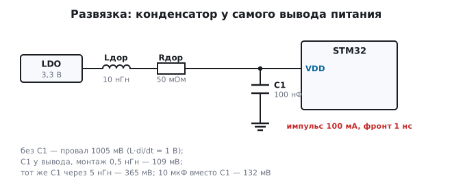
Hence the layout rules from section 130: the capacitor goes right at the pin, first the capacitor, then the via to the power plane, and the capacitor's ground goes straight to the ground plane through its own via.
167.6 Electrolytics and tantalums: lifetime and margin
An electrolytic dries out. The documentation gives the service life at the maximum temperature, and it doubles for every 10 °C below that. A capacitor rated 2000 h at 105 °C:
| Temperature in the case | Lifetime |
|---|---|
| 105 °C | 2000 h |
| 65 °C | 32000 h — 3.7 years |
| 45 °C | 128000 h — 14.6 years |
Placed next to a hot regulator, it will live several times shorter than in a cool corner of the board. It fails gradually: the capacitance falls, the ESR rises, the ripple rises — the device starts misbehaving long before it "pops".
Tantalum needs voltage margin. A tantalum fails short, often catching fire, from the inrush current at power-on. The usual practice is a working voltage no higher than half the rated one: for a 3.3 V rail use a capacitor rated 6.6 V or more, which means 10 V from the standard series. This rule applies to classic manganese dioxide tantalum. Polymer tantalum allows a much smaller margin (see the documentation of the series) and fails more gently, without fire.
167.7 Pitfalls
The ADC filter "drifts" when warm. A Y5V or X7R capacitor in the filter — use C0G.
The regulator oscillates although the output capacitance meets the datasheet. Ceramic capacitors lose capacitance at the working voltage; check it on the voltage dependence graph.
Noise at a frequency of about ten megahertz although there are plenty of capacitors. Anti-resonance of a pair of capacitors with different values — spread the values apart or add losses.
Glitches when pins switch, although the 100 nF is fitted. It is placed far away or through a long trace: the mounting inductance has eaten the decoupling.
"We fitted a 10 µF in a large package and it got worse." The package inductance is higher; on nanoseconds that is what decides, not the capacitance.
After a year or two the device started resetting. An electrolytic next to a hot part has dried out: the ESR has risen, and so has the supply ripple.
A tantalum capacitor burned at power-on. No voltage margin or an unlimited inrush current.
167.8 Summary
- Ceramic classes: C0G — 0 ± 30 ppm/°C, X7R — ±15 %, Y5V — down to −82 %; a 10 kΩ / 10 nF filter on Y5V moves from 1.59 kHz to 8.84 kHz.
- X7R/X5R ceramics lose capacitance with DC voltage — check the graph.
- Self-resonance: 100 nF 0603 — 19.0 MHz, 10 µF 0805 — 1.59 MHz; above it, an inductance. A parallel pair gives an anti-resonance of 0.24 Ω at 12.2 MHz.
- A 100 mA pulse with a 1 ns edge: without decoupling the dip is 1005 mV, 100 nF at the pin — 109 mV, the same through 5 nH — 365 mV, 10 µF — 132 mV, and in an 0603 package — 108 mV: the inductance is set by the package, not by the value.
- An electrolytic rated 2000 h at 105 °C lives 3.7 years at 65 °C and 14.6 years at 45 °C; tantalum — no more than half the rated voltage.
Next: section 168 "Inductors, chokes and ferrites".