 Embedded HandbookApps
169. Diodes in detail: drop versus current and temperature, Schottky leakage, recovery, power OR-ing
Section 51 covered the diode as a valve, the flyback diode across a coil and the Zener diode; section 62 covered clamps on signal lines. This section covers the properties that decide which diode goes where: the drop depends on current and temperature, a Schottky has a huge reverse current, a slow diode keeps conducting in reverse for a while after it is switched off, and an off diode is a capacitor.
All numbers below come from ngspice models with explicitly set parameters for three diodes: a silicon rectifier, a fast silicon signal diode and a Schottky. A specific part has its own figures, but the relationships are like these.
Terms used in the documentation
Term Meaning forward voltage (VF) voltage drop when conducting forward current (IF) current in the conducting direction reverse current / leakage (IR) current through the off diode reverse voltage (VR) voltage across the off diode reverse recovery time (trr) time to stop conducting in reverse junction capacitance (CJ) capacitance of the off junction temperature coefficient of VF change of the forward drop per degree Schottky barrier diode metal-semiconductor diode with a low drop fast recovery diode silicon diode with a short recovery time clamp diode diode that limits a line voltage diode OR-ing combining two supplies through diodes ideal diode controller MOSFET-based replacement for a diode
169.1 The forward drop depends on current
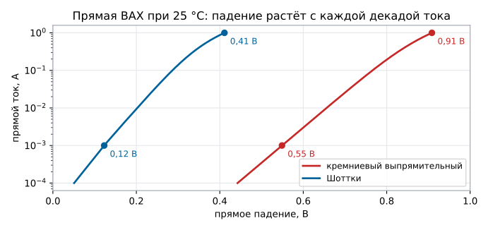
A diode has no "0.7 V drop" — it has a curve. At 25 °C:
| Forward current | Silicon rectifier | Schottky |
|---|---|---|
| 1 mA | 0.55 V | 0.12 V |
| 10 mA | 0.66 V | 0.20 V |
| 100 mA | 0.77 V | 0.29 V |
| 1 A | 0.91 V | 0.41 V |
The drop grows by roughly the same amount for each decade of current: about 0.11 V for the silicon diode and about 0.08 V for the Schottky; near one ampere the resistance of the leads and the die adds to it. At one ampere the diodes dissipate 0.91 and 0.41 W: the Schottky saves 0.50 W.
169.2 Forward drop and temperature
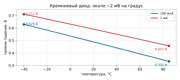
As it heats up, the drop decreases — for a silicon signal diode:
| Current | −40 °C | 25 °C | 85 °C | Drift |
|---|---|---|---|---|
| 100 µA | 0.629 V | 0.477 V | 0.332 V | −2.4 mV/°C |
| 1 mA | 0.711 V | 0.581 V | 0.457 V | −2.0 mV/°C |
The drift is almost linear, and the lower the current, the larger it is. This is both useful and harmful: - useful — a junction at constant current is a temperature sensor in itself; the built-in temperature sensors of microcontrollers work on the same principle; - harmful — two diodes in parallel do not share current equally: the warmer one conducts more, takes more current and heats up even more. Put them in parallel only with a resistor in each branch, or do not do it at all.
169.3 Reverse current: the price of the Schottky's low drop
An off diode with 5 V in the reverse direction:
| Diode | 25 °C | 85 °C |
|---|---|---|
| silicon signal | 2.5 nA | 214 nA |
| Schottky | 30 µA | 1.10 mA |
At room temperature the Schottky's reverse current is twelve thousand times higher than the silicon diode's, and heating to 85 °C raises it another 37 times. Where an off diode really has to block — battery power, high-impedance circuits, peak detectors — a Schottky can turn out worse than a "slow" silicon diode.
169.4 Reverse recovery
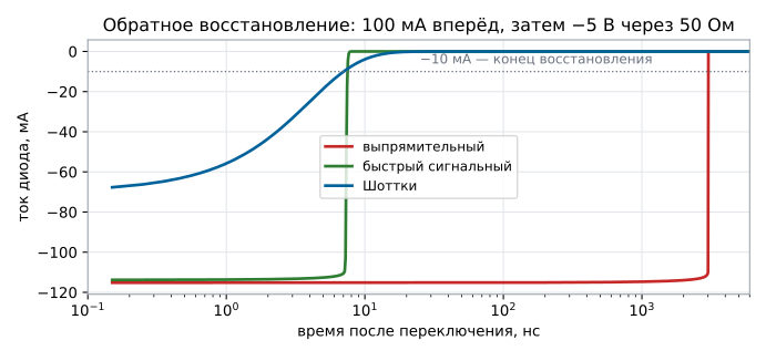
A diode that was carrying forward current does not turn off instantly: the charge in the junction has to be removed, and for a while current flows in reverse. A forward current of about 100 mA, then −5 V through 50 Ω:
| Diode | Peak reverse current | Recovery to −10 mA |
|---|---|---|
| rectifier | 115 mA | 3.02 µs |
| fast signal | 114 mA | 8 ns |
| Schottky | 70 mA | 7 ns |
For three microseconds the rectifier diode conducts in reverse with almost the same current. At 50 Hz this means nothing, but in a 100 kHz converter the period is 10 µs, and 3.02 µs is 30 % of the period with reverse current, losses and spikes. A Schottky has no stored charge at all — only the recharging of the junction capacitance — so in switching circuits the freewheeling diode is a Schottky or a fast recovery diode.
169.5 Junction capacitance: a clamp cuts the bandwidth
An off diode is a capacitor: the depletion layer of the junction acts as a
dielectric, and the higher the reverse voltage, the thicker the layer and the lower the
capacitance — for these models C = C0 / √(1 + U / 1 V). For the Schottky this is 150 pF
at 0 V, 92.1 pF at 1.65 V and 61 pF at 5 V; for the silicon signal diode,
4 pF at 0 V.
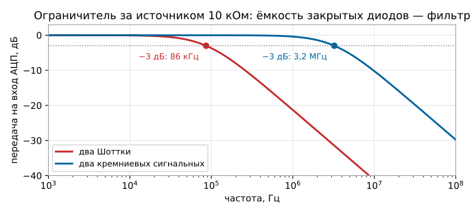
Where you see this: the clamp from section 62 — two diodes from the ADC input to the supply and to ground. A Schottky is good there because it turns on earlier than the pin's internal diodes (0.20 V at 10 mA, 169.1) and takes the injection current. But in normal operation both diodes are off, and their capacitance together with the source resistance forms a filter:
| Clamp | Capacitance at 1.65 V on the input | Bandwidth with a 10 kΩ source |
|---|---|---|
| two Schottky | 2 × 92.1 pF = 184 pF | 86 kHz |
| two silicon signal | 2 × 2.46 pF = 4.9 pF | 3.2 MHz |
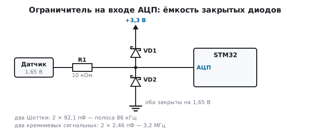
For a battery divider or a temperature sensor 86 kHz is a huge margin, but a Schottky clamp already rolls off a signal of hundreds of kilohertz. On top of that, the capacitance depends on voltage: with a large signal swing the bandwidth "breathes" with it, and that is distortion. For fast lines use clamps with a capacitance of a few picofarads — it is stated in the documentation.
The second cost of a Schottky in a clamp is leakage (169.3). At mid-scale both diodes are reverse-biased equally, their reverse currents are equal and cancel each other: in the model the 1.65 V input does not shift at all. Near the edge of the scale one diode is reverse-biased by almost the whole voltage, the other by only tenths of a volt, and its reverse current is smaller. The difference flows through the source resistance and shifts the input toward mid-scale: behind 10 kΩ an input of 0.3 V at 25 °C shifts by 0.6 mV — less than one code of a 12-bit ADC, and at 85 °C by 30 mV, which is 37 codes; a 0.1 V input shifts by 12 and 112 mV. In the model the leakage hardly depends on voltage; in a real Schottky it grows with reverse voltage, and the difference near the edge of the scale is only larger. For high-impedance inputs use clamps with leakage in nanoamps and check the reverse current at the highest temperature.
169.6 Power OR-ing: USB or battery
The device is powered from USB, and without it from a lithium battery. The simplest circuit is two Schottky diodes into the regulator input, with a 100 mA load:
| Mode | At the regulator input | Current into the battery |
|---|---|---|
| USB present, 25 °C | 4.71 V | 30 µA |
| USB present, 85 °C | 4.81 V | 1.10 mA |
| battery only | 3.41 V | — |
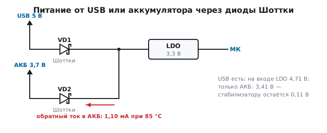
The table shows two drawbacks. The first is reverse current into the battery: with USB connected the battery diode is off, but leakage flows through it, and when warm this is 1.10 mA — 26.5 mAh per day of uncontrolled charging. Charging a lithium battery must be controlled by a charge controller, not by diode leakage. The second is the drop: from a 3.7 V battery the input of a 3.3 V regulator gets 3.41 V, leaving the regulator 0.11 V of headroom (section 55.3), and a discharged battery will not give it even that.
Hence the "ideal diode" circuit — a MOSFET that is on in the forward direction and off in reverse: the drop is milliohms of channel resistance, the leakage is the off-state current of the transistor. It also protects against reverse polarity.
169.7 Pitfalls
The supply after the diode is higher than calculated at light load and lower at heavy load. You assumed "0.7 V", but the drop depends on current: 0.55 V at 1 mA and 0.91 V at 1 A for the same diode.
Readings drift with temperature in a circuit with a diode. −2 mV/°C of forward drop; compensate it or move the diode out of the measurement path.
A battery device drains when warm. Schottky leakage: 30 µA at 25 °C turns into a milliamp at 85 °C.
A diode in a converter runs hot although the forward drop is small. A slow rectifier diode: reverse recovery takes a noticeable fraction of the period.
After adding protection, the sensor signal is rolled off at high frequencies. The capacitance of the off clamp diodes together with the source resistance forms a filter; you need low-capacitance diodes.
The battery is charged from USB bypassing the charge controller. Reverse current of the diode in the OR circuit; you need an "ideal diode" or a switch.
Parallel diodes: one burns, the other stays cold. The negative temperature coefficient of the drop — the current moves into the hot one.
169.8 Summary
- Drop of a silicon rectifier diode: 0.55 V at 1 mA and 0.91 V at 1 A; Schottky — 0.12 and 0.41 V; per decade of current — about 0.11 and 0.08 V.
- Silicon signal diode: −2.4 mV/°C at 100 µA, −2.0 mV/°C at 1 mA.
- Reverse current at 5 V: silicon 2.5 nA → 214 nA, Schottky 30 µA → 1.10 mA (25 → 85 °C).
- Recovery to −10 mA: rectifier 3.02 µs, fast 8 ns, Schottky 7 ns.
- Clamp at an input behind 10 kΩ: two Schottky — 184 pF and 86 kHz bandwidth, silicon signal diodes — 4.9 pF and 3.2 MHz.
- Schottky OR-ing: 4.71 V from USB, 3.41 V from the battery and 1.10 mA of leakage into the battery at 85 °C.
Next: section 170 "Bipolar transistor: operating modes".