 Embedded HandbookApps
17а. The microcontroller as a slave device: I²C and SPI
Usually the microcontroller is the master: it polls sensors. But it often becomes a "sensor" for someone else itself: an expansion board, a module in a rack, a coprocessor next to a Linux board. Then the clock is set by someone else's master, and the main question changes — not "how to send", but "will I manage to answer in time".
This section covers an I²C slave device with a register map (like real sensors) and
the calculation of the response time for SPI. The register map logic (regmap.c) is one and the same
in the firmware and in the bus model on a computer; the interrupt handler for the F407 is built
with the CMSIS headers. The block rules follow the F4 reference manual. The files are in
_verify/slave17a/, checked by _verify/slave17a_check.py.
Terms used in the documentation
Term Meaning slave transmitter / slave receiver a slave that sends / that receives clock stretching the slave holding the clock low NOSTRETCH (clock stretching disable) forbidding clock stretching ADDR, STOPF, AF (slave events) address matched, STOP, the master answered NACK register map, auto-increment pointer a set of addressable registers, a pointer that increments by itself overrun / underrun (OVR, NOSTRETCH = 1) a lost / a repeated byte without stretching dummy byte an empty byte that gives the slave time
17а.1 What a slave looks like from outside: the register map
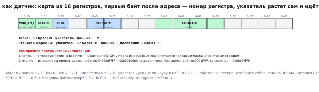
It is most convenient for the master when the slave looks like an ordinary sensor: it has registers, the first byte after the address is the register number, then the pointer increments by itself. Our map of 16 bytes:
| Address | Register | Access |
|---|---|---|
| 0x00 | WHO_AM_I = 0x5A | read |
| 0x01 | STATUS: the number of writes received | read |
| 0x02 | CTRL | read and write |
| 0x04…0x05 | SETPOINT, 16 bits, low byte first | read and write |
| 0x08…0x0B | COUNTER, 32 bits | read |
The master's transactions are the same as for any sensor:
- write:
Saddress+W · pointer · data… ·P; - read:
Saddress+W · pointer ·Sraddress+R · data… (the last one — NACK) ·P.
Two rules without which the slave returns "torn" values:
- Write into a shadow copy, into the working one — on STOP. A two-byte setpoint is written by two events; if the firmware looks in between them, it will see the new low byte with the old high one. So the bytes accumulate in the shadow and are transferred as a whole on STOP.
- Read from a snapshot taken at the address. A counter 0x0000FFFF that stepped over to 0x00010000 in the middle of a read: without a snapshot the master would have got 0x0001FFFF — the high bytes from the new value, the low ones from the old. With a snapshot — exactly 0x0000FFFF.
A check of the logic in the model: the write 0x0F, 0xAA, 0xBB, 0xCC puts 0xAA into 0x0F,
then the pointer wraps around to 0x00 and 0x01 — both "read only", two bytes
are discarded (WHO_AM_I stayed 0x5A); before STOP register 0x0F is still old (0x00), after it 0xAA.
17а.2 Five events of the I²C block
The I²C block catches its address by itself, sets ACK by itself and holds the line by itself if
the program has not managed in time. What is left to the program is events (flags in SR1/SR2):
| Event | When | How to clear |
|---|---|---|
| ADDR | the address matched; TRA in SR2 is the direction |
read SR1, then SR2 |
| RXNE | a byte has been received | read DR |
| TXE | the next byte to transmit is needed | write DR |
| AF | the master answered NACK — it has finished reading | write 0 into the AF bit |
| STOPF | the master finished the transaction | read SR1, then write CR1 |
The handler for the F407 translates the flags into calls of the logic:
void I2C1_EV_IRQHandler(void)
{
    uint32_t sr1 = I2C1->SR1;
    if (sr1 & I2C_SR1_ADDR) {
        uint32_t sr2 = I2C1->SR2;                                          /* SR1, затем SR2 — ADDR сброшен */
        int read = (sr2 & I2C_SR2_TRA) != 0;
        rm_on_addr(&rm, read);
        if (read)
            I2C1->DR = rm_on_tx(&rm);                                      /* первый байт — сразу, пока SCL держится */
        return;
    }
    if (sr1 & I2C_SR1_RXNE)
        rm_on_rx(&rm, (uint8_t)I2C1->DR);
    if ((sr1 & I2C_SR1_TXE) && !(sr1 & I2C_SR1_AF))
        I2C1->DR = rm_on_tx(&rm);
    if (sr1 & I2C_SR1_STOPF) {
        I2C1->CR1 |= I2C_CR1_ACK;                                          /* SR1 уже прочитан; запись CR1 сбрасывает STOPF */
        rm_on_stop(&rm);
    }
}
The slave initialisation and the error handler — from the same file:
void i2c_slave_init(void)
{
    rm_init(&rm);
    RCC->AHB1ENR |= RCC_AHB1ENR_GPIOBEN;
    RCC->APB1ENR |= RCC_APB1ENR_I2C1EN;
    GPIOB->MODER = (GPIOB->MODER & ~(0xFu << 12)) | (0xAu << 12);        /* PB6, PB7 — альтернативная функция */
    GPIOB->OTYPER |= (1u << 6) | (1u << 7);                                /* открытый сток */
    GPIOB->AFR[0] = (GPIOB->AFR[0] & ~(0xFFu << 24)) | (0x44u << 24);      /* AF4 = I2C1 */
    I2C1->CR2 = 42;                                                        /* частота APB1, МГц */
    I2C1->OAR1 = 0x42u << 1;                                               /* 7-битный адрес 0x42 */
    I2C1->CR2 |= I2C_CR2_ITEVTEN | I2C_CR2_ITBUFEN | I2C_CR2_ITERREN;
    I2C1->CR1 = I2C_CR1_PE;
    I2C1->CR1 |= I2C_CR1_ACK;                                              /* ACK ставится только при PE = 1 */
    NVIC_EnableIRQ(I2C1_EV_IRQn);
    NVIC_EnableIRQ(I2C1_ER_IRQn);
}

void I2C1_ER_IRQHandler(void)
{
    if (I2C1->SR1 & I2C_SR1_AF) {                                          /* ведущий ответил NACK — чтение закончено */
        I2C1->SR1 = ~I2C_SR1_AF;
        rm_on_nack(&rm);
    }
}
Built with arm-none-eabi-gcc -Os: the initialisation and both handlers are 268 bytes,
the register map logic 260.
An extra byte when reading. The block asks for the next byte (TXE) when the previous one
has only begun to go out — the slave does not know that the master will stop on it. So
there is always one byte more in DR than has been read, and the pointer runs
ahead. On AF it is moved back by one — otherwise the next "continued read"
will skip a register.
17а.3 Clock stretching: the bus waits for the program
While ADDR is not cleared, the block holds SCL low — the master waits. Likewise, if
by the end of the next byte the program has not read DR (or has not written it when
transmitting), the block sets BTF and holds SCL. So the margin is one byte with ACK:
9 bits, 90 µs at 100 kHz and 22.5 µs at 400 kHz.
The model: the master writes the setpoint 2500 (address, pointer 0x04, two bytes) and reads the counter 0x12345678 (pointer 0x08, repeated START, 4 bytes). The processor responds to each event after L µs:
| Bus | L | Write | of which held by the slave | Read | held |
|---|---|---|---|---|---|
| 100 kHz | 2 µs | 382 µs | 2 | 664 µs | 4 |
| 100 kHz | 100 µs | 500 µs | 120 | 890 µs | 230 |
| 400 kHz | 2 µs | 97 µs | 2 | 169 µs | 4 |
| 400 kHz | 30 µs | 140 µs | 45 | 252.5 µs | 87.5 |
| 400 kHz | 100 µs | 350 µs | 255 | 672.5 µs | 507.5 |
The data is correct in all rows: the setpoint 2500, the counter 0x12345678. The price of a slow slave is bus time: at 400 kHz with L = 100 µs a write takes 350 µs instead of 95. As long as L is less than 22.5 µs, only the ADDR event holds the bus (L per address).
17а.4 NOSTRETCH: the bus does not wait — the data gets corrupted
Not every master supports a stretched clock. Then the slave is given
NOSTRETCH = 1, and being late turns into an OVR error:
- receive:
DRnot read by the end of the next byte — the new byte is lost; - transmit:
DRnot written in time — the same byte goes out twice.
The same model without stretching:
| Bus | L | Setpoint after the write | Counter read as |
|---|---|---|---|
| 100 kHz | 2…30 µs | 2500 — correct | 0x345678FF |
| 100 kHz | 100 µs | 777 (0x0309) | 0x7878FFFF |
| 400 kHz | 2…10 µs | 2500 — correct | 0x345678FF |
| 400 kHz | 30 µs | 777 (0x0309) | 0x7878FFFF |
| 400 kHz | 100 µs | 1000 — the old one | 0xFFFFFFFF |
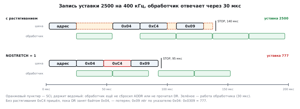
How 777 came about: the byte 0xC4 was lost, 0x09 was written at pointer 0x04 — into the low byte; the high one stayed 0x03. 0x0309 = 777 instead of 2500 — without a single error signal to the master.
The counter gets corrupted even with L = 2 µs: the first byte of a read must go out right after the
address ACK, but the ADDR handler has not yet managed to write DR — whatever was
there (0xFF) goes out, and all the bytes shift. Without stretching the first byte is put
into DR in advance, before the address arrives, and the rest via DMA.
17а.5 An SPI slave: the answer is needed before the question
SPI has no stretching at all: the clock runs as long as the master provides it, and the reply bits
are shifted out simultaneously with the command bits. The manual requires the slave's DR
to be ready before the first clock edge; the clock frequency for a slave is no higher than
fPCLK/2.
If the master sends a command and expects the answer immediately, the slave has only half a period of SCK between the last bit of the command and the first bit of the answer. With one empty byte — eight more periods. In clock cycles of a 168 MHz core:
| SCK | Byte | Without an empty byte | With one empty byte |
|---|---|---|---|
| 1 MHz | 8000 ns | 84 cycles | 1428 cycles |
| 4 MHz | 2000 ns | 21 cycles | 357 cycles |
| 10 MHz | 800 ns | 8.4 cycles | 142.8 cycles |
| 21 MHz | 381 ns | 4 cycles | 68 cycles |
| 42 MHz | 190 ns | 2 cycles | 34 cycles |
Without an empty byte what remains is from 84 cycles at 1 MHz to 2 at 42 MHz — and in this time
you must enter the interrupt, read the command, choose the answer and write DR. Already
from a few megahertz this is impossible. Hence how SPI slaves are designed:
- an empty byte (or several) between the command and the answer — the protocol gives time;
- the answer in advance: the slave puts the "current state" into a DMA buffer beforehand, and the master reads it straight away, without a command;
- NSS as a frame: the falling edge of NSS is a "transaction start" interrupt, the rising edge is the "end"; the command is parsed after the frame, not in the middle of it.
SPI on the F4 has no "failed to write in time" flag (UDR exists only in I2S mode): a slave
that is late with DR will simply send the wrong bits, and only the master can find out about it —
by a checksum.
17а.6 Pitfalls
The setpoint got a strange value without any errors. NOSTRETCH = 1 and
a slow handler: a byte was lost, the others were written to the wrong place. Allow
stretching or receive via DMA.
The first byte read is 0xFF or "the previous one". Without stretching DR was not
filled before the first byte. Put it there in advance.
Every second read skips a register. The pointer was not moved back on AF: the extra byte requested by TXE "ate" a register.
A multi-byte value is sometimes "torn". There is no snapshot on reading or shadow on writing.
The slave does not answer its address. ACK in CR1 is cleared by hardware when PE = 0:
written before the block is enabled, it is lost. Set it after PE = 1.
ADDR does not clear. Only SR1 was read — SR2 is needed too. And the other way round:
an extra read of SR2 without checking ADDR clears an ADDR that arrived between
the two reads.
An SPI slave returns garbage at a high frequency. An answer in the same byte as the command is physically impossible — an empty byte or DMA with a ready answer is needed.
17а.7 Summary
- A slave as a sensor: the first byte is the pointer, then auto-increment; writing goes into the shadow until STOP, reading from a snapshot. Without this 0x0000FFFF reads as 0x0001FFFF.
- Five I²C events: ADDR (SR1 → SR2), RXNE, TXE, AF, STOPF (SR1 → write CR1).
- With stretching the data is correct at any slowness, and bus time pays for it: at 400 kHz with a 100 µs response a write takes 350 µs instead of 95.
- Without stretching the margin is 9 bits (22.5 µs at 400 kHz); be late and a byte is lost or repeated: the setpoint 2500 silently turns into 777.
- An SPI slave cannot answer in the same byte: without an empty byte at 10 MHz 8 cycles remain, with an empty one 143.
Full sources
i2c_slave_f4.c — the interrupt handlers of an I²C slave on the STM32F4.
/* Раздел 17а: ведомый I²C на STM32F4 (I2C1, PB6 = SCL, PB7 = SDA, адрес 0x42) — обработчики прерываний.
 * Порядок сброса флагов — по RM0090: ADDR — чтение SR1, затем SR2; STOPF — чтение SR1, затем запись CR1;
 * AF — запись 0 в бит AF. Сама логика — в regmap.c, одинаковая для прошивки и модели на компьютере. */
#include "stm32f4xx.h"
#include "regmap.h"

static regmap_t rm;

void i2c_slave_init(void)
{
    rm_init(&rm);
    RCC->AHB1ENR |= RCC_AHB1ENR_GPIOBEN;
    RCC->APB1ENR |= RCC_APB1ENR_I2C1EN;
    GPIOB->MODER = (GPIOB->MODER & ~(0xFu << 12)) | (0xAu << 12);        /* PB6, PB7 — альтернативная функция */
    GPIOB->OTYPER |= (1u << 6) | (1u << 7);                                /* открытый сток */
    GPIOB->AFR[0] = (GPIOB->AFR[0] & ~(0xFFu << 24)) | (0x44u << 24);      /* AF4 = I2C1 */
    I2C1->CR2 = 42;                                                        /* частота APB1, МГц */
    I2C1->OAR1 = 0x42u << 1;                                               /* 7-битный адрес 0x42 */
    I2C1->CR2 |= I2C_CR2_ITEVTEN | I2C_CR2_ITBUFEN | I2C_CR2_ITERREN;
    I2C1->CR1 = I2C_CR1_PE;
    I2C1->CR1 |= I2C_CR1_ACK;                                              /* ACK ставится только при PE = 1 */
    NVIC_EnableIRQ(I2C1_EV_IRQn);
    NVIC_EnableIRQ(I2C1_ER_IRQn);
}

void I2C1_EV_IRQHandler(void)
{
    uint32_t sr1 = I2C1->SR1;
    if (sr1 & I2C_SR1_ADDR) {
        uint32_t sr2 = I2C1->SR2;                                          /* SR1, затем SR2 — ADDR сброшен */
        int read = (sr2 & I2C_SR2_TRA) != 0;
        rm_on_addr(&rm, read);
        if (read)
            I2C1->DR = rm_on_tx(&rm);                                      /* первый байт — сразу, пока SCL держится */
        return;
    }
    if (sr1 & I2C_SR1_RXNE)
        rm_on_rx(&rm, (uint8_t)I2C1->DR);
    if ((sr1 & I2C_SR1_TXE) && !(sr1 & I2C_SR1_AF))
        I2C1->DR = rm_on_tx(&rm);
    if (sr1 & I2C_SR1_STOPF) {
        I2C1->CR1 |= I2C_CR1_ACK;                                          /* SR1 уже прочитан; запись CR1 сбрасывает STOPF */
        rm_on_stop(&rm);
    }
}

void I2C1_ER_IRQHandler(void)
{
    if (I2C1->SR1 & I2C_SR1_AF) {                                          /* ведущий ответил NACK — чтение закончено */
        I2C1->SR1 = ~I2C_SR1_AF;
        rm_on_nack(&rm);
    }
}

uint16_t app_setpoint(void)
{
    return rm_setpoint(&rm);
}
Next: section 18 "SPI" — an interface that is much simpler and works an order of magnitude faster.