 Embedded HandbookApps
94б. Flipper Zero inside: STM32WB55, FreeRTOS and 433 MHz radio, NFC, RFID and IR in one firmware
Sections 93 and 94а covered one radio each: a LoRa module on SPI and an NFC tag on I²C. Flipper Zero is a pocket device with five such paths: a 300–928 MHz transceiver, an NFC reader, a 125 kHz tag reader, an IR port and an iButton contact. All of this is served by a single STM32WB55, and the device's firmware is open. This is a rare case where you can read from start to finish how a production device on STM32 with an RTOS, external programs and several radios at once is built.
Here: what is connected to what, how the device's OS on top of FreeRTOS is built and how pulse durations turn into the codes of a remote, a tag and a key fob. Three firmware decoders are built on a PC unchanged and run on generated frames with jitter: you can see where each one stops recognizing the signal.
This section is for learning and for protection. Receiving and analysing the air and your own tags is fine. Transmitting other people's codes, copying other people's key fobs and access cards without the owner's permission is not; how to do that is not described here. The firmware itself does not let you transmit outside the allowed bands (94б.4).
Sources: the firmware source — github.com/flipperdevices/flipperzero-firmware
(commit 7f0b6e1); below are only short fragments with paths.
Microcontroller — the description of the Keil STM32WBxx_DFP pack (core frequencies),
the datasheet DS11929 and the reference manual RM0434 from the same pack, the
STM32CubeMX database (memory size of STM32WB55RG). The decoders are built with gcc in the image
stm-sys:1 with furi stubs, the sizes with arm-none-eabi-gcc in stm-arm:1; directory _verify/flip94b.
The firmware as a whole is not built: 10 submodules (FreeRTOS, HAL, the BLE stack
and others) were not downloaded for this section, and the fbt build tool downloads its own set
of compilers from the network. STM32WB registers — appendix A17.
License: GPL-3.0.
Terms used in the documentation
Term Meaning Sub-GHz radio below 1 GHz: 315, 433, 868 MHz te, te_short, te_long, te_delta the frame time step, short and long pulse, tolerance Static, Dynamic (protocol type) fixed code and rolling code preamble, guard time the lead-in of a frame and the pause between frames mark, space an IR burst and a pause Manchester Manchester code: a bit is a transition in the middle of the bit period record, pubsub a record (a named shared object) and publish/subscribe messaging FAP, .fapan external program from the memory card CPU2, coprocessor (copro) the second core, a Cortex-M0+ with the radio stack region provisioning the table of allowed transmit bands for a country
94б.1 What is inside
The heart of the device is the STM32WB55RG (that is how it is named in
.vscode/example/launch.json): VFQFPN68 package, 1 MB Flash, 256 KB RAM
(STM32CubeMX database). The WB55 has two cores: a Cortex-M4 at 64 MHz for programs
and a Cortex-M0+ at 32 MHz for the radio (description of the STM32WBxx_DFP pack). The
2.4 GHz radio for Bluetooth LE is inside the chip itself.
Everything else is connected externally. Two SPI buses: SPI1 ("bus R" in
furi_hal_spi_config.c) goes to the radio chips, SPI2 ("bus D") goes to the
display and the memory card:
| What | Chip | How it is connected | File |
|---|---|---|---|
| radio 300–928 MHz | CC1101 | SPI1, CS on PD0, GDO0 output on PA1 → TIM2 | lib/drivers/cc1101.c |
| NFC 13.56 MHz | ST25R3916 | SPI1, CS on PE4, interrupt on PA2 | lib/drivers/st25r3916.c |
| display 128×64 | ST7567 | SPI2, CS on PC11 | lib/u8g2/u8g2_glue.c |
| microSD card | — | SPI2, CS on PC12, FatFS | targets/f7/fatfs |
| RFID 125 kHz | — | TIM1 carrier on PB13, signal through COMP1 → TIM2 | furi_hal_rfid.c |
| IR port | — | receive PA0 → TIM2, transmit PB9 | furi_hal_infrared.c |
| iButton | — | 1-Wire on PB14 | lib/one_wire |
The pins come from targets/f7/furi_hal/furi_hal_resources.h.
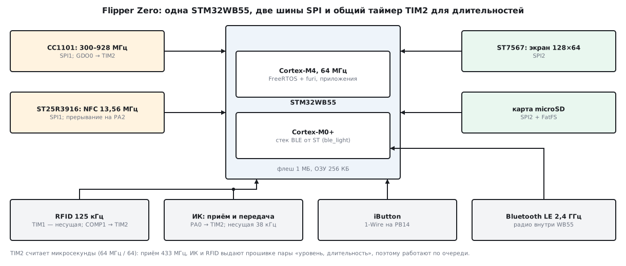
Three of the five paths — 433 MHz, IR and RFID — come down to the same thing:
timer TIM2 in capture mode measures pulse durations in
microseconds. The prescaler is 64 - 1 everywhere with a 64 MHz clock
(CPU_CLOCK_PLL_HZ in furi_hal_clock.c). The protocol decoders see
only "level, duration" pairs — which is why you can build and
test them on a PC without the device (94б.4–94б.6).
94б.2 Two cores, memory and FreeRTOS
The second core. The Bluetooth stack runs on the Cortex-M0+; its firmware is
a binary file from ST. fbt_options.py selects the light stack:
COPRO_STACK_BIN = "stm32wb5x_BLE_Stack_light_fw.bin"
The stack lives in the protected Flash area of the second core. According to RM0434, the
SFSA field of the FLASH_SFR register is the number of the first 4-kilobyte page of this
area; only CPU2 can write this register, and a write by the M4 core to the
protected area is ignored with a bus error. That is exactly how the firmware
computes where its own space ends: SFSA × 4096 + the Flash start
(furi_hal_flash_get_free_end_address in furi_hal_flash.c).
M4 core memory. The linker script targets/f7/stm32wb55xx_flash.ld
takes Flash from 0x08000000 with length 1024K, SRAM1 from 0x20000008 with length
0x2FFF8 (192 KB minus 8 bytes) and 10K each in SRAM2a (0x20030000) and
SRAM2b (0x20038000). The script does not touch the rest of SRAM2.
FreeRTOS. The settings are in targets/f7/inc/FreeRTOSConfig.h: preemption
enabled, 1000 Hz tick, 32 priority levels, task names up to 32 characters.
The heap is all free RAM between __heap_start__ and __heap_end__;
the loader also takes the sections of programs from the card out of the heap (aligned_malloc
in elf_file.c). How the FreeRTOS kernel is built —
section 24.
94б.3 furi: an OS on top of FreeRTOS and programs from the card
Programs do not call FreeRTOS directly — there is the furi layer between them
(furi/core). Its parts:
- threads
furi_thread_*— FreeRTOS tasks with a name, a stack and a return code; - queues
furi_message_queue_*— a message queue of fixed size; - records
furi_record_*— shared objects by name: the display (gui), power, storage.furi_record_openwaits until the record is created: inside it is a wait on the flagFURI_RECORD_FLAG_READYwith no timeout; - pubsub
furi_pubsub_*— subscription to events: a service publishes, subscribers receive; - event loop
furi_event_loop_*— one thread waits on a queue, a semaphore, a mutex, a byte stream and a timer at once and calls the handler of whichever is ready.
A program is described by an application.fam file. An example from
applications/examples/example_thermo (a DS18B20 thermometer on 1-Wire):
App(
    appid="example_thermo",
    name="Example: Thermometer",
    apptype=FlipperAppType.EXTERNAL,
    entry_point="example_thermo_main",
    requires=["gui"],
    stack_size=1 * 1024,
    fap_icon="example_thermo_10px.png",
    fap_category="Examples",
)
EXTERNAL means: the program is built as a separate .fap file and
loaded from the memory card. It is an ELF with relocations
(targets/f7/application_ext.ld places the code at address 0) and a manifest in
the .fapmeta section: API version, board code, name, stack size. The loader
(lib/flipper_application) refuses if the program's API is older or
newer than the firmware's, or the board is different. What a program may call
is listed in targets/f7/api_symbols.csv: API version 88.2, 3537
functions, of which 2451 are public (status +), 1086 are private (-).
The thermometer itself is a typical program: a sensor reading thread, a queue of
button events for 8 messages, the gui and power records.
94б.4 433 MHz: CC1101 and the Princeton decoder
Frequencies. The firmware accepts frequencies in three windows —
299999755…348000335, 386999938…464000000 and
778999847…928000000 Hz (furi_hal_subghz_is_frequency_valid).
The CC1101 crystal is 26 MHz (CC1101_QUARTZ): the frequency is written to the registers
as value · 65536 / 26000000.
Transmit only in your own band. When the frequency changes, the firmware looks it up in
the region table (furi_hal_region.c). For the "EU" region (Europe and
Russia) there are two bands: 433.05–434.79 and 868.15–868.55 MHz. Outside the table
the "receive only" mode is turned on, and transmission refuses:
bool furi_hal_subghz_tx(void) {
    if(furi_hal_subghz.regulation != SubGhzRegulationTxRx) return false;
Reception. The CC1101 demodulator output (GDO0) is wired to TIM2. A falling edge
records the duration of the high level, a rising edge that of the low level, and both go
to the handler as a "level, duration" pair (furi_hal_subghz_capture_ISR).
The capture input filter discards glitches shorter than 16 µs — this
is written right in the comment to the TIM2 setup.
How a decoder recognizes a remote. The firmware has 53 protocols
(lib/subghz/protocols/protocol_items.c); the receiver (lib/subghz/receiver.c)
passes every duration to the decoders of all protocols that passed the filter, and
each one decides for itself whether it looks like its frame. The simplest is
Princeton, the fixed 24-bit code of cheap remotes. Its constants
(lib/subghz/protocols/princeton.c):
static const SubGhzBlockConst subghz_protocol_princeton_const = {
    .te_short = 390,
    .te_long = 1170,
    .te_delta = 300,
    .min_count_bit_for_found = 24,
};
A bit is a "high, low" pair: 1 is long and short, 0 is short
and long. The decision for each pair:
            if((DURATION_DIFF(instance->decoder.te_last, subghz_protocol_princeton_const.te_short) <
                subghz_protocol_princeton_const.te_delta) &&
               (DURATION_DIFF(duration, subghz_protocol_princeton_const.te_long) <
                subghz_protocol_princeton_const.te_delta * 3)) {
                subghz_protocol_blocks_add_bit(&instance->decoder, 0);
A short pulse is accepted within ±300 µs, a long one within ±900. The start is found by a pause of 390 · 36 = 14040 µs with a tolerance of 300 · 36; a low level no shorter than 2 · 1170 µs ends the frame. The pause between frames is 30 steps by default. And the main thing: the decoder reports a code only if two frames in a row match.
Experiment. The feed function is cut out of princeton.c unchanged and
built on a PC. The frames carry the code 0xA1B2C3, step 390 µs:
| Condition | Result |
|---|---|
| 4 frames in a row | 3 detections: data 0xA1B2C3, serial 0xA1B2C, button 0x3, step 390, pause 30 steps |
| 1 frame | 0 detections |
| 2 frames | 1 detection |
| step without jitter | recognized from 110 to 680 µs |
| jitter ±299 µs | 1000 of 1000 |
| jitter ±300 µs | 983 of 1000 |
| jitter ±350 µs | 1 of 1000 |
| jitter ±400 µs | 0 of 1000 |
The serial number and the button are just the upper 20 and the lower 4 bits. The decoder does not know the remote's step in advance: it computes it from the sum of the frame's durations. The tolerances are wide: a short pulse may differ from 390 µs by 77 % (300 µs). Random matches with noise are cut off by the rule of two identical frames.
Rolling code. A fixed code is the same at every press: whoever
heard it knows it forever. A rolling code, for example KeeLoq
(keeloq.c, 64 bits per frame, type Dynamic), has an encrypted part
with a counter (Cnt in the output). The decoder shows the open part —
the serial number and the button — and decrypts the encrypted part only with the manufacturer's key
from a separate key store. For your own device the conclusion is simple: a fixed code
is fine for a doorbell, but not for a lock.
94б.5 IR port: the NEC decoder
The NEC protocol is covered in section 198о: there the step is 562.5 µs, with its own
decoder and a 25 % tolerance. Flipper uses rounded times and
fixed tolerances (lib/infrared/encoder_decoder/nec/infrared_protocol_nec_i.h):
| What | Mark | Space | Tolerance |
|---|---|---|---|
| preamble | 9000 µs | 4500 µs | ±200 µs |
| bit 1 | 560 µs | 1690 µs | ±120 µs |
| bit 0 | 560 µs | 560 µs | ±120 µs |
| repeat | 9000 µs | 2250 µs | ±200 µs |
The transmitter carrier is 38000 Hz, duty cycle 0.33
(INFRARED_COMMON_CARRIER_FREQUENCY, INFRARED_COMMON_DUTY_CYCLE).
The common decoder infrared_common_decoder.c is shared by all protocols: it
looks for the preamble and slices the frame into bits by a timing table, while the protocol file
sets the times and the bit parsing. If the second half of the
frame is not the inverse of the address and command, it is treated as NECext with a 16-bit
address and command. The firmware has eight protocol families: NEC, Samsung, RC5, RC6,
SIRC, Kaseikyo, RCA, Pioneer.
Experiment. The encoder and decoder are built from the firmware files unchanged.
| Frame | Result |
|---|---|
| firmware encoder: address 0x04, command 0x08 | 68 durations; decoder: NEC, 0x04, 0x08 |
| times 562/1688 µs (as in 198о) | NEC, 0x04, 0x08 |
| address bytes 0x34 and 0x12 | NECext, address 0x1234, command 0xF708 |
| frame and repeat code | 1 frame, 1 repeat |
| marks longer by 119 µs, spaces shorter | recognized |
| marks longer by 120 µs | not recognized |
| jitter of every duration ±119 µs | 1000 of 1000 |
| jitter ±120 µs | 606 of 1000 |
| jitter ±150 µs | 0 of 1000 |
The edge sits exactly at the tolerance: the comparison is strict, MATCH_TIMING lets through
only a difference of less than 120 µs. Section 198о shows how a receiver
stretches marks by 100 µs; with Flipper such a receiver still passes,
but the margin is 20 µs.
94б.6 RFID 125 kHz and iButton
How a tag is read. TIM1 drives a 125 kHz carrier into the antenna
(furi_hal_rfid_tim_read_start(125000, 0.5) in lfrfid_worker_modes.c).
The signal from the antenna, through the board's analog circuit (it is not in the sources),
comes to the COMP1 comparator: the threshold is half of VREFINT, the hysteresis is
large, and the comparator output is routed inside the chip to the capture input of
TIM2. As with 433 MHz, from here on there are only durations: the decoders
receive first the duration of the burst, then that of the pause. The firmware has 24 tag
protocols (lfrfid_protocols.c).
EM4100 is the simplest tag, read-only. A frame is 64 bits:
9 header ones, 10 rows of 4 data bits and a parity bit, 4 column
parity bits and a stop 0. The data is 5 bytes. The code is Manchester;
a bit lasts 64 carrier periods, a half-bit 32 periods, 256 µs. The decoder
windows (protocol_em4100.c):
#define EM_READ_SHORT_TIME_BASE  (256)
#define EM_READ_LONG_TIME_BASE   (512)
#define EM_READ_JITTER_TIME_BASE (100)
A short pulse is strictly between 156 and 356 µs, a long one between 412 and 612 µs. A frame is accepted only if the header, the stop bit, all 10 row parities and 4 column parities match, and the next 9 bits are a header again.
Experiment. protocol_em4100.c and manchester_decoder.c are built
unchanged. The firmware encoder for the data 12 34 56 78 9A produced the frame
0xFF8CA64A98F8CA96 and a half-bit of 32 periods; assembling the frame ourselves by the format
above gave the same. Then frames at 256 µs per half-bit go into the decoder:
| Condition | Result |
|---|---|
| 6 frames without jitter | 4 correct reads, the first after 191 bits |
| jitter ±99 µs | 4 reads from 6 frames in 1000 of 1000 |
| jitter ±100 µs | in 12 of 1000 |
| jitter ±120 µs | in 0 of 1000 |
| one data bit inverted | not a single read |
The first read arrives after almost three frames: the decoder waits for the header of
the next frame. One read is not enough for the device: lfrfid_worker_modes.c
accepts a tag when, after the first read, as many more matched
as the protocol's validate_count requires — for EM4100 that is 3. In total four
identical reads — exactly what 6 frames gave.
iButton is a key tablet on 1-Wire. The bus timings are in
lib/one_wire/one_wire_host.c: for standard speed, a reset pulse of
480 µs, a presence check 70 µs later, then another 410 µs. The same
library also reads the DS18B20 sensor in the example_thermo example from 94б.3;
the DS18B20 and its bus are in section 96.
Decoder size. For Cortex-M4 with -Os (arm-none-eabi-gcc):
| File | Code, bytes |
|---|---|
infrared_common_decoder.c + infrared_decoder_nec.c |
1066 + 346 |
feed from princeton.c + decoder.c |
376 + 94 |
protocol_em4100.c (with the encoder) + manchester_decoder.c |
1102 + 64 |
A decoder is hundreds of bytes: NEC together with the common decoder is 1412 bytes, 0.13 % of 1 MB of Flash.
94б.7 Pitfalls
- Two radios do not work at the same time. There is one TIM2: it measures 433 MHz, IR and RFID, and RFID also transmits with it during emulation. TIM1 is shared by the RFID carrier, IR transmission and iButton. Hence the structure of the programs: one radio function at a time.
- The NFC interrupt on an RFID pin. In
furi_hal_resources.hNFC_IRQ_PinisRFID_PULL_Pin, PA2. One pin for two paths is one more reason to use them one at a time. - One Princeton frame gives zero codes. The decoder waits for two identical frames in a row. If your own transmitter sends a frame only once, Flipper will not show it, and on the receiving side it looks like it "does not catch anything".
- A remote step outside 110–680 µs. With a 100 µs step, a pause of 30 steps is 3000 µs, while the preamble window starts at 14040 − 10800 = 3240 µs. With a 690 µs step, a short pulse differs from 390 by 300 µs — that is already outside the tolerance. The decoder stays silent even though the signal is strong.
- The strict tolerance edge. ±119 µs — everything accepted, ±120 — 606 frames out of 1000 for NEC; for EM4100 ±99 and ±100 give 1000 and 12. A receiver that consistently stretches an IR mark by 120 µs will not yield a single frame.
- Transmission "disappeared". On a frequency outside the region table the firmware
switches to "receive only", and
furi_hal_subghz_txreturnsfalse. This is not a fault but the band table. - A program from the card does not start. The
.fapmanifest carries the API version: if the major number does not match the firmware's, the loader refuses. After a firmware update, the program is rebuilt. - The firmware cannot be built without the network. The submodules (FreeRTOS, HAL, BLE stack)
are empty in a downloaded copy, and
fbtdownloads its own set of compilers.
94б.8 Summary
- STM32WB55RG: Cortex-M4 at 64 MHz for programs and Cortex-M0+ at 32 MHz with the BLE stack; 1 MB Flash, 256 KB RAM, the application takes 192 KB of SRAM1 and 10 KB each of SRAM2a and SRAM2b.
- Outside: CC1101 and ST25R3916 on SPI1, the ST7567 128×64 display and microSD on SPI2; RFID, IR and 433 MHz are measured by TIM2 with a 1 µs step.
- furi on top of FreeRTOS (1000 Hz tick, 32 priorities): threads, queues,
records, pubsub, event loop;
.fapprograms from the card, API 88.2 — 2451 public functions. - Princeton: step 390 µs, tolerance ±300/±900, two identical frames; recognizes steps of 110–680 µs and jitter up to ±299 µs.
- NEC in Flipper: 560/1690 µs, tolerance ±120 µs, strict — ±119 all, ±120 — 606 of 1000.
- EM4100: 64-bit frame, half-bit 256 µs, window ±100 µs; the tag is accepted after 4 identical reads.
- Transmission only in the region's bands; for "EU" these are 433.05–434.79 and 868.15–868.55 MHz.
Next: section 95 "How to connect sensors: power, pull-ups, levels, wires".