 Embedded HandbookApps
150. ESP32 as a platform: chip, module, memory, pins, boot
Everything in the book up to this part is about STM32. Part XVIII is about the second microcontroller that everyone runs into once they build devices with Wi-Fi and Bluetooth: the ESP32. It is not "one more series" but a different world: two cores of a different architecture, a program in external flash memory read through a cache, a radio on the die, its own operating system in the box and its own build system. Everything that the earlier parts said about registers and HAL has to be learned again here — but the principles are the same, and this section shows exactly where they match and where they do not.
There is no board for the experiments, and you do not need one: ESP-IDF ships with
the QEMU emulator for ESP32. Every program in this part is built by
the real Espressif compiler and run in the emulator in the container
espressif/idf:v5.4.1; the numbers in the text come from these runs and from the headers of
ESP-IDF itself (_verify/esp150/). What the emulator cannot do — radio, ADC,
sleep — is checked by building, by calculation or with a model, and the text says so explicitly.
Terms used in the documentation
Term Meaning SoC (system on chip) cores, memory, radio and peripherals in one package module (ESP32-WROOM-32) chip, flash memory, crystal and antenna on one small board under a shield development kit (DevKit) a development board: module plus USB-UART, regulator and buttons Xtensa LX6, dual core the core architecture and the two cores: PRO_CPU and APP_CPU IRAM, DRAM internal instruction RAM and data RAM IROM, DROM cache windows through which code and constants in flash memory are seen RTC fast / slow memory memory of the low-power domain, survives deep sleep strapping pins pins whose level at reset selects the boot mode eFuse one-time programmable bits: revision, MAC, protection first / second stage bootloader the bootloader in the chip ROM and the ESP-IDF bootloader in flash partition table the table of flash memory partitions app image, segment the application image and its segments by memory region chip revision revision of the die (v0.0 … v3.x)
150.1 Chip, module, board
The ESP32 is sold in three forms, and you must not mix them up. The chip is a QFN package with two Xtensa LX6 cores, RAM, radio and peripherals, but, as a rule, without flash memory (ESP32-D0WD): the program is stored outside, in an SPI flash chip. The exceptions are variants with flash memory in the package (D2WD, U4WDH) and the PICO parts, which already contain flash memory and a crystal. The module ESP32-WROOM-32 is the chip, 4 MB of flash memory, a 40 MHz crystal and a PCB antenna under a metal shield; this is what goes on a product board. The development board (DevKit) is the module plus a USB-UART bridge, a 3.3 V regulator, the EN and BOOT buttons and pin headers; this is where you start.
The program finds out what it runs on through esp_chip_info:
    esp_chip_info(&ci);
    esp_flash_get_size(NULL, &flash);
    printf("chip: model %d, cores %d, revision v%d.%d, wifi %d, bt %d, ble %d\n", ci.model, ci.cores,
           ci.revision / 100, ci.revision % 100, !!(ci.features & CHIP_FEATURE_WIFI_BGN),
           !!(ci.features & CHIP_FEATURE_BT), !!(ci.features & CHIP_FEATURE_BLE));
chip: model 1, cores 2, revision v0.0, wifi 1, bt 1, ble 1
flash: 2048 KiB, cpu: 160 MHz
Model 1 is CHIP_ESP32 (the S2 is 2, the S3 is 9, the C3 is 5, the C6 is 13:
the family is large and mixed, and this part is about the classic ESP32).
The revision is v0.0 because this is the emulator; real chips have v1.0 and v3.x, and
the revision is read from eFuse. The flash memory size is the one written into
the image header at build time, not the one on the module: by default
ESP-IDF writes 2 MB, and on a module with 4 MB half of it stays invisible until
you fix it in menuconfig. The default core frequency is 160 MHz, the limit is
240.
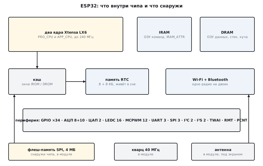
150.2 How many of each: numbers from the headers
ESP-IDF describes all capabilities of the chip in one header, soc_caps.h,
and it is better to take the figures from there than from memory:
| What | How many | Header |
|---|---|---|
| cores | 2 | SOC_CPU_CORES_NUM |
| GPIO numbers | 0–39, without 24, 28–31; 34–39 input only; GPIO20 is not bonded out in every package | SOC_GPIO_VALID_*_MASK |
| ADC | 2 units: 8 + 10 channels | SOC_ADC_CHANNEL_NUM |
| DAC | 2 channels of 8 bits | SOC_DAC_CHAN_NUM, SOC_DAC_RESOLUTION |
| LEDC PWM | 8 channels in each of two speed modes, timer up to 20 bits | SOC_LEDC_* |
| MCPWM PWM | 2 units × 3 operators × 2 generators | SOC_MCPWM_* |
| timers | 2 groups × 2, 64-bit counter | SOC_TIMER_GROUP_* |
| UART / SPI / I²C / I²S | 3 / 3 / 2 / 2 | SOC_*_NUM |
| TWAI (CAN) | 1 | SOC_TWAI_CONTROLLER_NUM |
| RMT / PCNT | 8 channels each | SOC_RMT_*, SOC_PCNT_* |
| touch inputs | 10 | SOC_TOUCH_SENSOR_NUM |
| Wi-Fi, Bluetooth, Ethernet MAC, SD host, ULP | present | SOC_*_SUPPORTED |
Of the three SPI, two are free for your own devices — SPI2_HOST and SPI3_HOST
(on the ESP32 their old names are HSPI_HOST and VSPI_HOST). The third, SPI1, serves
the program flash memory: its pins 6–11 are named MSPI_IOMUX_PIN_NUM_* in the header
spi_pins.h, and on a module you must not touch them — the program
lives on them. Of the ADC units, the second one does not
work while Wi-Fi is on (section 154).
By the header masks, 35 numbers exist, 29 of them with an output. GPIO20 is among them, but it is bonded out only in some packages, for example ESP32-PICO-V3; the ordinary chip and the WROOM-32 module do not have it. So the "40 GPIO" in the advertising turn into 34 pins, 28 of them with an output, and six of those are taken by flash memory.
150.3 Memory: what lives where
On an STM32 the program lives in internal flash memory and executes directly
from it. On the ESP32 the flash memory is external, and the core cannot see it directly: code and
constants are read through the cache, and the addresses 0x400D… and 0x3F40… are
windows into which the cache maps the contents of flash memory. Anything that must
run fast, or while the cache is off, is placed in internal RAM with the attribute
IRAM_ATTR. The cache is turned off while flash memory is being written, and ordinary
interrupt handlers simply wait during that time. Only the ones
registered with the ESP_INTR_FLAG_IRAM flag keep running — and everything such
a handler calls and reads must live in IRAM and DRAM (IRAM_ATTR,
DRAM_ATTR).
The program of this section prints the address of each of its objects and names the region
by the boundaries from soc.h:
static const char rodata_text[] = "константа";        /* .rodata — во флеше, читается через кэш */
static int data_var = 42;                             /* .data — во внутреннем ОЗУ данных */
static int bss_var;                                   /* .bss — там же, обнуляется при старте */
RTC_DATA_ATTR static int rtc_var = 7;                 /* медленная память RTC */

static IRAM_ATTR int in_iram(int x) { return x + 1; } /* код во внутреннем ОЗУ команд */
static int in_flash(int x) { return x + 2; }          /* код во флеше через кэш */
regions: DROM 0x3f400000-0x3f800000 IROM 0x400d0000-0x40400000 IRAM 0x40080000-0x400aa000 DRAM 0x3ffae000-0x40000000 RTC 0x50000000-0x50002000
константа 0x3f407aac  DROM: флеш, данные
data_var           0x3ffb0308  DRAM: ОЗУ данных
bss_var            0x3ffb2990  DRAM: ОЗУ данных
rtc_var            0x50000000  RTC: медленная память
in_iram()          0x40084474  IRAM: ОЗУ команд
in_flash()         0x400e232c  IROM: флеш, код
локальная 0x3ffb3e50  DRAM: ОЗУ данных
malloc(1000)       0x3ffb4b4c  DRAM: ОЗУ данных
| Region | Addresses | What is there |
|---|---|---|
| DROM | 0x3F40_0000 – 0x3F80_0000 | cache window: constants from flash memory (.rodata) |
| DRAM | 0x3FFA_E000 – 0x4000_0000 | internal data RAM: .data, .bss, stack, heap |
| IRAM | 0x4008_0000 – 0x400A_A000 | internal instruction RAM: IRAM_ATTR, handlers |
| IROM | 0x400D_0000 – 0x4040_0000 | cache window: code from flash memory |
| RTC fast | 0x3FF8_0000 – 0x3FF8_2000 (8 KB) | code and data for wake-up, PRO core only |
| RTC slow | 0x5000_0000 – 0x5000_2000 (8 KB) | RTC_DATA_ATTR, the ULP program |
The heap is internal RAM too, and the program can see its size itself:
heap: free 305420, internal 383172, largest block 172032
305 KB of ordinary heap are free, and 383 KB of "internal" heap: the difference of 78 KB
is what is left of instruction RAM, which is handed out only for requests with
MALLOC_CAP_32BIT, because it cannot be accessed byte by byte. The
largest contiguous piece is 172 KB: data RAM consists of several banks,
and a single malloc of 300 KB will fail even with 305 KB free. External
RAM (PSRAM) is not present on the WROOM-32 — the WROVER modules have it.
150.4 The application image: segments
The linker distributes the program over the regions, and esptool.py image_info
shows the result:
Entry point: 0x400811b4
Segments: 7
0  0x09a2c  0x3f400020  0x00000018  DROM
1  0x0001c  0x3ff80000  0x00009a4c  RTC_DRAM
2  0x022cc  0x3ffb0000  0x00009a70  BYTE_ACCESSIBLE, DRAM
3  0x042cc  0x40080000  0x0000bd44  IRAM
4  0x136bc  0x400d0020  0x00010018  IROM
5  0x089fc  0x400842cc  0x000236dc  IRAM
6  0x00004  0x50000000  0x0002c0e0  RTC_DATA
The DROM and IROM segments are not copied anywhere: they stay in flash memory in
their place, and the cache maps them to the addresses 0x3F40… and 0x400D…, and
that is why they are aligned in the image so that the offset in flash memory
matches the offset in the window. The DRAM and IRAM segments are copied by the bootloader
from flash memory to RAM at start-up — these are the 8.9 and 17 + 35 KB taken by
.data and the code with IRAM_ATTR. The four-byte RTC_DATA segment is our
variable rtc_var. The entry point 0x400811b4 is in IRAM: start-up has to
work before the cache is configured. The total size:
│ Flash Code            │        79546 │     2.38 │        3262758 │       3342304 │
│ IRAM                  │        52423 │     40.0 │          78649 │        131072 │
│ Flash Data            │        39468 │     0.94 │        4154804 │       4194272 │
│ DRAM                  │        11148 │     6.17 │         169588 │        180736 │
An empty program with a single print takes 40 % of instruction RAM — these are handlers, the flash memory driver and the FreeRTOS kernel, which must not live in the cache. This is the main difference from STM32: it is not flash but IRAM that is the first resource to run out.
150.5 Boot: ROM, bootloader, partitions
Start-up goes in three steps. The first-stage bootloader is in the chip ROM and cannot be
changed: by the levels of the strapping pins it decides whether to load the program from
flash memory or to wait for firmware over UART, and it prints a line like
rst:0x1 (POWERON_RESET),boot:0x12 (SPI_FAST_FLASH_BOOT) to the console, where boot is
exactly the pins it has read. The main one is GPIO0: a low level at
reset means "download mode", and the BOOT button on the board pulls it
to ground; on a DevKit the USB-UART bridge toggles EN and GPIO0 by itself, so
idf.py flash needs no buttons. The other strapping pins (2, 5, 12,
15) set the flash memory voltage and the output of the debug log — at reset
nothing that pulls the level must be hanging on them.
The second-stage bootloader is an ESP-IDF program at offset 0x1000, 25984
bytes in this build. It reads the partition table at offset 0x8000,
finds the application partition, checks its image and moves the segments into
RAM. The default table has three partitions:
nvs,data,nvs,0x9000,24K,
phy_init,data,phy,0xf000,4K,
factory,app,factory,0x10000,1M,
nvs is the settings storage (section 155), phy_init is the radio calibration,
factory is the application at 0x10000 with a size of 1 MB. The program sees the same
table through esp_partition_find:
part nvs       type 1 subtype 0x02 offset 0x009000 size 0x006000
part phy_init  type 1 subtype 0x01 offset 0x00f000 size 0x001000
part factory   type 0 subtype 0x00 offset 0x010000 size 0x100000
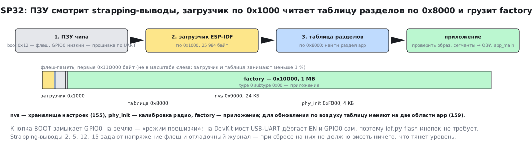
For over-the-air updates the table is changed to two application slots — more on that later in this part. The default values every project is built with:
| Parameter | Default |
|---|---|
| core frequency | 160 MHz |
| FreeRTOS tick | 100 Hz |
stack of the app_main task |
3584 bytes |
| task watchdog (TWDT) | 5 s |
| interrupt watchdog | 300 ms |
| brownout threshold | 2.43 V |
| console | UART0, 115200 baud |
| flash memory size in the header | 2 MB |
Our app_main task runs on core 0 with priority 1, and of the 3584
bytes of stack, 2064 are still free at the end of the program — printing with %p and walking the
partitions cost one and a half kilobytes.
150.6 What carries over from STM32 and what does not
| Concept | STM32 | ESP32 |
|---|---|---|
| core | Cortex-M, one | Xtensa LX6, two (PRO and APP) |
| program | internal flash, XIP | external flash through the cache; hot code in IRAM |
| RAM | one SRAM (plus CCM) | DRAM 328 KB + IRAM + RTC; heap split into banks |
| HAL | CMSIS + HAL/LL, any RTOS | ESP-IDF with FreeRTOS inside, never without the OS |
| build | Keil, CubeIDE, Makefile | CMake through idf.py, menuconfig |
| flashing | ST-Link, SWD | UART through the ROM bootloader, esptool; JTAG separately |
| settings | own flash area, external EEPROM | NVS in the partition table |
| radio | external module | Wi-Fi and Bluetooth on the die |
| sleep | Stop, Standby, backup domain | light/deep sleep, RTC memory, ULP coprocessor |
| debugging without a board | Renode, QEMU for Cortex-M | QEMU from Espressif bundled with ESP-IDF |
What stays the same is everything parts I–IX said about circuit design, interfaces, sensors and power: I²C remains I²C, and Ohm's law remains Ohm's law. What changes are the registers, the API and the pin restrictions.
150.7 Pitfalls
| Symptom | Cause |
|---|---|
| a 4 MB module, but the program sees 2 | the flash memory size in menuconfig is 2 MB by default — set 4 |
Guru Meditation (Cache disabled but cached memory region accessed) while writing to NVS or updating |
a handler with the ESP_INTR_FLAG_IRAM flag calls a function without IRAM_ATTR or reads a constant without DRAM_ATTR, while the cache is off for the write; ordinary handlers simply wait during that time |
malloc of 200 KB returns NULL with 300 KB free |
the heap is made of banks, the largest contiguous piece is 172 KB |
| "GPIO 6…11 do not work" | that is the module's flash memory |
| GPIO 34–39 cannot be switched to output | input only, and without pull-ups or pull-downs |
| the board does not start with a sensor connected | the sensor pulls a strapping pin (0, 2, 5, 12, 15) at reset |
boot:0x… and an endless waiting for download |
GPIO0 is low at reset — the BOOT button or an external pull-down |
| reboots when Wi-Fi is turned on | the supply sags below 2.43 V: a weak regulator or cable |
| chip revision v0.0 in the log | the emulator; on a real chip it comes from eFuse |
150.8 Summary
- A chip without flash memory, the WROOM-32 module with 4 MB and an antenna, a DevKit with USB-UART and buttons.
- Two Xtensa LX6 cores, 160 MHz by default; code and constants in external flash memory through the IROM/DROM cache windows, hot code in IRAM.
soc_caps.h: 35 GPIO numbers, 29 with output; the WROOM-32 has no GPIO20 — 34 pins, 28 with output, 6 taken by flash memory; ADC 8 + 10, DAC 2 × 8 bits, LEDC 8 + 8, MCPWM 12, UART 3, SPI 3, I²C 2, I²S 2, TWAI 1.- Heap 305 KB, the largest piece 172 KB; an empty program takes 40 % of IRAM.
- Boot: ROM by strapping (GPIO0) → ESP-IDF bootloader at
0x1000→ partition table at0x8000→ application at0x10000; 7 image segments. - Defaults: tick 100 Hz, TWDT 5 s,
app_mainstack 3584, brownout 2.43 V.
Full sources
main.c — what the chip is, what lives where in memory and how the flash memory is divided.
/* Раздел 150: что за чип, где что лежит в памяти, как разбита флеш-память.
 * Границы областей берутся из заголовка soc/soc.h ESP-IDF, а не записаны руками. */
#include <inttypes.h>
#include <stdio.h>
#include <stdlib.h>
#include "esp_app_desc.h"
#include "esp_attr.h"
#include "esp_chip_info.h"
#include "esp_flash.h"
#include "esp_heap_caps.h"
#include "esp_partition.h"
#include "esp_system.h"
#include "freertos/FreeRTOS.h"
#include "freertos/task.h"
#include "soc/soc.h"

static const char rodata_text[] = "константа";        /* .rodata — во флеше, читается через кэш */
static int data_var = 42;                             /* .data — во внутреннем ОЗУ данных */
static int bss_var;                                   /* .bss — там же, обнуляется при старте */
RTC_DATA_ATTR static int rtc_var = 7;                 /* медленная память RTC */

static IRAM_ATTR int in_iram(int x) { return x + 1; } /* код во внутреннем ОЗУ команд */
static int in_flash(int x) { return x + 2; }          /* код во флеше через кэш */

static const char *region(uintptr_t a)
{
    if (a >= SOC_DROM_LOW && a < SOC_DROM_HIGH) return "DROM: флеш, данные";
    if (a >= SOC_IROM_LOW && a < SOC_IROM_HIGH) return "IROM: флеш, код";
    if (a >= SOC_IRAM_LOW && a < SOC_IRAM_HIGH) return "IRAM: ОЗУ команд";
    if (a >= SOC_DRAM_LOW && a < SOC_DRAM_HIGH) return "DRAM: ОЗУ данных";
    if (a >= SOC_RTC_DATA_LOW && a < SOC_RTC_DATA_HIGH) return "RTC: медленная память";
    return "?";
}

static void where(const char *what, const void *p)
{
    printf("%-18s 0x%08" PRIxPTR "  %s\n", what, (uintptr_t)p, region((uintptr_t)p));
}

void app_main(void)
{
    esp_chip_info_t ci;
    uint32_t flash = 0;
    int local = 0;

    esp_chip_info(&ci);
    esp_flash_get_size(NULL, &flash);
    printf("chip: model %d, cores %d, revision v%d.%d, wifi %d, bt %d, ble %d\n", ci.model, ci.cores,
           ci.revision / 100, ci.revision % 100, !!(ci.features & CHIP_FEATURE_WIFI_BGN),
           !!(ci.features & CHIP_FEATURE_BT), !!(ci.features & CHIP_FEATURE_BLE));
    printf("flash: %" PRIu32 " KiB, cpu: %d MHz\n", flash / 1024, CONFIG_ESP_DEFAULT_CPU_FREQ_MHZ);
    printf("regions: DROM 0x%08x-0x%08x IROM 0x%08x-0x%08x IRAM 0x%08x-0x%08x DRAM 0x%08x-0x%08x RTC 0x%08x-0x%08x\n",
           SOC_DROM_LOW, SOC_DROM_HIGH, SOC_IROM_LOW, SOC_IROM_HIGH, SOC_IRAM_LOW, SOC_IRAM_HIGH,
           SOC_DRAM_LOW, SOC_DRAM_HIGH, SOC_RTC_DATA_LOW, SOC_RTC_DATA_HIGH);

    where("константа", rodata_text);
    where("data_var", &data_var);
    where("bss_var", &bss_var);
    where("rtc_var", &rtc_var);
    where("in_iram()", (const void *)in_iram);
    where("in_flash()", (const void *)in_flash);
    where("локальная", &local);
    void *h = malloc(1000);
    where("malloc(1000)", h);
    free(h);

    printf("heap: free %u, internal %u, largest block %u\n", (unsigned)esp_get_free_heap_size(),
           (unsigned)heap_caps_get_free_size(MALLOC_CAP_INTERNAL),
           (unsigned)heap_caps_get_largest_free_block(MALLOC_CAP_8BIT));

    esp_partition_iterator_t it = esp_partition_find(ESP_PARTITION_TYPE_ANY, ESP_PARTITION_SUBTYPE_ANY, NULL);
    while (it) {                                      /* на последнем шаге итератор освобождается сам */
        const esp_partition_t *p = esp_partition_get(it);
        printf("part %-9s type %d subtype 0x%02x offset 0x%06" PRIx32 " size 0x%06" PRIx32 "\n",
               p->label, p->type, p->subtype, p->address, p->size);
        it = esp_partition_next(it);
    }

    const esp_app_desc_t *app = esp_app_get_description();
    printf("app: %s, esp-idf %s\n", app->project_name, app->idf_ver);
    printf("task: core %d, priority %u, stack left %u bytes\n", xPortGetCoreID(),
           (unsigned)uxTaskPriorityGet(NULL), (unsigned)uxTaskGetStackHighWaterMark(NULL));
    printf("in_iram(1) = %d, in_flash(1) = %d, data_var = %d, bss_var = %d, rtc_var = %d\n",
           in_iram(1), in_flash(1), data_var, bss_var, rtc_var);
    printf("done\n");
}
Next: section 151 — ESP-IDF and tools: idf.py, menuconfig, components, esptool, the emulator.