 Embedded HandbookApps
161. Power and loads around the ESP32: the regulator, Wi-Fi peaks, switches, relays and spikes
The most common "software" trouble with the ESP32 is not software at all. The module reboots exactly at the moment it turns Wi-Fi on; a relay connected to a pin does not click; after a week of operation a switch burns out. All three have the same nature — the power supply and the loads around the chip.
Here are three models in ngspice 39 (the stm-lab:1 image, files in _verify/esp161/): the dip of the
3.3 V rail at the transmitter's current peak, a switch for a relay coil, and the spike when the coil is switched off. The ESP32 currents
come from the datasheet extract in section 157, the reset threshold from section 150. The model numbers are not
a measurement on a specific board: a real regulator, capacitor and transistor will give different ones,
but the order of magnitude and the conclusions stay the same.
Terms used in the documentation
Term Meaning LDO (low-dropout regulator) a linear regulator with a small voltage drop dropout voltage the minimum input-to-output difference at which the regulator still holds its output output impedance, load transient output resistance, the response to a step in load ESR (equivalent series resistance) the equivalent series resistance of a capacitor brownout detector a supply dip detector: a reset at low voltage peak current the highest current drawn for a short time low-side switch a switch between the load and ground logic-level MOSFET a transistor that turns fully on from a logic level flyback (freewheeling) diode a diode that absorbs the coil's spike TVS diode a suppressor: a limiter for transient overvoltages
161.1 How much the ESP32 draws
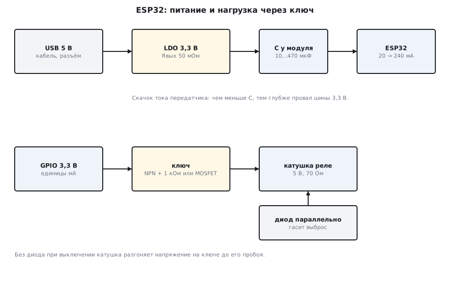
According to the datasheet (section 157) the ESP32 with the radio asleep at 80 MHz draws 20–31 mA, and when transmitting 802.11b — 240 mA. The transition between them takes microseconds: the program turns the transmitter on, and the module's current grows more than tenfold. For the regulator this is a load step, to which it does not respond instantly.
240 mA is a typical value from the table, measured while transmitting with a 50 % duty cycle, not the highest current: the datasheet itself advises a 3.3 V source of 500 mA or more for the ESP32.
161.2 The dip at a Wi-Fi peak: the capacitor at the module
The model: a 3.3 V regulator with a 50 mΩ output resistance; the slow response of its feedback is set by a 10 µH inductance in series with the output; at the module there is a capacitor with an ESR of 50 mΩ; the current steps from 20 to 240 mA. The result for three capacitances:
| Capacitor at the module | Lowest voltage | Dip |
|---|---|---|
| 10 µF | 3.08 V | 215 mV |
| 100 µF | 3.23 V | 66 mV |
| 470 µF | 3.27 V | 30 mV |
While the regulator catches up, the peak current is supplied by the capacitor. With 10 µF the rail dips by 215 mV, to 3.08 V; with 100 µF the dip is 66 mV, with 470 µF — 30 mV. After the peak the voltage settles at 3.288 V: 240 mA across 50 mΩ of output resistance gives 12 mV.
If you plan for the current the datasheet advises sizing the source for — 500 mA — the same model dips more than twice as deep: with 10 µF — by 468 mV, to 2.83 V; with 100 µF — by 143 mV; with 470 µF — by 65 mV.
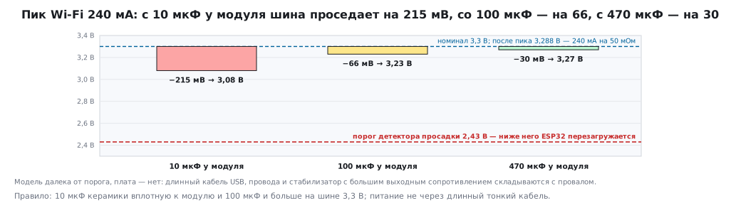
The ESP32 brownout detector threshold is 2.43 V by default (section 150). The model gets nowhere near it, but a real board does: the wires from the source, a thin USB cable and a cheap regulator with a high output resistance add up with the dip. Hence the one rule — next to the module put 10 µF of ceramic and 100 µF or more on the 3.3 V rail, and do not feed it through a long thin cable.
161.3 The USB cable and the regulator dropout
A linear regulator needs headroom between input and output — the dropout; on the old regulators found on development boards it is noticeably larger than on modern low-dropout ones. Everything that sits before the regulator eats this headroom: a thin long USB cable, a connector with poor contact, a reverse-polarity protection diode. At the transmitter's current peak the input voltage dips, the regulator drops out of regulation, and the 3.3 V rail dips next. Hence the classic picture: from one power adapter the board works, from a computer port through a long cable it reboots when connecting to Wi-Fi. A low-dropout regulator, a short thick cable and a capacitor at the regulator input fix this more cheaply than hunting for a bug in the program.
An example with numbers. A computer port, per the USB 2.0 standard, gives 4.75–5.25 V. A 1 m cable with 28 AWG power wires (0.21 Ω per meter, there and back — 0.43 Ω) loses 0.21 V at a peak of 0.5 A, and the Schottky protection diode another 0.36 V or so (the model from section 169). From a port at the lower edge of the standard, 4.75 − 0.21 − 0.36 ≈ 4.2 V reaches the regulator. The AMS1117 — a common regulator on development boards — has a dropout of about a volt and needs at least 4.3 V at its input: at the current peak the output goes down following the input. A regulator with a 0.2 V dropout would be fine even with 3.5 V.
161.4 The pin cannot drive a relay: a transistor switch
A 5 V relay coil with a resistance of 70 Ω needs 5 / 70 = 71.4 mA and five volts. An ESP32 pin gives 3.3 V and up to 40 mA — and only at the maximum drive strength (section 153.2); besides, the coil produces a spike when it is switched off. So a switch is placed between them: the load goes to +5 V, the switch — between the load and ground. A model of two variants, with the switch turned on by a 3.3 V pin:
npn: Ib_A=0.00250827 Ic_A=0.0698165 Vce_V=0.112847
mosfet: Id_A=0.0713696 Vds_V=0.00412546
The NPN with a 1 kΩ base resistor takes 2.5 mA from the pin and passes 69.8 mA through the coil; across the transistor itself 0.11 V remains — it is in saturation. The MOSFET with a 1.5 V threshold passes 71.4 mA, only 4 mV drops across it, and the steady-state gate current is zero.
161.5 NPN or MOSFET
- NPN is cheap and forgives a lot. The base current is set by a resistor with a margin so that the transistor goes into saturation: in the model a 1 kΩ resistor gives 2.5 mA into the base, and 0.11 V remains across the switch. At currents of amperes this drop already heats the transistor.
- MOSFET barely loads the pin and barely heats up, but it must be a "logic-level" one — fully turning on from 3.3 V; in the model the threshold is 1.5 V, and only 4 mV remains across the switch. A transistor with a high threshold from power circuits will turn on only partially from an ESP32 pin and will heat up. A small gate resistor damps ringing, and a resistor from the gate to ground holds the switch off until the pin is configured: during boot the ordinary ESP32 pins have no pull-ups and float.
The pin for the switch itself is chosen among those with no special role at reset. The five strapping pins — 0, 2, 5, 12 and 15 (section 153.3) — latch their level at the moment of reset, and the switch circuitry changes it: a 10 kΩ resistor from the gate to ground overpowers the internal 45 kΩ pull-up, GPIO0 is left at 0.6 V — below the 0.825 V low threshold — and the chip goes into flashing mode; an NPN base through 1 kΩ pulls GPIO0 down the same way, to 0.77 V. On GPIO15 the same resistor turns off the boot log, and a switch with a pull-up on GPIO12 will switch the flash memory supply to 1.8 V. Pins 1 and 3 are TX and RX of UART0: TX is pulled up at reset and immediately sends the log, so a switch on it will turn on at startup and twitch. Pins 16–19, 21–23, 25–27, 32 and 33 are suitable: at reset they have neither pull-ups nor a special role (on modules with PSRAM, 16 and 17 are taken by it).
161.6 The coil spike and the diode
The current through a coil cannot vanish instantly. When the switch turns off, the coil drives up the voltage on the drain until the current finds a path. The model of a 70 Ω / 100 mH coil, the switch turning off:
diode=0 Vpeak_V=60.211
diode=1 Vpeak_V=5.84563
Without a diode the voltage on the switch reaches 60 V — up to the transistor's breakdown in the model. A real switch breaks down like this on every turn-off and one day fails, and the spike through ground and supply resets the ESP32. With a diode in parallel with the coil (cathode to +5 V) the spike is limited to 5.8 V: the supply plus the diode drop, and the coil current decays calmly through the diode.
A plain diode slows down the release: the coil current decays slowly, the contacts open later and arc longer. Where this matters, a Zener diode is placed in series with the diode. The spike is then limited to the supply plus the Zener voltage — it must be lower than the switch's limit. In the same model with a 24 V Zener the spike is 30 V, and the current drops to 10 % in 0.23 ms instead of 2.2 ms with a diode alone.
For relays and motors the diode is mandatory. If the load is far away, on long wires, a suppressor (TVS) is also added at the board input: it limits pulses coming from outside.
161.7 Pitfalls
| Symptom | Cause |
|---|---|
| the ESP32 reboots when Wi-Fi turns on | a dip on the 3.3 V rail: too little capacitance at the module, a thin cable, a weak regulator |
| reboots only from a computer's USB | a long cable and a connector eat the regulator's headroom |
| the relay does not click from a pin | the pin gives 3.3 V and no more than 40 mA, while the coil needs 5 V and 71 mA — you need a switch |
| the MOSFET heats up, the relay clicks unreliably | the transistor is not logic-level: at 3.3 V it is not fully on |
| the relay twitches when the board powers up | the gate has no resistor to ground, the pin is not configured during boot |
| after adding a switch the board does not boot or waits for flashing | a switch on a strapping pin (0, 2, 5, 12, 15) changes the level latched at reset |
| the switch burns out after a week | no diode on the coil: a spike up to breakdown on every turn-off |
| the ESP32 resets when a relay or motor turns off | the coil spike travels through ground and supply |
| a transistor in saturation does not hold the current | too little base current: the base resistor is too large |
161.8 Summary
- ESP32: 20–31 mA with the radio asleep, 240 mA when transmitting; the step happens within microseconds; the source per the datasheet — from 500 mA.
- The dip model: 10 µF — 215 mV, 100 µF — 66 mV, 470 µF — 30 mV; after the peak 3.288 V.
- The ESP32 reset threshold is 2.43 V; the cable, the connector and the regulator eat the headroom.
- A 5 V / 70 Ω coil: an NPN with a 1 kΩ base resistor — 69.8 mA with 0.11 V across the switch, a MOSFET — 71.4 mA with 4 mV.
- The coil spike without a diode — up to 60 V (switch breakdown), with a diode — 5.8 V.
- Next to the module 10 µF and 100 µF or more; loads — through a switch; on the coil — a diode.
Next: section 162 "Single-supply path to the ADC: y = m·x + b".