 Embedded HandbookApps
22н. E-paper display with the SSD1680 controller over SPI: BUSY, full and partial update, LUT, black and red buffers, sleep and battery power
In 22з the colour TFT drew through windows straight into its own memory, in 22м the monochrome OLED received a finished frame from RAM — and both shone only while powered. The general view of displays is in 22а. Here is a screen that does not show a picture but keeps it: electronic paper. Cut the power — the text stays. In return a frame takes seconds to change, the screen flashes while doing so, and frequent quick updates leave traces. The 2.13″ 250×122 and 2.9″ 296×128 modules on the SSD1680 controller, four SPI wires and a BUSY line; initialisation, the two memories — black and red — full and partial update, bytes and rotation, deep sleep and a battery estimate for a weather station that updates its screen every 10 minutes. And the pitfalls: not waiting for BUSY, waking without a reset, a partial update without a base frame, inverted bits, frost.
Sources: RM0008 (DocID13902 Rev 17): wait for TXE, then BSY, p. 719;
the BR divider — from /2, p. 743. DocID13587 Rev 17 (STM32F103x8/xB):
20 Kbytes of RAM, p. 1; PA1–PA7 not 5 V tolerant, PA5 is SPI1_SCK, PA7 is
SPI1_MOSI, p. 29; run current at 8 MHz up to 8.6 mA, p. 42; Stop with the
low-power regulator 14 µA, Standby with LSI and no watchdog 3.2 µA at 3.3 V,
p. 45. The project has no SSD1680 datasheet. The command codes and their
byte counts, the bits of command 0x22 and the codes 0xF7 and 0xFF, data
entry mode 0x11, deep sleep 0x10 0x01, "SW reset leaves the RAM intact",
"BUSY = 1 means busy", "after a partial update the memories are swapped",
"the most significant bit is the first pixel", 1 is white in the black
memory, the SSD1680 handles up to 296×176 pixels, the 2.13″ module is
250×122 with its internal sensor 0x80, border 0x05 and 0x3C and SPI at
4 MHz — were checked against the SSD16xx driver and boards of Zephyr 4.4.2
on disk. How the paper works physically, the update duration, the module
currents, behaviour in sleep and on reset, garbage in memory after power-up
and the accumulation of ghosts follow the manufacturer's documentation and
were not checked: in the model they are assumptions, and the numbers about
them describe the model, not the glass. All other numbers below come from
running the driver _verify/epd22n/epd22n.c, built with
arm-none-eabi-gcc 12.2.1 for the Cortex-M3 and run in QEMU 7.2
(mps2-an385), against its own SSD1680 model in Python 3.11; in the bench
SPI, RST and BUSY are replaced by text lines over semihosting, and the
model compares the glass with a reference pixel by pixel. The F103
firmware is built with armclang 6.24.
What it is called in the documentation
Original Meaning electrophoretic display (EPD), e-paper electrophoretic display, electronic paper microcapsule, charged pigment particles a capsule with charged ink particles bistable the picture holds without power Driver Output Control (0x01) how many rows the glass has and how to scan them Data Entry Mode (0x11) where the memory pointer goes after a byte BW RAM (0x24), RED RAM (0x26) the black memory and the red memory Display Update Control 2 (0x22), Master Activation (0x20) what to do on update, and "go" Display Mode 1 / Display Mode 2 full and partial update LUT (waveform look-up table) the voltage waveform table: what to apply to a pixel and for how long TSSV (0x18), internal sensor 0x80 which temperature sensor to use Border Waveform Control (0x3C) what to do with the border around the field image retention (residual image) a residual image — a "ghost" DSM (0x10 0x01) deep sleep: exit only through RST
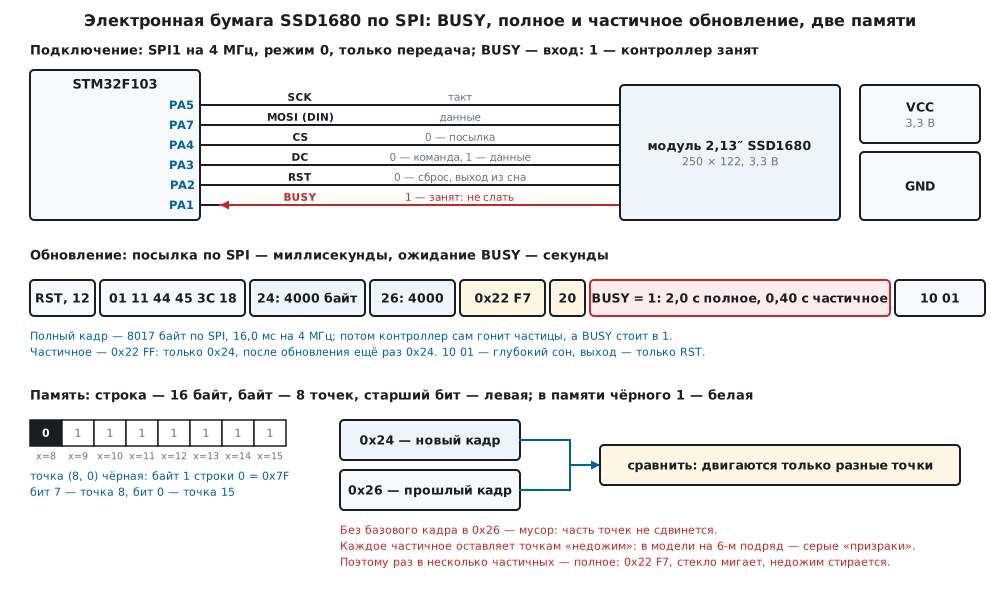
22н.1 The paper, the modules and the pins
How the paper works (according to manufacturers' descriptions, not checked). The field is a layer of tiny capsules with clear liquid in which charged particles float: white of one sign, black of the other (in three-colour panels also red). A voltage between the top and bottom electrodes pulls one kind of particle towards the viewer and hides the other. Remove the voltage and the particles stay where they are: the picture holds without power, and current flows only while it changes. Hence three properties the program has to deal with:
- a frame changes slowly: the particles move through liquid, and the controller drives each pixel by a voltage table (LUT) — a series of pulses of different sign, not a single switch;
- a full update flashes: for a pixel to reach the exact colour regardless of the previous one, it is driven through black and white — the whole screen blinks;
- in the cold the liquid is thicker, the particles are slower, and the same table takes longer; that is why the controller picks the table by temperature.
The model does not compute any of this — only the consequences: an update holds BUSY for a set time, a partial update accumulates "underdrive" (22н.5), cold stretches the time (22н.7).
Modules. In Zephyr 4.4.2 the SSD1680 is described as a controller of up to 296×176 pixels; next to it in the same driver are its relatives SSD1608, SSD1673, SSD1675A and SSD1681 with their own limits. The older generation (SSD1608, SSD1673, SSD1675A) has different bits in command 0x22, so "compatible" does not mean "the same code". This section uses two SSD1680 modules:
| Module | Pixels | Memory X × Y | Bytes per colour |
|---|---|---|---|
| 2.13″ | 250 × 122 | 16 bytes × 250 rows | 4000 |
| 2.9″ | 296 × 128 | 16 bytes × 296 rows | 4736 |
The controller memory is organised in rows: X is 8 pixels per byte, Y is the row number. The short side of the glass is X: 122 and 128 pixels give 16 bytes each. The long side is rows: 250 and 296. That is how Zephyr describes the 2.13″ module: 250 wide, 122 high, sensor 0x80, border 0x05 and 0x3C, SPI at 4 MHz.
Pins. The bus is transmit-only SPI (Zephyr connects such modules as "4-wire SPI": clock, data, CS and the DC line), plus reset and BUSY:
| Module | STM32F103 | What |
|---|---|---|
| CLK (SCK) | PA5 | SPI1 clock |
| DIN (MOSI) | PA7 | SPI1 data |
| CS | PA4 | 0 — a transfer is in progress |
| DC | PA3 | 0 — command byte, 1 — its data |
| RST | PA2 | 0 — reset; only it wakes from deep sleep |
| BUSY | PA1, input | 1 — the controller is busy, send no commands |
| VCC, GND | 3.3 V and ground |
PA1–PA7 are not 5 V tolerant (DocID13587, p. 29): power the module from
3.3 V. In the firmware the core stays on HSI 8 MHz, as after reset: a
battery device does not need 72 MHz. SPI1 uses the /2 divider (RM0008,
p. 743), 4 MHz, as for the module in Zephyr; mode 0. A transfer is a command
with DC = 0, then its data with DC = 1, all under one CS = 0. Change DC only
when the byte has gone completely: TXE, then BSY (p. 719):
/* CS = 0 на всю посылку; DC = 0 — байт команды, DC = 1 — её данные. DC менять только когда SPI пуст */
void epd_port_cmd(uint8_t cmd, const uint8_t *data, uint32_t n)
{
    CLR(PIN_CS);
    CLR(PIN_DC);
    spi_byte(cmd);
    spi_idle();
    SET(PIN_DC);
    while (n--)
        spi_byte(*data++);
    spi_idle();
    SET(PIN_CS);
}
22н.2 Initialisation: reset, SW reset, BUSY and the memory window
The order is as in the Zephyr driver: a hardware reset, wait for BUSY, SW reset 0x12, wait for BUSY again, then the setup. SW reset returns the registers to their defaults and leaves the memory intact (Zephyr says so) — so the program does not have to resend the frame after every reset.
/* Аппаратный сброс, SW reset 0x12 и настройка: строки, режим ввода, окно памяти, рамка, датчик, указатель.
 * Память контроллера сброс не трогает: что было в памяти красного, то и осталось. */
static int controller_init(epd_t *e)
{
    const uint16_t last = (uint16_t)(e->p->gates - 1u);
    const uint8_t gdo[3] = {(uint8_t)last, (uint8_t)(last >> 8), 0x00};
    const uint8_t wx[2] = {0x00, (uint8_t)(EPD_STRIDE - 1u)};
    const uint8_t wy[4] = {0x00, 0x00, (uint8_t)last, (uint8_t)(last >> 8)};
    const uint8_t y0[2] = {0x00, 0x00};
    int rc;
    epd_port_rst(0);
    epd_port_delay_ms(10);
    epd_port_rst(1);
    epd_port_delay_ms(10);
    if ((rc = epd_wait(e)) != EPD_OK)
        return rc;
    cmd(e, EPD_SW_RESET, 0, 0);
    if ((rc = epd_wait(e)) != EPD_OK)
        return rc;
    cmd(e, EPD_DRIVER_OUT, gdo, 3);
    cmd1(e, EPD_ENTRY_MODE, EPD_ENTRY_XINC_YINC);
    cmd(e, EPD_RAM_X, wx, 2);
    cmd(e, EPD_RAM_Y, wy, 4);
    cmd1(e, EPD_BORDER, EPD_BORDER_FULL);
    cmd1(e, EPD_TEMP_SENSOR, EPD_TSENSOR_INTERNAL);
    cmd1(e, EPD_RAM_XCNT, 0x00);
    cmd(e, EPD_RAM_YCNT, y0, 2);
    e->asleep = 0;
    return epd_wait(e);
}
What went to the 2.13″ module (model log):
| Command | Data | What |
|---|---|---|
| RST | — | pin to 0 for 10 ms, then wait for BUSY |
12 |
— | SW reset; BUSY = 1 while it runs |
01 |
F9 00 00 |
250 rows: 249 = 0x00F9 low byte first, and 0x00 |
11 |
03 |
X increments, Y increments, X first — as the buffer is laid out |
44 |
00 0F |
X window: bytes 0…15 |
45 |
00 00 F9 00 |
Y window: rows 0…249 |
3C |
05 |
border — as for this module in Zephyr for a full update |
18 |
80 |
internal temperature sensor |
4E, 4F |
00, 00 00 |
pointer to the start of the window |
After the reset — 9 commands, 24 bytes, 48 µs at 4 MHz; the
2.9″ module differs in two: 01 27 01 00 and 45 00 00 27 01 — 296 rows.
Waiting for BUSY is a function of a few lines, but with a timeout: if the
module is disconnected or broken, BUSY may stay at 1 forever.
/* BUSY = 1 — контроллер занят: команды сейчас не слать. Ждём с шагом EPD_POLL_MS, но не дольше timeout_ms */
int epd_wait(epd_t *e)
{
    uint32_t t = 0;
    while (epd_port_busy()) {
        if (t >= e->timeout_ms)
            return EPD_E_TIMEOUT;
        epd_port_delay_ms(EPD_POLL_MS);
        t += EPD_POLL_MS;
    }
    e->last_busy_ms = t;
    return EPD_OK;
}
In the firmware epd_port_delay_ms sleeps in WFI until the SysTick tick:
while BUSY is high, the core sleeps. The polling step is 10 ms; for a full
update the model counted 202 BUSY polls.
22н.3 Two memories, bytes and rotation
The controller has two memories of the same size: 24 — black, 26 —
red. In the black memory bit 1 is a white pixel, 0 is black (Zephyr fills
it with 0xFF to make the screen white). In the red memory of a three-colour
module 1 is a red pixel. A black-and-white module has no red, and the
second memory serves as the "previous frame" for a partial update (22н.5).
A byte is 8 neighbouring pixels of a row, the most significant bit is the
leftmost (in Zephyr — SCREEN_INFO_MONO_MSB_FIRST). This is not like the
SSD1306 in 22м, where a byte is a column of 8 pixels and the least
significant bit is on top:
/* Байт — 8 точек строки, старший бит — левая: точка sx строки gy — байт gy × 16 + sx / 8, бит 7 − sx % 8 */
void epd_pixel(epd_t *e, int x, int y, uint8_t color)
{
    uint32_t sx, gy, i;
    uint8_t m;
    if (!map_xy(e, x, y, &sx, &gy))
        return;
    i = gy * EPD_STRIDE + (sx >> 3);
    m = (uint8_t)(0x80u >> (sx & 7u));
    if (color == EPD_BLACK)
        e->bw[i] &= (uint8_t)~m;        /* 0 — чёрная */
    else
        e->bw[i] |= m;                  /* 1 — белая; под красной точкой тоже белая */
    if (color == EPD_RED)
        e->red[i] |= m;
    else
        e->red[i] &= (uint8_t)~m;
}
The driver set one pixel on a white screen, and the model found the single changed byte and the single black pixel on the glass:
| Pixel | Rotation | Byte | Value | Memory row, column |
|---|---|---|---|---|
| (0, 0) | 0 | 0 | 0x7F | 0, 0 |
| (7, 0) | 0 | 0 | 0xFE | 0, 7 |
| (8, 0) | 0 | 1 | 0x7F | 0, 8 |
| (121, 0) | 0 | 15 | 0xBF | 0, 121 |
| (0, 249) | 0 | 3984 | 0x7F | 249, 0 |
| (0, 0) | 1 | 15 | 0xBF | 0, 121 |
| (249, 121) | 1 | 3984 | 0x7F | 249, 0 |
A row is 16 bytes, but the 2.13″ module has 122 = 15 × 8 + 2 pixels: the
last byte of a row uses its two top bits, and the glass does not show the
six low ones. The buffer is 16 × 250 = 4000 bytes per colour, for the 2.9″ —
16 × 296 = 4736. The epd_t type holds both colours for the larger module:
armclang showed 9516 bytes of static memory in the firmware — 46 % of
the 20 Kbytes of the F103C8 (DocID13587, p. 1). A black-and-white module
would need one buffer.
Rotation. The memory is portrait: 122 pixels in X and 250 rows. A
weather station needs landscape 250×122. The driver does not touch the data
entry mode; it recalculates the pixel in map_xy:
/* Точка (x, y) экрана → столбец памяти sx и строка gy с учётом поворота */
static int map_xy(const epd_t *e, int x, int y, uint32_t *sx, uint32_t *gy)
{
    const int s = (int)e->p->sources, g = (int)e->p->gates;
    int a, b;
    if (x < 0 || y < 0 || x >= epd_width(e) || y >= epd_height(e))
        return 0;
    switch (e->rot) {
    case 1:  a = s - 1 - y; b = x;          break;
    case 2:  a = s - 1 - x; b = g - 1 - y;  break;
    case 3:  a = y;         b = g - 1 - x;  break;
    default: a = x;         b = y;          break;
    }
    *sx = (uint32_t)a;
    *gy = (uint32_t)b;
    return 1;
}
With rotation 1, screen pixel (0, 0) is column 121 of row 0, byte 15, 0xBF; pixel (249, 121) is column 0 of row 249. The buffer stays in memory axes and goes to the module as is.
Entry mode and pointer — together. The controller can turn the picture 180°
in Y by itself: 11 01 — Y decrements. But then the 4F pointer must sit
on the last row. In the model 11 01 with the pointer on row 0 gave an
upside-down picture shifted by a row: 2010 pixels different from the
flipped reference; with the pointer on row 249 — 0 differences.
Zephyr does the same: before clearing it sets a mode with decrementing Y and
the pointer on the last row.
22н.4 Full update: 0x24, 0x26, 0x22 and 0x20
Writing a frame is the pointer to the start and one transfer: the command and 16 × rows data bytes.
/* Весь цвет в память контроллера: указатель в начало окна, потом 0x24 или 0x26 и 16 × строк байт */
static void write_plane(epd_t *e, uint8_t ram, const uint8_t *buf)
{
    static const uint8_t y0[2] = {0x00, 0x00};
    cmd1(e, EPD_RAM_XCNT, 0x00);
    cmd(e, EPD_RAM_YCNT, y0, 2);
    cmd(e, ram, buf, epd_bytes(e));
}
The display itself is two commands: 22 says what to do, 20 starts it.
The bits of 22 come from Zephyr's ssd16xx_regs.h:
| Bit | What |
|---|---|
| 0x80, 0x40 | enable the oscillator and the analog part |
| 0x20 | read the temperature from the sensor |
| 0x10 | load the voltage waveform table (LUT) from OTP |
| 0x08 | the second mode — partial update |
| 0x04 | display |
| 0x02, 0x01 | disable the analog part and the oscillator |
Full is everything except 0x08: 0xF7; partial is everything: 0xFF. That is how Zephyr builds them for the SSD1680 with the internal sensor. Code 0xFC is the same partial without the last two bits: the oscillator and the analog part stay on after the update. The section's driver does not send it; what it gives in time and current follows the manufacturer's documentation and was not checked.
/* 0x22 и 0x20, потом BUSY: через 1 мс он обязан стоять в 1 — иначе контроллер спит или не подключён */
static int activate(epd_t *e, uint8_t ctrl2)
{
    cmd1(e, EPD_UPDATE_CTRL2, ctrl2);
    cmd(e, EPD_MASTER_ACT, 0, 0);
    epd_port_delay_ms(1);
    if (!epd_port_busy())
        return EPD_E_NOBUSY;
    return epd_wait(e);
}
After 20 BUSY must rise. If it is still 0 after 1 ms, the commands did not
arrive: the controller is asleep or the module is disconnected (22н.7), and
the driver returns EPD_E_NOBUSY instead of "done".
int epd_show(epd_t *e, int mode)
{
    int rc;
    if (e->asleep && (rc = controller_init(e)) != EPD_OK)     /* из сна выводит только аппаратный сброс */
        return rc;
    if (mode == EPD_AUTO)
        mode = e->kind == EPD_KIND_BWR || !e->base_ok || (e->full_every && e->partials >= e->full_every)
                   ? EPD_FULL : EPD_PARTIAL;
    if (mode == EPD_PARTIAL && (!e->base_ok || e->kind == EPD_KIND_BWR))
        return EPD_E_NOBASE;
    if (mode == EPD_FULL) {
        /* у чёрно-белого память красного — «прошлый кадр»: кладём туда тот же кадр, он станет базой */
        write_plane(e, EPD_WRITE_BW, e->bw);
        write_plane(e, EPD_WRITE_RED, e->kind == EPD_KIND_BWR ? e->red : e->bw);
        cmd1(e, EPD_BORDER, EPD_BORDER_FULL);
        if ((rc = activate(e, EPD_UPD_FULL)) != EPD_OK)
            return rc;
        e->base_ok = e->kind == EPD_KIND_BW;
        e->partials = 0;
        e->fulls++;
        return EPD_OK;
    }
    /* частичное: двигаются только точки, где новый кадр (0x24) отличается от прошлого (0x26) */
    write_plane(e, EPD_WRITE_BW, e->bw);
    cmd1(e, EPD_BORDER, EPD_BORDER_PART);
    if ((rc = activate(e, EPD_UPD_PART)) != EPD_OK)
        return rc;
    write_plane(e, EPD_WRITE_BW, e->bw);   /* после частичного память поменялась местами (так в Zephyr): ещё раз */
    e->partials++;
    e->parts++;
    return EPD_OK;
}
A full update puts the frame into both memories: into 24 as the new one,
into 26 as the future base for a partial update. The weather station
frame in the model:
| What | Value |
|---|---|
| over SPI | 8017 bytes, 16.0 ms at 4 MHz |
| BUSY = 1 (model, 25 °C) | 2.0 s, the driver measured 2000 ms in steps of 10 |
| glass differences from the reference | 0 of 30500 pixels, 5075 black |
The transfer is 0.8 % of the update time: there is little point in speeding up SPI or adding DMA here, all the time goes to the particles.
LUT. The controller takes the voltage waveform from its OTP memory —
bit 0x10 in 22 — and chooses the one for the temperature by the sensor —
bit 0x20 and command 18 80. You can load your own table with command 32
(in Zephyr — in the full and partial profiles), but its contents for a
particular glass can only come from its manufacturer: a table from another
module can spoil the picture. The section's driver sends no LUT of its own.
22н.5 Partial update and ghosts
A partial update does not drive the whole screen through black and white.
The controller compares the two memories: 24 holds the new frame, 26
the previous one, and moves only the pixels where they differ. There is no
flashing, and in the model the update takes 0.40 s instead of 2.0
(per the manufacturer's documentation, not checked). After the update the
memories are swapped — Zephyr says so — and 24 ends up with the previous
frame. So after a partial update the driver sends the new frame to 24
once more: now both memories hold what is on the glass, and the next
partial update starts from the right base. Model log: 24 3C:3C 22:FF 20 24.
From frame "00:00" to "00:10" 1332 pixels had to change in the
model — exactly that many moved; glass differences from the reference
0, both memories matched after the update. Over SPI — the same
8017 bytes: 24 twice.
Ghosts. A partial update drives a pixel for less time than a full one, and the pixel does not quite reach its colour — some "underdrive" remains. It accumulates from update to update, and where the digits changed most often grey traces appear. In the model this is an assumption: each partial update adds 0.02 to a repainted pixel and 0.002 to the others, and a pixel with underdrive above 0.10 looks grey. A full update erases everything. The weather station ran partial updates in a row:
| Partial updates in a row | Grey pixels | Largest underdrive |
|---|---|---|
| 5 | 0 | 0.100 |
| 6 | 79 | — |
| 10 | 684 | 0.200 |
| 20 | 2636 | 0.400 |
| 30 | 2778 | 0.600 |
The first grey pixels appear on partial update 6, in the
temperature and humidity digits. Hence the driver's rule: after 5 partial
updates — a full one (full_every = 5, EPD_AUTO). A day of the weather
station — 144 updates every 10 minutes — gave 24 full and 120 partial
updates, 0 grey pixels, 0 differences from the reference over the
whole day. The number 5 follows from the model's assumptions; on real glass
it is chosen by eye.
Border. The field is surrounded by a border with its own waveform —
command 3C. For a full update of the 2.13″ module Zephyr uses 0x05, for a
partial one 0x3C; the driver sets it before every update.
Three-colour module. On a module with red, 26 is the red colour, and
there is no "previous frame". The driver does no partial updates for it:
epd_show with EPD_PARTIAL returned EPD_E_NOBASE (−3). A full
update in the model — 304 red pixels of the word "ALERT",
0 differences.
22н.6 Sleep and the battery: a weather station every 10 minutes
Between updates the module needs nothing: the picture holds by itself. So
after an update — deep sleep 10 01. The only way out is a hardware reset;
the controller does not listen to SPI meanwhile.
int epd_sleep(epd_t *e)
{
    int rc = epd_wait(e);
    if (rc != EPD_OK)
        return rc;
    cmd1(e, EPD_DEEP_SLEEP, EPD_SLEEP_MODE1);
    e->asleep = 1;
    return EPD_OK;
}
epd_show remembers that the controller is asleep and starts with
controller_init: RST, 12, setup. In the model the memory survives sleep
(per the manufacturer's documentation, not checked), and the next partial
update goes from the same base.
Energy of one update. The module currents in the model are assumptions: 4.0 mA on average during an update, 30 µA without sleep, 1 µA in sleep. At 3.3 V:
| What | Time (model) | Energy | Charge |
|---|---|---|---|
| full | 2.0 s | 26.40 mJ | 2.222 µAh |
| partial | 0.40 s | 5.28 mJ | 0.444 µAh |
| SPI transfer, core running (8.6 mA) | 16.0 ms | 456.4 µJ |
A day. The weather station wakes every 10 minutes, draws a frame (program work is an assumption: 20 ms at 8 MHz, 8.6 mA per DocID13587, p. 42), sends it, waits for BUSY asleep and sleeps until next time in Stop — 14 µA (p. 45). The battery is the same as in 79.3: 220 mAh. The numbers of full and partial updates come from the daily run (24 and 120):
| How | Module, mAh per day | MCU, mAh per day | Average current | Lasts, days (years) |
|---|---|---|---|---|
| partial, full after 5, module asleep, MCU in Stop | 0.131 | 0.348 | 19.96 µA | 459 (1.26) |
| full updates only | 0.344 | 0.348 | 28.85 µA | 318 (0.87) |
| module not asleep | 0.826 | 0.348 | 48.93 µA | 187 (0.51) |
| MCU waits for BUSY running | 0.131 | 0.577 | 29.50 µA | 311 (0.85) |
| MCU sleeps in Standby | 0.131 | 0.089 | 9.16 µA | 1001 (2.74) |
You can see who eats the battery. In the right mode the module spends less
than half of what the MCU does: only updates are expensive, and there are
144 of them a day. Module sleep matters: without 10 01 its 30 µA of idle
current (a model assumption) add up over a day to more than all the
updates together. Waiting for BUSY running rather than asleep gives an
average current of 29.50 µA instead of 19.96. And the MCU itself
gives the most: Stop on the F103 is 14 µA, and sleeping in Standby (3.2 µA
with LSI for the alarm, p. 45) makes the battery last more than twice as
long. Standby means a reset on exit (section 10.4): epd_t and the partial
counter must be kept in the backup registers, and the frame redrawn — it is
redrawn every time anyway.
22н.7 Pitfalls
Commands did not wait for BUSY — some were lost. While BUSY = 1 the
controller does not listen (so in the model; per the manufacturer's
documentation, not checked). A partial update followed immediately, without
waiting for BUSY, by a second 24 and sleep: in the model 4 commands
were lost, the glass showed the new frame, but the black memory kept the
previous one, and the module did not go to sleep — those 30 µA instead of 1.
Wait for BUSY before every command after 12 and 20.
After sleep the screen does not change, and there are no errors. A
controller in deep sleep does not hear SPI, and its BUSY is 0 — a naive
driver concludes the update finished instantly. In the model 9 commands
went nowhere, the glass shows the previous frame (0 differences from
it). The section's driver catches this itself: BUSY did not rise after
20 — EPD_E_NOBUSY (−2). Only RST wakes it: after a reset and
controller_init the next partial update went through, 0 differences.
A partial update without a base frame is a mess. After power-up the
controller memory holds garbage (a model assumption), while the glass keeps
the previous picture. A partial update compares the new frame with garbage
and does not move pixels where the garbage happens to match the new frame.
In the model, of the 1332 pixels that had to change, 673 ended up
wrong. The first display after power-up must be full; epd_init clears
base_ok, and EPD_AUTO does a full one itself: 0 differences.
A negative, mirrored groups of eight, all red. In the black memory 1 is white. A buffer with "1 is black" gives a negative: in the model all 30500 pixels differ. Least significant bit on the left — every group of eight pixels is mirrored: 5874 differences. On a three-colour module a red memory filled with 0xFF instead of 0x00 makes the whole screen red: 30500 pixels of 30500.
Picture upside down and shifted by a row. An entry mode with decrementing Y but the pointer left on row 0 — 22н.3: 2010 differences from the flipped reference. Change the mode and the pointer together.
A timeout in the frost. The cold table takes longer. In the model (an assumption) the update time grows like this, and a driver with a 3 s timeout breaks already at 5 °C:
| Temperature | Full | Partial | 3 s timeout | 10 s timeout |
|---|---|---|---|---|
| 25 °C | 2.0 s | 0.40 s | ok | ok |
| 15 °C | 2.6 s | 0.52 s | ok | ok |
| 5 °C | 3.6 s | 0.72 s | EPD_E_TIMEOUT |
ok |
| −5 °C | 5.2 s | 1.04 s | EPD_E_TIMEOUT |
ok |
| −15 °C | 8.0 s | 1.60 s | EPD_E_TIMEOUT |
ok |
Choose the timeout with a margin for the coldest case: the driver uses 10 s. The update time grows in the cold — and so do the charge and energy.
A 5 V module. PA1–PA7 on the F103 are not 5 V tolerant (DocID13587, p. 29): do not connect a module with 5 V logic to them directly.
22н.8 Summary
- Electronic paper holds the picture without power; current flows only during an update. SSD1680: transmit-only SPI, DC, CS, RST and BUSY (1 — busy).
- Initialisation: RST,
12, wait for BUSY;01 F9 00 00,11 03,44 00 0F,45 00 00 F9 00,3C 05,18 80,4E/4F— 9 commands and 24 bytes on the 2.13″; on the 2.9″ —01 27 01 00and 296 rows. - Memory in rows: a byte is 8 pixels, the most significant bit is the leftmost; in the black memory 1 is white. Pixel (8, 0) is byte 1, 0x7F. The buffer is 4000 bytes per colour on the 2.13″ and 4736 on the 2.9″.
- Full:
24and26,22 F7,20, BUSY — 2.0 s in the model; over SPI 8017 bytes in 16.0 ms. Partial:22 FF, 0.40 s, only changed pixels move (1332 of 30500); after it24once more. - Ghosts: in the model on partial update 6 in a row; a full update after 5 partial ones — a day without a single grey pixel (24 full, 120 partial).
- Sleep
10 01, exit only through RST; without RST commands are lost, and a driver that does not check BUSY will think all went well. - A weather station every 10 minutes on a 220 mAh battery lasts 459 days; without module sleep — 187, with the MCU in Standby — 1001.
Full sources
epd22n.h — SSD1680 commands and bits, the epd_t type with the black and red buffers, the port and the driver prototypes.
/* epd22n.h — раздел 22н: дисплей на электронной бумаге с контроллером SSD1680 по SPI без регистров микроконтроллера.
 * Драйвер говорит с модулем через epd_port_*: в прошивке fw22n.c их делают SPI1 и выводы STM32F103, в стенде
 * host22n.c — строки через semihosting к модели model22n.py (QEMU). Коды команд, биты 0x22, режим 0x11, 0x10 0x01,
 * датчик 0x18 0x80, рамка 0x05 / 0x3C, «старший бит — левая точка», размеры модулей и 4 МГц сверены с драйвером
 * SSD16xx и платами Zephyr 4.4.2 на диске; даташита SSD1680 в проекте нет. */
#ifndef EPD22N_H
#define EPD22N_H
#include <stdint.h>

/* ── команды SSD1680 ───────────────────────────────────────────────────── */
#define EPD_DRIVER_OUT    0x01u         /* + 3 байта: (строк − 1) младшим байтом вперёд и 0x00 */
#define EPD_DEEP_SLEEP    0x10u         /* + 1 байт: 0x01 — глубокий сон, выход только аппаратным сбросом */
#define EPD_ENTRY_MODE    0x11u         /* + 1 байт: куда идёт указатель после байта */
#define EPD_SW_RESET      0x12u         /* программный сброс: регистры по умолчанию, память не трогает */
#define EPD_TEMP_SENSOR   0x18u         /* + 1 байт: 0x80 — свой датчик температуры */
#define EPD_MASTER_ACT    0x20u         /* запустить последовательность, заданную 0x22 */
#define EPD_UPDATE_CTRL2  0x22u         /* + 1 байт: что делать при 0x20 (биты ниже) */
#define EPD_WRITE_BW      0x24u         /* + данные: память чёрного (новый кадр) */
#define EPD_WRITE_RED     0x26u         /* + данные: память красного (у чёрно-белого — прошлый кадр) */
#define EPD_WRITE_LUT     0x32u         /* + данные: своя таблица формы напряжений вместо OTP */
#define EPD_BORDER        0x3Cu         /* + 1 байт: что делать с рамкой вокруг поля */
#define EPD_RAM_X         0x44u         /* + 2 байта: окно по X в байтах, от и до */
#define EPD_RAM_Y         0x45u         /* + 4 байта: окно по Y в строках, от и до, младшим вперёд */
#define EPD_RAM_XCNT      0x4Eu         /* + 1 байт: указатель X */
#define EPD_RAM_YCNT      0x4Fu         /* + 2 байта: указатель Y */

/* ── биты 0x22 (как в ssd16xx_regs.h Zephyr) ───────────────────────────── */
#define EPD_U_CLK_ON      0x80u
#define EPD_U_ANALOG_ON   0x40u
#define EPD_U_LOAD_TEMP   0x20u
#define EPD_U_LOAD_LUT    0x10u
#define EPD_U_MODE2       0x08u         /* второй режим — частичное обновление */
#define EPD_U_DISPLAY     0x04u
#define EPD_U_ANALOG_OFF  0x02u
#define EPD_U_CLK_OFF     0x01u
#define EPD_UPD_FULL  (EPD_U_CLK_ON | EPD_U_ANALOG_ON | EPD_U_LOAD_TEMP | EPD_U_LOAD_LUT | EPD_U_DISPLAY | \
                       EPD_U_ANALOG_OFF | EPD_U_CLK_OFF)                   /* 0xF7 */
#define EPD_UPD_PART  (EPD_UPD_FULL | EPD_U_MODE2)                         /* 0xFF */

#define EPD_ENTRY_XINC_YINC  0x03u      /* X растёт, Y растёт, сначала X — как лежит буфер */
#define EPD_ENTRY_XINC_YDEC  0x01u
#define EPD_SLEEP_MODE1      0x01u
#define EPD_TSENSOR_INTERNAL 0x80u
#define EPD_BORDER_FULL      0x05u      /* так у модуля 2,13″ в Zephyr: полное */
#define EPD_BORDER_PART      0x3Cu      /* и частичное */

#define EPD_STRIDE      16u             /* байт на строку: 122 и 128 точек → 16 байт, старший бит — левая точка */
#define EPD_BUF_MAX     (EPD_STRIDE * 296u)

enum { EPD_WHITE = 0, EPD_BLACK = 1, EPD_RED = 2 };
enum { EPD_KIND_BW = 0, EPD_KIND_BWR = 1 };                 /* чёрно-белый или с красным */
enum { EPD_AUTO = 0, EPD_FULL = 1, EPD_PARTIAL = 2 };
enum { EPD_OK = 0, EPD_E_TIMEOUT = -1, EPD_E_NOBUSY = -2, EPD_E_NOBASE = -3, EPD_E_ARG = -4 };

typedef struct {
    uint16_t sources;                   /* точек в строке памяти (по X): 122 или 128 */
    uint16_t gates;                     /* строк (по Y): 250 или 296 */
} epd_panel_t;

extern const epd_panel_t EPD_213;       /* 2,13″ 122 × 250 — 4000 байт на цвет */
extern const epd_panel_t EPD_29;        /* 2,9″ 128 × 296 — 4736 байт */

typedef struct {
    const epd_panel_t *p;
    uint8_t kind, rot;                  /* rot: 0 — как память (портрет), 1 — 90°, 2 — 180°, 3 — 270° */
    uint8_t base_ok;                    /* в памяти красного лежит то, что сейчас на стекле */
    uint8_t asleep;
    uint8_t full_every;                 /* после стольких частичных — полное; 0 — только по запросу */
    uint8_t partials;                   /* частичных подряд после последнего полного */
    uint32_t timeout_ms;                /* сколько ждать BUSY */
    uint32_t last_busy_ms;              /* сколько BUSY держался в последний раз (шаг опроса) */
    uint32_t fulls, parts, bytes, cmds;
    uint8_t bw[EPD_BUF_MAX];            /* 1 — белая точка, 0 — чёрная */
    uint8_t red[EPD_BUF_MAX];           /* 1 — красная точка (только у EPD_KIND_BWR) */
} epd_t;

/* ── порт: в прошивке — SPI1 и выводы, в стенде — строки к модели ──────── */
void epd_port_rst(int level);                                          /* вывод RST: 0 — сброс */
void epd_port_cmd(uint8_t cmd, const uint8_t *data, uint32_t n);       /* CS = 0; DC = 0 — команда; DC = 1 — данные */
int epd_port_busy(void);                                               /* 1 — контроллер занят */
void epd_port_delay_ms(uint32_t ms);                                   /* пауза; в прошивке — сон до тика */

/* ── драйвер ─────────────────────────────────────────────────────────── */
#define EPD_POLL_MS     10u
#define EPD_TIMEOUT_MS  10000u
uint32_t epd_bytes(const epd_t *e);     /* байт на один цвет: 16 × строк */
int epd_width(const epd_t *e);
int epd_height(const epd_t *e);
int epd_init(epd_t *e, const epd_panel_t *p, uint8_t kind, uint8_t rot);
int epd_wait(epd_t *e);
void epd_clear(epd_t *e, uint8_t color);
void epd_pixel(epd_t *e, int x, int y, uint8_t color);
int epd_get(const epd_t *e, int x, int y);
void epd_rect(epd_t *e, int x, int y, int w, int h, int fill, uint8_t color);
int epd_text(epd_t *e, int x, int y, const char *s, int scale, uint8_t fg, uint8_t bg);
int epd_show(epd_t *e, int mode);       /* EPD_AUTO: полное, если нет базового кадра или пора, иначе частичное */
int epd_sleep(epd_t *e);                /* 0x10 0x01; выход — только аппаратный сброс, его делает epd_show */

#endif
epd22n.c — the driver: initialisation, BUSY, a rotated pixel, the 5×7 font, full and partial refresh, sleep — shared by the firmware and the bench.
/* epd22n.c — раздел 22н: драйвер дисплея на электронной бумаге (SSD1680): инициализация, буферы чёрного и
 * красного, точка и шрифт с поворотом, полное и частичное обновление с ожиданием BUSY, глубокий сон.
 * Один и тот же файл собирается в прошивку (armclang, Cortex-M3) и в стенд (arm-none-eabi-gcc, QEMU):
 * микроконтроллера он не знает, только порт epd_port_*. */
#include "epd22n.h"

const epd_panel_t EPD_213 = {122u, 250u};
const epd_panel_t EPD_29 = {128u, 296u};

/* Шрифт 5×7 — тот же, что в 22з и 22м: знак — 5 столбцов, бит 0 — верхняя строка; подряд от пробела до «Z» */
static const uint8_t font5x7['Z' - ' ' + 1][5] = {
    {0x00, 0x00, 0x00, 0x00, 0x00},
    {0x00, 0x00, 0x00, 0x00, 0x00},
    {0x00, 0x00, 0x00, 0x00, 0x00},
    {0x00, 0x00, 0x00, 0x00, 0x00},
    {0x00, 0x00, 0x00, 0x00, 0x00},
    {0x43, 0x33, 0x08, 0x66, 0x61},   /* % */
    {0x00, 0x00, 0x00, 0x00, 0x00},
    {0x00, 0x00, 0x00, 0x00, 0x00},
    {0x00, 0x00, 0x00, 0x00, 0x00},
    {0x00, 0x00, 0x00, 0x00, 0x00},
    {0x00, 0x00, 0x00, 0x00, 0x00},
    {0x00, 0x00, 0x00, 0x00, 0x00},
    {0x00, 0x00, 0x00, 0x00, 0x00},
    {0x00, 0x08, 0x08, 0x08, 0x00},   /* - */
    {0x00, 0x60, 0x60, 0x00, 0x00},   /* . */
    {0x40, 0x30, 0x08, 0x06, 0x01},   /* / */
    {0x3E, 0x51, 0x49, 0x45, 0x3E},   /* 0 */
    {0x00, 0x42, 0x7F, 0x40, 0x00},   /* 1 */
    {0x42, 0x61, 0x51, 0x49, 0x46},   /* 2 */
    {0x21, 0x41, 0x45, 0x4B, 0x31},   /* 3 */
    {0x18, 0x14, 0x12, 0x7F, 0x10},   /* 4 */
    {0x27, 0x45, 0x45, 0x45, 0x39},   /* 5 */
    {0x3C, 0x4A, 0x49, 0x49, 0x30},   /* 6 */
    {0x01, 0x71, 0x09, 0x05, 0x03},   /* 7 */
    {0x36, 0x49, 0x49, 0x49, 0x36},   /* 8 */
    {0x06, 0x49, 0x49, 0x29, 0x1E},   /* 9 */
    {0x00, 0x36, 0x36, 0x00, 0x00},   /* : */
    {0x00, 0x00, 0x00, 0x00, 0x00},
    {0x00, 0x00, 0x00, 0x00, 0x00},
    {0x00, 0x00, 0x00, 0x00, 0x00},
    {0x00, 0x00, 0x00, 0x00, 0x00},
    {0x00, 0x00, 0x00, 0x00, 0x00},
    {0x00, 0x00, 0x00, 0x00, 0x00},
    {0x7E, 0x09, 0x09, 0x09, 0x7E},   /* A */
    {0x7F, 0x49, 0x49, 0x49, 0x36},   /* B */
    {0x3E, 0x41, 0x41, 0x41, 0x22},   /* C */
    {0x7F, 0x41, 0x41, 0x22, 0x1C},   /* D */
    {0x7F, 0x49, 0x49, 0x49, 0x41},   /* E */
    {0x7F, 0x09, 0x09, 0x09, 0x01},   /* F */
    {0x3E, 0x41, 0x49, 0x49, 0x7A},   /* G */
    {0x7F, 0x08, 0x08, 0x08, 0x7F},   /* H */
    {0x00, 0x41, 0x7F, 0x41, 0x00},   /* I */
    {0x20, 0x40, 0x41, 0x3F, 0x01},   /* J */
    {0x7F, 0x08, 0x14, 0x22, 0x41},   /* K */
    {0x7F, 0x40, 0x40, 0x40, 0x40},   /* L */
    {0x7F, 0x02, 0x0C, 0x02, 0x7F},   /* M */
    {0x7F, 0x04, 0x08, 0x10, 0x7F},   /* N */
    {0x3E, 0x41, 0x41, 0x41, 0x3E},   /* O */
    {0x7F, 0x09, 0x09, 0x09, 0x06},   /* P */
    {0x3E, 0x41, 0x51, 0x21, 0x5E},   /* Q */
    {0x7F, 0x09, 0x19, 0x29, 0x46},   /* R */
    {0x46, 0x49, 0x49, 0x49, 0x31},   /* S */
    {0x01, 0x01, 0x7F, 0x01, 0x01},   /* T */
    {0x3F, 0x40, 0x40, 0x40, 0x3F},   /* U */
    {0x1F, 0x20, 0x40, 0x20, 0x1F},   /* V */
    {0x3F, 0x40, 0x38, 0x40, 0x3F},   /* W */
    {0x63, 0x14, 0x08, 0x14, 0x63},   /* X */
    {0x03, 0x04, 0x78, 0x04, 0x03},   /* Y */
    {0x61, 0x51, 0x49, 0x45, 0x43},   /* Z */
};

static void cmd(epd_t *e, uint8_t c, const uint8_t *d, uint32_t n)
{
    epd_port_cmd(c, d, n);
    e->cmds++;
    e->bytes += 1u + n;
}

static void cmd1(epd_t *e, uint8_t c, uint8_t v)
{
    cmd(e, c, &v, 1);
}

uint32_t epd_bytes(const epd_t *e)
{
    return EPD_STRIDE * e->p->gates;
}

int epd_width(const epd_t *e)
{
    return (int)(e->rot & 1u ? e->p->gates : e->p->sources);
}

int epd_height(const epd_t *e)
{
    return (int)(e->rot & 1u ? e->p->sources : e->p->gates);
}

/* BUSY = 1 — контроллер занят: команды сейчас не слать. Ждём с шагом EPD_POLL_MS, но не дольше timeout_ms */
int epd_wait(epd_t *e)
{
    uint32_t t = 0;
    while (epd_port_busy()) {
        if (t >= e->timeout_ms)
            return EPD_E_TIMEOUT;
        epd_port_delay_ms(EPD_POLL_MS);
        t += EPD_POLL_MS;
    }
    e->last_busy_ms = t;
    return EPD_OK;
}

/* Аппаратный сброс, SW reset 0x12 и настройка: строки, режим ввода, окно памяти, рамка, датчик, указатель.
 * Память контроллера сброс не трогает: что было в памяти красного, то и осталось. */
static int controller_init(epd_t *e)
{
    const uint16_t last = (uint16_t)(e->p->gates - 1u);
    const uint8_t gdo[3] = {(uint8_t)last, (uint8_t)(last >> 8), 0x00};
    const uint8_t wx[2] = {0x00, (uint8_t)(EPD_STRIDE - 1u)};
    const uint8_t wy[4] = {0x00, 0x00, (uint8_t)last, (uint8_t)(last >> 8)};
    const uint8_t y0[2] = {0x00, 0x00};
    int rc;
    epd_port_rst(0);
    epd_port_delay_ms(10);
    epd_port_rst(1);
    epd_port_delay_ms(10);
    if ((rc = epd_wait(e)) != EPD_OK)
        return rc;
    cmd(e, EPD_SW_RESET, 0, 0);
    if ((rc = epd_wait(e)) != EPD_OK)
        return rc;
    cmd(e, EPD_DRIVER_OUT, gdo, 3);
    cmd1(e, EPD_ENTRY_MODE, EPD_ENTRY_XINC_YINC);
    cmd(e, EPD_RAM_X, wx, 2);
    cmd(e, EPD_RAM_Y, wy, 4);
    cmd1(e, EPD_BORDER, EPD_BORDER_FULL);
    cmd1(e, EPD_TEMP_SENSOR, EPD_TSENSOR_INTERNAL);
    cmd1(e, EPD_RAM_XCNT, 0x00);
    cmd(e, EPD_RAM_YCNT, y0, 2);
    e->asleep = 0;
    return epd_wait(e);
}

int epd_init(epd_t *e, const epd_panel_t *p, uint8_t kind, uint8_t rot)
{
    e->p = p;
    e->kind = kind;
    e->rot = (uint8_t)(rot & 3u);
    e->base_ok = 0;                     /* после включения память — мусор: первый показ только полный */
    e->full_every = 5;
    e->partials = 0;
    e->timeout_ms = EPD_TIMEOUT_MS;
    e->fulls = e->parts = e->bytes = e->cmds = 0;
    epd_clear(e, EPD_WHITE);
    return controller_init(e);
}

void epd_clear(epd_t *e, uint8_t color)
{
    for (uint32_t i = 0; i < epd_bytes(e); i++) {
        e->bw[i] = color == EPD_BLACK ? 0x00u : 0xFFu;
        e->red[i] = color == EPD_RED ? 0xFFu : 0x00u;
    }
}

/* Точка (x, y) экрана → столбец памяти sx и строка gy с учётом поворота */
static int map_xy(const epd_t *e, int x, int y, uint32_t *sx, uint32_t *gy)
{
    const int s = (int)e->p->sources, g = (int)e->p->gates;
    int a, b;
    if (x < 0 || y < 0 || x >= epd_width(e) || y >= epd_height(e))
        return 0;
    switch (e->rot) {
    case 1:  a = s - 1 - y; b = x;          break;
    case 2:  a = s - 1 - x; b = g - 1 - y;  break;
    case 3:  a = y;         b = g - 1 - x;  break;
    default: a = x;         b = y;          break;
    }
    *sx = (uint32_t)a;
    *gy = (uint32_t)b;
    return 1;
}

/* Байт — 8 точек строки, старший бит — левая: точка sx строки gy — байт gy × 16 + sx / 8, бит 7 − sx % 8 */
void epd_pixel(epd_t *e, int x, int y, uint8_t color)
{
    uint32_t sx, gy, i;
    uint8_t m;
    if (!map_xy(e, x, y, &sx, &gy))
        return;
    i = gy * EPD_STRIDE + (sx >> 3);
    m = (uint8_t)(0x80u >> (sx & 7u));
    if (color == EPD_BLACK)
        e->bw[i] &= (uint8_t)~m;        /* 0 — чёрная */
    else
        e->bw[i] |= m;                  /* 1 — белая; под красной точкой тоже белая */
    if (color == EPD_RED)
        e->red[i] |= m;
    else
        e->red[i] &= (uint8_t)~m;
}

int epd_get(const epd_t *e, int x, int y)
{
    uint32_t sx, gy, i;
    uint8_t m;
    if (!map_xy(e, x, y, &sx, &gy))
        return -1;
    i = gy * EPD_STRIDE + (sx >> 3);
    m = (uint8_t)(0x80u >> (sx & 7u));
    if (e->kind == EPD_KIND_BWR && (e->red[i] & m))
        return EPD_RED;
    return e->bw[i] & m ? EPD_WHITE : EPD_BLACK;
}

void epd_rect(epd_t *e, int x, int y, int w, int h, int fill, uint8_t color)
{
    for (int j = y; j < y + h; j++)
        for (int i = x; i < x + w; i++)
            if (fill || j == y || j == y + h - 1 || i == x || i == x + w - 1)
                epd_pixel(e, i, j, color);
}

/* Строка шрифтом 5×7 с увеличением scale: клетка 6×8 знака пишется целиком, фон — цветом bg */
int epd_text(epd_t *e, int x, int y, const char *s, int scale, uint8_t fg, uint8_t bg)
{
    for (; *s; s++, x += 6 * scale) {
        char c = *s >= ' ' && *s <= 'Z' ? *s : ' ';
        for (int i = 0; i < 6; i++) {
            uint8_t bits = i < 5 ? font5x7[c - ' '][i] : 0;
            for (int r = 0; r < 8; r++)
                epd_rect(e, x + i * scale, y + r * scale, scale, scale, 1, bits >> r & 1u ? fg : bg);
        }
    }
    return x;
}

/* Весь цвет в память контроллера: указатель в начало окна, потом 0x24 или 0x26 и 16 × строк байт */
static void write_plane(epd_t *e, uint8_t ram, const uint8_t *buf)
{
    static const uint8_t y0[2] = {0x00, 0x00};
    cmd1(e, EPD_RAM_XCNT, 0x00);
    cmd(e, EPD_RAM_YCNT, y0, 2);
    cmd(e, ram, buf, epd_bytes(e));
}

/* 0x22 и 0x20, потом BUSY: через 1 мс он обязан стоять в 1 — иначе контроллер спит или не подключён */
static int activate(epd_t *e, uint8_t ctrl2)
{
    cmd1(e, EPD_UPDATE_CTRL2, ctrl2);
    cmd(e, EPD_MASTER_ACT, 0, 0);
    epd_port_delay_ms(1);
    if (!epd_port_busy())
        return EPD_E_NOBUSY;
    return epd_wait(e);
}

int epd_show(epd_t *e, int mode)
{
    int rc;
    if (e->asleep && (rc = controller_init(e)) != EPD_OK)     /* из сна выводит только аппаратный сброс */
        return rc;
    if (mode == EPD_AUTO)
        mode = e->kind == EPD_KIND_BWR || !e->base_ok || (e->full_every && e->partials >= e->full_every)
                   ? EPD_FULL : EPD_PARTIAL;
    if (mode == EPD_PARTIAL && (!e->base_ok || e->kind == EPD_KIND_BWR))
        return EPD_E_NOBASE;
    if (mode == EPD_FULL) {
        /* у чёрно-белого память красного — «прошлый кадр»: кладём туда тот же кадр, он станет базой */
        write_plane(e, EPD_WRITE_BW, e->bw);
        write_plane(e, EPD_WRITE_RED, e->kind == EPD_KIND_BWR ? e->red : e->bw);
        cmd1(e, EPD_BORDER, EPD_BORDER_FULL);
        if ((rc = activate(e, EPD_UPD_FULL)) != EPD_OK)
            return rc;
        e->base_ok = e->kind == EPD_KIND_BW;
        e->partials = 0;
        e->fulls++;
        return EPD_OK;
    }
    /* частичное: двигаются только точки, где новый кадр (0x24) отличается от прошлого (0x26) */
    write_plane(e, EPD_WRITE_BW, e->bw);
    cmd1(e, EPD_BORDER, EPD_BORDER_PART);
    if ((rc = activate(e, EPD_UPD_PART)) != EPD_OK)
        return rc;
    write_plane(e, EPD_WRITE_BW, e->bw);   /* после частичного память поменялась местами (так в Zephyr): ещё раз */
    e->partials++;
    e->parts++;
    return EPD_OK;
}

int epd_sleep(epd_t *e)
{
    int rc = epd_wait(e);
    if (rc != EPD_OK)
        return rc;
    cmd1(e, EPD_DEEP_SLEEP, EPD_SLEEP_MODE1);
    e->asleep = 1;
    return EPD_OK;
}
fw22n.c — the STM32F103 firmware: SPI1 at 4 MHz, the CS, DC, RST and BUSY pins, a weather station every 10 minutes.
/* fw22n.c — раздел 22н: электронная бумага 2,13″ 250 × 122 на SSD1680 у STM32F103 (BluePill), метеостанция.
 * Ядро — на HSI 8 МГц, как после сброса: для батарейки 72 МГц не нужны. SPI1 ведущим только на передачу, режим 0,
 * 8 МГц / 2 = 4 МГц: SCK — PA5, MOSI — PA7; CS — PA4, DC — PA3, RST — PA2, BUSY — PA1 (вход).
 * Раз в 10 минут: новый кадр в буфер, epd_show (полное после 5 частичных), epd_sleep. Пока BUSY = 1 и между
 * кадрами процессор спит в WFI до тика SysTick; настоящий сон Stop или Standby с будильником RTC — раздел 10. */
#include "stm32f10x.h"
#include "epd22n.h"

#define PIN_BUSY  1u
#define PIN_RST   2u
#define PIN_DC    3u
#define PIN_CS    4u
#define SET(p)    (GPIOA->BSRR = 1u << (p))
#define CLR(p)    (GPIOA->BSRR = 1u << ((p) + 16u))
#define PERIOD_MS 600000u               /* 10 минут */

static epd_t epd;
static volatile uint32_t ticks;
volatile int last_rc;

void SysTick_Handler(void)
{
    ticks++;
}

void epd_port_delay_ms(uint32_t ms)
{
    uint32_t t0 = ticks;
    while (ticks - t0 < ms)
        __WFI();                        /* спать до следующего тика */
}

void epd_port_rst(int level)
{
    if (level)
        SET(PIN_RST);
    else
        CLR(PIN_RST);
}

int epd_port_busy(void)
{
    return (GPIOA->IDR >> PIN_BUSY) & 1u;
}

static void spi_byte(uint8_t b)
{
    while (!(SPI1->SR & SPI_SR_TXE)) {
    }
    SPI1->DR = b;
}

static void spi_idle(void)              /* последний байт ушёл целиком: TXE = 1, потом BSY = 0 */
{
    while (!(SPI1->SR & SPI_SR_TXE)) {
    }
    while (SPI1->SR & SPI_SR_BSY) {
    }
    (void)SPI1->DR;                     /* приёма нет: снять RXNE и OVR */
    (void)SPI1->SR;
}

/* CS = 0 на всю посылку; DC = 0 — байт команды, DC = 1 — её данные. DC менять только когда SPI пуст */
void epd_port_cmd(uint8_t cmd, const uint8_t *data, uint32_t n)
{
    CLR(PIN_CS);
    CLR(PIN_DC);
    spi_byte(cmd);
    spi_idle();
    SET(PIN_DC);
    while (n--)
        spi_byte(*data++);
    spi_idle();
    SET(PIN_CS);
}

static void put2(char *p, unsigned v)
{
    p[0] = (char)('0' + v / 10u % 10u);
    p[1] = (char)('0' + v % 10u);
}

int main(void)
{
    uint32_t n = 0;
    char hm[] = "00:00", nn[] = "N:000";
    RCC->APB2ENR |= RCC_APB2ENR_IOPAEN | RCC_APB2ENR_SPI1EN;
    GPIOA->BSRR = 1u << PIN_RST | 1u << PIN_CS | 1u << PIN_DC;          /* RST, CS, DC — в 1 */
    GPIOA->CRL = (GPIOA->CRL & 0x0F00000Fu)            /* PA0 и PA6 не трогаем */
               | 0x4u << 4                             /* PA1 — BUSY, вход без подтяжки */
               | 0x2u << 8 | 0x2u << 12 | 0x2u << 16   /* PA2–PA4 — выходы, 2 МГц */
               | 0xBu << 20 | 0xBu << 28;              /* PA5, PA7 — SPI1, 50 МГц */
    SPI1->CR1 = SPI_CR1_MSTR | SPI_CR1_SSM | SPI_CR1_SSI;   /* BR = 000: 8 МГц / 2 = 4 МГц; режим 0 */
    SPI1->CR1 |= SPI_CR1_SPE;
    SysTick_Config(8000u);                              /* 1 мс на 8 МГц */

    last_rc = epd_init(&epd, &EPD_213, EPD_KIND_BW, 1); /* альбомная: 250 × 122 */
    for (;;) {
        uint32_t mins = n * 10u;
        put2(hm, mins / 60u % 24u);
        put2(hm + 3, mins % 60u);
        nn[2] = (char)('0' + n / 100u % 10u);
        put2(nn + 3, n % 100u);
        epd_clear(&epd, EPD_WHITE);
        epd_rect(&epd, 0, 0, 250, 122, 0, EPD_BLACK);
        epd_rect(&epd, 2, 2, 246, 118, 0, EPD_BLACK);
        epd_text(&epd, 8, 8, "METEO", 2, EPD_BLACK, EPD_WHITE);
        epd_text(&epd, 150, 8, hm, 3, EPD_BLACK, EPD_WHITE);
        epd_text(&epd, 8, 40, "21.5C", 5, EPD_BLACK, EPD_WHITE);   /* здесь — показания датчика */
        epd_rect(&epd, 8, 86, 234, 2, 1, EPD_BLACK);
        epd_text(&epd, 8, 96, "H 41%", 2, EPD_BLACK, EPD_WHITE);
        epd_text(&epd, 130, 96, nn, 2, EPD_BLACK, EPD_WHITE);
        last_rc = epd_show(&epd, EPD_AUTO);             /* полное после 5 частичных, первое — полное */
        if (last_rc == EPD_OK)
            last_rc = epd_sleep(&epd);
        n++;
        epd_port_delay_ms(PERIOD_MS);
    }
}
Next: section 22о "A 320×240 display on the ILI9341: SPI with DMA versus a parallel bus through FSMC on the F407 — fill speed, windows, fonts and tearing" — from paper that keeps a picture without power to a fast colour screen: 320×240 over SPI with DMA and over the parallel FSMC bus.