 Embedded HandbookApps
22м. The SSD1306 128×64 OLED display over I2C: pages, the frame buffer and output via DMA
The colour TFT on the ST7735 is covered in 22з: 20480 pixels of two bytes each, the frame does not fit in the F103 RAM, and the picture is drawn through windows straight into the display memory. The general view of displays is in 22а. Here is the other end: a small monochrome 128×64 OLED on the SSD1306 controller, the familiar "0.96 inch" module with four pins. A pixel is one bit, the whole frame is 1024 bytes, and it fits in RAM entirely. So the program draws in its own buffer, and the display receives a finished frame — in one I2C transaction via DMA. What address the module has, what byte follows the address, how to switch the screen on (and why it stays black), how the memory is split into pages and how a bit becomes a pixel, what a frame costs at 100 and 400 kHz, how to send only the pages that changed and how the similar-looking SH1106 differs from the SSD1306 — and what breaks at each step.
Sources: RM0008 (DocID13902 Rev 17): the I2C1_TX request is DMA1
channel 6, p. 281; CNDTR up to 65535, p. 286; I2C up to 400 kHz,
p. 752; the 10-bit address header 11110xx0, pp. 755 and 759; STOP after
BTF, p. 760; transmission via DMA: DMAEN before the ADDR event, after
the end of DMA disable the requests, wait for BTF and only then STOP,
p. 769; the DMAEN bit in I2C_CR2, p. 775; I2C_CCR and I2C_TRISE,
pp. 783–784. DocID13587 Rev 17 (STM32F103x8/xB): 20 Kbytes of RAM, p. 1;
PB6 is I2C1_SCL, PB7 is I2C1_SDA, both FT, p. 32; SCL and SDA rise
time in fast mode up to 300 ns, in standard mode up to 1000 ns, line
capacitance up to 400 pF, p. 69. HAL F4 (STM32F4xx DFP 2.17.1): the
address from the chip's datasheet must be shifted left before the call.
The project has no SSD1306 or SH1106 datasheet. The command codes and their
parameters, the control byte (0x00, 0x40, 0x80), the charge pump 0x8D 0x14
and 0x10, the addressing modes, the COM layout 0x12 and 0x02, the value
0x80 for the clock, 0xF1 for precharge with the internal pump, the default
contrast 128, "the least significant bit is the top pixel", the addresses
0x3C and 0x3D, and for the SH1106 — 132 columns, offset 2, page mode only
and the 0xAD 0x8B converter — were checked against the drivers on disk:
Zephyr 4.4.2, Klipper, QMK, openmv, IronOS and Betaflight. The reset state
after power-up, the pointer behaviour at the window edges, garbage in the
memory after power-up, how the SH1106 reacts to foreign commands and the
wiring of the module glass follow the manufacturer's documentation and were
not checked: in the model they are assumptions. All numbers below come
from running the driver _verify/oled22m/oled22m.c, built with
arm-none-eabi-gcc 12.2.1 for the Cortex-M3 and run in QEMU 7.2
(stm32vldiscovery), against its own SSD1306 and SH1106 model in
Python 3.11; in the bench I2C and DMA are replaced by text lines over
USART1, and the model compares the glass picture with a reference pixel by
pixel. The F103 firmware is built with armclang 6.24.
What it is called in the documentation
Original Meaning GDDRAM (graphic display data RAM) frame memory in the controller: 8 pages × 128 bytes page, PAGE0…PAGE7 page — a band of 8 rows SEG, COM the glass column and row pins control byte, Co, D/C# control byte: "one byte follows" and "command or data" charge pump charge pump: its own high voltage for the glass multiplex ratio how many glass rows to scan display start line, display offset which memory row to start from; row shift segment re-map, COM scan direction flipping columns and rows COM pins hardware configuration layout of the row pins for the glass horizontal / vertical / page addressing mode horizontal, vertical and page addressing modes contrast control contrast: current through a pixel pre-charge period, VCOMH charge before a pixel; voltage of an unselected row burn-in pixels that are lit longer grow dimmer dirty page a page that changed since it was sent
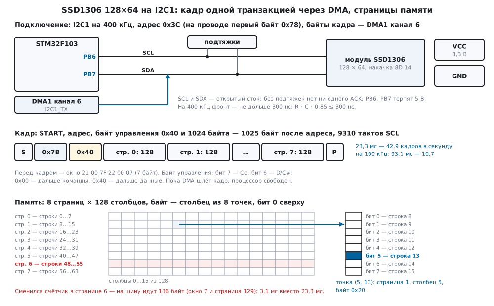
22м.1 The module, the address and the control byte
The module is 128×64 glass with an SSD1306 controller and four pins:
supply, ground, SCL and SDA. The bus address is 0x3C; 0x3D also happens
(in Zephyr 4.4.2 an SSD1306 on one of the boards is connected that way,
ssd1306@3d). According to the manufacturer's documentation the address
is selected by the SA0 pin — on modules a jumper or a resistor (not
checked).
| Module | STM32F103 | What |
|---|---|---|
| SCL, SDA | PB6, PB7 | I2C1, 400 kHz; address 0x3C |
| VCC, GND | 3.3 V and ground | common ground with the microcontroller |
PB6 and PB7 are FT (DocID13587, p. 32): if the module pull-ups go to 5 V,
the pins can take it. I2C1 is as in 22и.2: 36 MHz / (3 × 30) = 400 kHz,
TRISE = 11 (RM0008, pp. 783–784). Here also the data register address for
DMA: the I2C1_TX request goes to DMA1 channel 6 (p. 281):
static void i2c1_init(void)
{
    I2C1->CR1 = 0;                                      /* настраивать при PE = 0 */
    I2C1->CR2 = APB1_MHZ;
    I2C1->CCR = I2C_CCR_FS | 30u;                       /* DUTY = 0: 36 МГц / (3 × 30) = 400 кГц */
    I2C1->TRISE = APB1_MHZ * 300u / 1000u + 1u;         /* 300 нс × 36 МГц = 10,8 → 10 + 1 = 11 */
    I2C1->CR1 = I2C_CR1_PE;
    DMA1_Channel6->CPAR = (uint32_t)&I2C1->DR;          /* I2C1_TX — канал 6 DMA1 */
    NVIC_EnableIRQ(DMA1_Channel6_IRQn);
}
The control byte. After the address the controller expects not a
command but a control byte. Bit 7 is Co, bit 6 is D/C#. With Co = 0 this
byte is the only one for the whole transaction: 0x00 — commands only until
STOP, 0x40 — only data into memory. With Co = 1 a new control byte follows
after one byte: 0x80 — one command, 0xC0 — one data byte. That is how
Zephyr describes these four values; openmv sends commands one at a time
with 0x80 and data with 0x40. The model parses both kinds: the transaction
80 8D 80 14 80 AF C0 FF 00 20 02 gave the commands 8D:14, AF, one data
byte 0xFF into column 0 and the command 20:02. The driver in this section
uses only 0x00 and 0x40: one transaction is either commands one after
another or one frame in a row; 0x80 before every byte would double the
traffic.
The address on the wire. The first byte on the wire is the address shifted left by one bit plus the direction bit: 0x3C gives 0x78. Hence two kinds of mistake. Take 0x78 from a module description as a 7-bit address — the first byte sent is 0xF0, and that is the 10-bit address header 11110xx0 (RM0008, pp. 755 and 759): no answer. Give 0x3C to a function that expects an already shifted address (that is how HAL works: the address must be shifted left before the call) — 0x3C goes on the wire, i.e. the 7-bit 0x1E. The driver in this section takes 7 bits and shifts itself:
| Call | First byte on the wire | Result in the model |
|---|---|---|
oled_init(…, 0x3C, …) |
0x78 | OLED_OK, 4 transactions |
oled_init(…, 0x78, …) — 8 bits instead of 7 |
0xF0 | OLED_E_NACK |
| 0x3C into a function that expects 8 bits | 0x3C | OLED_E_NACK |
| module at 0x3D, driver at 0x3C | 0x78 | OLED_E_NACK |
22м.2 Initialisation: from "off" to "on"
The command order is as in Klipper: display off, clock, multiplex, offset, start line, charge pump, addressing mode, column and row flip, COM layout, contrast, precharge and VCOMH, show the memory without inversion. All of it is one transaction: the byte 0x00 and 24 bytes of commands with parameters.
/* Инициализация SSD1306 — одной транзакцией команд: выключить, частота, мультиплекс, смещение, стартовая
 * строка, накачка, горизонтальный режим, переворот сегментов и строк, раскладка COM, контраст, заряд,
 * VCOMH, показ памяти, без инверсии. Включение (0xAF) — отдельно, когда память уже очищена. */
static const uint8_t init_ssd1306[] = {
    SSD_DISPLAY_OFF, SSD_CLOCK_DIV, 0x80, SSD_MULTIPLEX, OLED_H - 1u, SSD_OFFSET, 0x00, SSD_START_LINE | 0u,
    SSD_CHARGE_PUMP, SSD_PUMP_ON, SSD_MEM_MODE, SSD_MODE_HORIZ, SSD_SEG_REMAP, SSD_COM_DEC, SSD_COM_PINS, 0x12,
    SSD_CONTRAST, 0x80, SSD_PRECHARGE, 0xF1, SSD_VCOM, 0x20, SSD_RAM_ON, SSD_NORMAL,
};
What each pair means:
| Command | Parameter | What |
|---|---|---|
AE |
— | display off until everything is set up |
D5 |
80 |
oscillator frequency and divider (as in Klipper, openmv and Zephyr) |
A8 |
3F |
64 rows: height minus 1 |
D3 |
00 |
no row shift |
40 |
— | start line 0 |
8D |
14 |
charge pump on; 10 — off, the glass is powered externally |
20 |
00 |
horizontal addressing mode (22м.3) |
A1, C8 |
— | column 127 on SEG0, rows bottom to top: this is how the module shows the picture upright |
DA |
12 |
COM layout for 128×64; for 128×32 — 02 |
81 |
80 |
contrast 128 — the Zephyr default |
D9, DB |
F1, 20 |
precharge with the internal pump (openmv, Betaflight) and VCOMH (Zephyr) |
A4, A6 |
— | show the memory, no inversion |
Switching on (AF) is not in the list. The memory after power-up is
garbage (according to the manufacturer's documentation; 4122 lit pixels out
of 8192 in the model), and switching the display on before clearing means
showing that garbage for a moment. So oled_init first sends zeros into
the whole frame and only then AF:
int oled_init(oled_t *o, uint8_t addr7, uint8_t kind, uint8_t col0)
{
    static const uint8_t on = SSD_DISPLAY_ON;
    int rc;
    o->addr = addr7;
    o->kind = kind;
    o->col0 = col0;
    o->hold = 0;
    o->xfers = o->bytes = o->errors = 0;
    o->tx[0] = OLED_CTL_DATA;
    if (kind == OLED_SH1106)
        rc = cmds(o, init_sh1106, sizeof init_sh1106);
    else
        rc = cmds(o, init_ssd1306, sizeof init_ssd1306);
    if (rc != OLED_OK)
        return rc;
    oled_clear(o);                      /* память после включения — мусор: сначала ноль, потом показ */
    if ((rc = oled_flush_all(o)) != OLED_OK)
        return rc;
    return cmds(o, &on, 1);
}
In the model oled_init took four transactions — commands (25 bytes),
window (7), a frame of zeros (1025) and AF (2), 1059 bytes in total and
24.0 ms at 400 kHz. At the moment of AF 0 pixels were lit on the glass;
switch the display on right after 8D 14 and all 4122 garbage pixels
light up.
The charge pump. OLED glass needs its own voltage, higher than the
logic supply (according to the manufacturer's documentation, not checked);
in the SSD1306 it is made by its own charge pump, switched on by the pair
8D 14 (Betaflight says it directly: 0x10 — external supply, 0x14 — the
internal converter). Without it everything else works: commands go
through, the memory is written, AF is accepted — and the glass is black.
In the model, initialisation without 8D 14: the memory matched the
reference (1484 pixels), the glass showed 0; one transaction 00 8D 14
after that lit all 1484, with 0 differences from the reference.
22м.3 The memory: 8 pages, a bit is a pixel, addressing modes
The frame memory is 8 pages of 128 bytes. A page is a band of 8 rows, a byte is a column of that band, the least significant bit is the top pixel (in Zephyr: "8 pixels vertically in a byte", and the MSB is not first). Pixel (x, y) lives in page y / 8, column x, bit y % 8:
| Pixel | Page | Column | Byte |
|---|---|---|---|
| (0, 0) | 0 | 0 | 0x01 |
| (5, 13) | 1 | 5 | 0x20 |
| (64, 33) | 4 | 64 | 0x02 |
| (127, 63) | 7 | 127 | 0x80 |
The driver lit each pixel alone on a clear screen; the model memory then held exactly one non-zero byte — the one in the table, and exactly that pixel lit on the glass.
Addressing modes decide where the next data byte goes. In horizontal
mode (20 00) the pointer runs over the window columns, at the end of a
window row it moves to the next page, after the last one back to the first.
The window is set by 21 (columns from and to) and 22 (pages from and
to). In vertical mode (20 01) it is the other way round: over the pages,
then the next column. In page mode (20 02) the pointer runs over the
columns of one page, and the page is selected by B0…B7; the column is
set by two commands, one nibble each, 0x and 1x. The model sent the
same 1024 bytes of the test frame in three modes:
| Mode | Differences from the reference | Lit pixels |
|---|---|---|
| horizontal, window 0…127 × 0…7 | 0 | 1484 |
| vertical, same window | 2294 | 1484 |
| page, page 0 | 3902 | 3794 |
In vertical mode the bytes are the same but land in the wrong places. In
page mode all 1024 bytes went round and round into page 0, and the other
seven pages kept the power-up garbage. The frame buffer in this section is
laid out page after page — exactly how horizontal mode reads it, so the
driver sets 20 00, and the frame goes out in one piece. Page mode is
needed where there is nothing else — in the SH1106 (22м.6).
22м.4 The frame buffer, a pixel and the 5×7 font
The buffer is 1024 bytes of RAM: 5 % of the 20 Kbytes of an F103C8 (DocID13587, p. 1). In 22з the frame was 40960 bytes and did not fit in RAM; here it fits entirely, and you can draw any way you like: the display sees only the finished frame. The driver keeps one more byte in front of the buffer — 0x40, so that the frame with its control byte lies in one piece (22м.5).
/* Точка (x, y): страница y / 8, столбец x, бит y % 8 — младший бит сверху */
void oled_pixel(oled_t *o, int x, int y, int on)
{
    uint8_t *b, m;
    if (x < 0 || y < 0 || x >= (int)OLED_W || y >= (int)OLED_H)
        return;
    (void)oled_wait(o);
    b = &OLED_FBP(o)[(uint32_t)(y >> 3) * OLED_W + (uint32_t)x];
    m = (uint8_t)(1u << (y & 7));
    if (!!(*b & m) == !!on)
        return;                         /* не изменилась — страница не «грязная» */
    *b ^= m;
    o->dirty |= (uint8_t)(1u << (y >> 3));
}
A pixel marks its page only if the bit really changed: lighting a pixel that is already lit is no reason to send the page.
The font is the same 5×7 array as in 22з: a character is 5 column bytes, bit 0 is the top row, from space to "Z". A character column is a ready page byte. If a text line sits on a page boundary (y is a multiple of 8), a column goes in as one byte. If not, it is split into the tails of two neighbouring pages:
/* 8 точек столбца x начиная со строки y: при y % 8 = 0 — один байт, иначе — хвосты двух соседних страниц */
static void put_col(oled_t *o, int x, int y, uint8_t bits)
{
    int p = y >> 3, sh = y & 7;
    uint8_t *fb = OLED_FBP(o);
    if (x < 0 || x >= (int)OLED_W || y < 0 || y >= (int)OLED_H)
        return;
    for (int k = 0; k < 2 && p + k < (int)OLED_PAGES; k++) {
        uint8_t m = (uint8_t)(k ? 0xFFu >> (8 - sh) : 0xFFu << sh);
        uint8_t v = (uint8_t)(k ? bits >> (8 - sh) : bits << sh);
        uint8_t *b = &fb[(uint32_t)(p + k) * OLED_W + (uint32_t)x];
        if (!m)
            break;
        if ((*b & m) != v) {
            *b = (uint8_t)((*b & ~m) | v);
            o->dirty |= (uint8_t)(1u << (p + k));
        }
    }
}
/* Строка шрифтом 5×7 в клетках 6×8: клетка пишется целиком вместе с фоном — старый знак стирать не надо */
int oled_text(oled_t *o, int x, int y, const char *s)
{
    (void)oled_wait(o);
    for (; *s; s++, x += 6) {
        char c = *s >= ' ' && *s <= 'Z' ? *s : ' ';
        for (int i = 0; i < 6; i++)
            put_col(o, x + i, y, i < 5 ? font5x7[c - ' '][i] : 0);
    }
    return x;
}
A character cell is 6×8 pixels and is written whole, background included,
so the old character need not be erased. Here is a piece of the test
screen — the start of the text "Y 27: PAGES 3-4" at y = 27 (columns 0…39, # — the pixel
is lit; column 0 is the frame):
y=24 стр.3 |#.......................................|
y=25 стр.3 |#.......................................|
y=26 стр.3 |#.......................................|
y=27 стр.3 |#...#...#........###..#####.............|
y=28 стр.3 |#...#...#.......#...#.....#..##.........|
y=29 стр.3 |#....#.#............#....#...##.........|
y=30 стр.3 |#.....#............#....#...............|
y=31 стр.3 |#.....#...........#....#.....##.........|
y=32 стр.4 |#.....#..........#.....#.....##.........|
y=33 стр.4 |#.....#.........#####..#................|
y=34 стр.4 |#.......................................|
y=35 стр.4 |#.......................................|
y=36 стр.4 |#.......................................|
y=37 стр.4 |#.......................................|
y=38 стр.4 |#.......................................|
y=39 стр.4 |#.......................................|
Rows 27…31 lie in page 3, rows 32 and 33 in page 4. For such a text line both pages become dirty.
The test picture — a frame, four text lines (three of them off a page boundary), a bar in a box — gave 1484 lit pixels on the model glass, 0 differences from the Python reference, and the controller memory matched the buffer byte for byte.
22м.5 A frame in one transaction via DMA: how long it takes
A byte on I2C is 9 SCL clocks: 8 bits and the acknowledge. A frame is the
control byte and 1024 bytes, 1025 × 9 = 9225 clocks: 92.25 ms at 100 kHz
(10.8 frames per second), 23.06 ms at 400 kHz (43.4). The model counts more
precisely: START, the address and STOP as well, and before the frame the
window 21 00 7F 22 00 07 in a separate transaction:
/* Окно для страниц p…q: SSD1306 — горизонтальный режим, столбцы и страницы от и до (7 байт);
 * SH1106 — только страничный: страница и столбец col0 тетрадами (4 байта), на каждую страницу своё окно */
static int window(oled_t *o, uint8_t p, uint8_t q)
{
    uint8_t c[6];
    if (o->kind == OLED_SH1106) {
        c[0] = (uint8_t)(SSD_PAGE_START | p);
        c[1] = (uint8_t)(SSD_COL_LOW | (o->col0 & 0x0Fu));
        c[2] = (uint8_t)(SSD_COL_HIGH | (o->col0 >> 4));
        return cmds(o, c, 3);
    }
    c[0] = SSD_COL_ADDR;
    c[1] = o->col0;
    c[2] = (uint8_t)(o->col0 + OLED_W - 1u);
    c[3] = SSD_PAGE_ADDR;
    c[4] = p;
    c[5] = q;
    return cmds(o, c, 6);
}
| What | Transactions | Bytes | SCL clocks | 400 kHz | 100 kHz |
|---|---|---|---|---|---|
| whole frame: window and 1025 bytes | 2 | 1032 | 9310 | 23.295 ms, 42.9 fps | 93.120 ms, 10.7 fps |
| whole frame byte by byte: a window and a byte each | 2048 | 9216 | 105472 | 304.620 ms, 3.3 fps | 1095.660 ms, 0.9 fps |
| one page: window and 129 bytes | 2 | 136 | 1246 | 3.135 ms | 12.480 ms |
| two neighbouring pages | 2 | 264 | 2398 | 6.015 ms | 24.000 ms |
| pages 0 and 7 | 4 | 272 | 2492 | 6.290 ms | 24.980 ms |
The time runs from the first START to the last STOP, with 20 µs of program between transactions (a model assumption). Byte by byte means 9 times more bytes and 13 times longer: every byte has its own START, address, control byte and window.
One piece of memory. For DMA to send the frame in one transfer, the
control byte and the frame must lie together. So the buffer in oled_t is
tx[1 + 1024]: tx[0] = 0x40, then pages 0…7. For pages from the 1st on,
the byte in front of them is the last byte of the previous page; for the
duration of the transfer the driver puts 0x40 there, and oled_wait puts
it back after DMA ends:
/* Страницы p…q одной транзакцией через DMA. Перед данными нужен байт 0x40: для страницы 0 это tx[0], для
 * остальных — последний байт предыдущей страницы; на время передачи в нём 0x40, oled_wait вернёт его. */
static int send_pages(oled_t *o, uint8_t p, uint8_t q)
{
    uint8_t *start = o->tx + (uint32_t)p * OLED_W;
    uint32_t n = 1u + (uint32_t)(q - p + 1u) * OLED_W;
    int rc;
    o->held = *start;
    *start = OLED_CTL_DATA;
    o->hold = start;
    rc = oled_port_dma(o->addr, start, n);
    o->xfers++;
    o->bytes += n;
    if (rc != OLED_OK) {                /* не запустилась: ждать нечего */
        *start = o->held;
        o->hold = 0;
        o->errors++;
    }
    return rc;
}
The check in the model: column 127 of page 2 was fully lit (byte 0xFF),
then only page 3 changed — 2 transactions and 136 bytes went on the bus,
and the transfer started from that very byte. After it oled_get(127, 23)
returned 1, and the next full frame matched the reference: 0 differences.
DMA on the F103. Channel 6, memory → I2C_DR, memory increment, bytes;
CNDTR holds up to 65535 (RM0008, p. 286), the frame needs 1025. Per
RM0008 (p. 769) the channel and the DMAEN bit (p. 775) are prepared before
the ADDR event; after the end of the transfer the DMA requests are
disabled, BTF is awaited, and only then STOP:
/* Передача через DMA (RM0008, с. 769): канал готов и DMAEN стоит до события ADDR; дальше на каждый TXE
 * DMA сам кладёт байт в I2C_DR. Конец ловит прерывание канала. */
int oled_port_dma(uint8_t addr7, const uint8_t *tx, uint32_t n)
{
    int rc;
    DMA1_Channel6->CCR = 0;
    DMA1_Channel6->CMAR = (uint32_t)tx;
    DMA1_Channel6->CNDTR = n;                           /* до 65 535; кадр — 1025 */
    DMA1_Channel6->CCR = DMA_CCR6_MINC | DMA_CCR6_DIR | DMA_CCR6_TCIE | DMA_CCR6_PL_1;  /* память → I2C_DR */
    I2C1->CR2 |= I2C_CR2_DMAEN;
    dma_rc = OLED_OK;
    dma_busy = 1;
    DMA1_Channel6->CCR |= DMA_CCR6_EN;
    if ((rc = start_addr(addr7)) != OLED_OK) {
        DMA1_Channel6->CCR = 0;
        I2C1->CR2 &= (uint16_t)~I2C_CR2_DMAEN;
        dma_busy = 0;
        return fail(rc);
    }
    return OLED_OK;
}
/* DMA отдал последний байт: снять запросы DMA, дождаться BTF и только потом STOP (RM0008, с. 769) */
void DMA1_Channel6_IRQHandler(void)
{
    DMA1->IFCR = DMA_IFCR_CTCIF6;
    DMA1_Channel6->CCR &= (uint16_t)~DMA_CCR6_EN;
    I2C1->CR2 &= (uint16_t)~I2C_CR2_DMAEN;
    while (!(I2C1->SR1 & (I2C_SR1_BTF | I2C_SR1_AF))) {
    }
    if (I2C1->SR1 & I2C_SR1_AF) {
        dma_rc = OLED_E_NACK;
        I2C1->SR1 = (uint16_t)~I2C_SR1_AF;
    }
    I2C1->CR1 |= I2C_CR1_STOP;
    dma_busy = 0;
}
While a frame goes out at 400 kHz, a 72 MHz core has about 1660500
cycles, at 100 kHz 6642000: with TXE polling all of that would go into
waiting. oled_flush returns right after starting DMA; the next buffer
edit (oled_pixel, oled_text) calls oled_wait itself and waits for the
end. Waiting for BTF in the interrupt lasts while the last bytes go out —
on the order of two bytes on the bus, 45 µs at 400 kHz.
22м.6 Dirty pages, contrast and burn-in, the SH1106
Send only what changed. oled_t has a dirty byte, one bit per page.
oled_flush walks the pages; consecutive dirty ones go out with one
window and one transaction:
/* «Грязные» страницы: у SSD1306 подряд идущие — одним окном и одной транзакцией, у SH1106 — по одной */
int oled_flush(oled_t *o)
{
    int rc = OLED_OK;
    uint8_t p = 0;
    while (p < OLED_PAGES) {
        uint8_t q = p;
        if (!(o->dirty & (1u << p))) {
            p++;
            continue;
        }
        if (o->kind != OLED_SH1106)
            while (q + 1u < OLED_PAGES && (o->dirty & (1u << (q + 1u))))
                q++;
        if ((rc = window(o, p, q)) != OLED_OK || (rc = send_pages(o, p, q)) != OLED_OK)
            return rc;
        o->dirty &= (uint8_t)~(((1u << (q + 1u)) - 1u) & ~((1u << p) - 1u));
        p = (uint8_t)(q + 1u);
    }
    return rc;
}
The "N:0000" counter on the test screen sits at y = 52 — pages 6 and 7.
Each new number is 2 transactions and 264 bytes instead of 1032, at
400 kHz 6.015 ms instead of 23.295; after every step the picture matched
the reference. Writing the same text again dirties no pages at all:
oled_flush sends nothing. A counter in one page (y = 48) is 136 bytes and
3.135 ms, 7.4 times faster than a full frame.
Contrast is 81 and a byte 0…255, one transaction of 3 bytes. Zephyr
uses 128 by default, Klipper 239. AE blanks the display, the memory and
settings stay: in the model after AE the glass shows 0 pixels, after
AF the picture again without a single difference.
Burn-in. An OLED pixel that is lit longer than its neighbours grows dimmer over time (according to the manufacturers' documentation, not checked; the model does not compute the burn-in rate). The model counts something else — the hours each pixel is lit per day. A "12:34" clock was updated every 10 min:
| How to show | Pixels lit | Most, h | Pixels over 20 h | Pixels over 12 h |
|---|---|---|---|---|
| in place for a day | 60 | 24.0 | 60 | 60 |
| shifted in a 3×3 circle by a pixel every 10 min | 219 | 16.0 | 0 | 14 |
in place, off for 8 h at night (AE) |
60 | 16.0 | 0 | 60 |
A shift by one or two pixels is barely visible, yet the busiest pixel is lit 16 h instead of 24, and the light is spread over 219 pixels. Lower contrast and switching off at night are the second and third ways.
The SH1106 — similar but different. The SH1106 is another controller
that can be found on a module that looks the same; Zephyr, Klipper and QMK
support it next to the SSD1306. It understands most of the same commands,
but (per Zephyr, Klipper and QMK) it has 132 columns, and the 128-pixel
glass shows columns from the 2nd (in Zephyr segment-offset = <2>), there
is no horizontal mode — page mode only, and instead of the 8D 14 charge
pump it has the AD 8B converter. The driver in this section sends each
page separately for the SH1106: B0+p, column 2 in nibbles (02 10) and
129 bytes. A frame is 16 transactions, 1064 bytes, 24.680 ms at 400 kHz
(40.5 fps) and 97.820 ms at 100 kHz (10.2).
| Module on the SH1106, driver | Differences from the reference | What the glass shows |
|---|---|---|
| for the SH1106, column 2 | 0 | the picture |
| for the SSD1306 | 3865 | garbage, at the top a scrap of the frame with shifted rows |
| for the SH1106, column 0 | 998 | the picture shifted 2 pixels left, 2 columns of garbage on the right |
The SSD1306 driver on an SH1106 is a trap. The SH1106 does not know 20,
21, 22 and 8D and (in the model) reads their parameters as new
commands: 7F from the window became start line 63, 14 from the charge
pump became the high column nibble. The 1025-byte frame went round and
round into one page, the other seven kept the power-up garbage.
22м.7 Pitfalls
The screen is black, but the exchange has no errors. The charge pump
is not on: no 8D 14. Every ACK is there, the memory is written, AF is
accepted — but there is nothing to light the glass with. In the model: 1484
pixels in memory, 0 on the glass.
No answer to a single byte. The address 0x78 (8 bits from the module
description) was given as 7-bit — 0xF0 on the wire, the 10-bit address
header. Or the other way round: 0x3C was given to a function that expects a
shifted address — the 7-bit 0x1E on the wire. Or the module was switched to
0x3D. In all three cases oled_init returned OLED_E_NACK on the first
transaction.
Works at 100 kHz, fails at 400 kHz. The pull-ups are too weak for fast mode. The rise from 0.3 to 0.7 of the supply lasts R · C · ln(0.7 / 0.3) = 0.8473 · R · C, and in fast mode it must not exceed 300 ns, in standard mode 1000 ns (DocID13587, p. 69):
| Pull-up | 50 pF | 100 pF | 200 pF |
|---|---|---|---|
| 2.2 kΩ | 93 ns | 186 ns | 373 ns — 100 kHz only |
| 4.7 kΩ | 199 ns | 398 ns — 100 kHz only | 796 ns — 100 kHz only |
| 10 kΩ | 424 ns — 100 kHz only | 847 ns — 100 kHz only | 1695 ns — neither |
With 100 pF on the line a pull-up for 400 kHz must be no more than 3541 Ω. The line capacitance is the wires, the module and the inputs; the module often already has pull-ups, and together with your own they are in parallel.
The picture is upside down or mirrored. A0/C0 instead of A1/C8
— or the module is assembled differently. In the model A0 alone gave a
mirror (0 differences from the mirrored reference, 1376 from the upright
one), A0 and C0 together a 180° rotation (1988 differences from the
upright one, 0 from the rotated one). Change the pair to suit the module,
leave the buffer alone.
The picture skips every other row, stretched vertically. The COM
layout does not match the glass: DA 02 (from a 128×32 module) was written
to a 128×64 module. In the model — 1724 differences from the reference;
DA 12 brought the picture back.
A flash of garbage at power-up. AF before clearing the memory: in
the model 4122 pixels out of 8192 are lit. The driver sends AF last,
after a frame of zeros.
The module looks the same, but the screen shows garbage and a scrap of the picture at the top. It is an SH1106 and the driver is for the SSD1306: 3865 differences. For the SH1106 — page by page and from column 2; from column 0 the picture moves 2 pixels left, and 2 columns of garbage remain on the right.
The picture briefly breaks if you draw during DMA. DMA is reading the
buffer, and the byte in front of the window holds 0x40. Every drawing
function starts with oled_wait — the edit waits for the transfer to
end.
Noise from the charge pump. The display charge pump works in pulses and draws current from 3.3 V in bursts; on the same supply line this shows as ripple. The ADC and sensitive sensors are better powered separately or decoupled. The model does not compute this, and there are no numbers here.
A 5 V module. If the module is powered from 5 V and the pull-ups are on it, SCL and SDA rise to 5 V. PB6 and PB7 are FT, they do not mind (DocID13587, p. 32); a non-FT pin on the same bus is another matter. It is simpler to power the module from 3.3 V.
22м.8 Summary
- SSD1306 over I2C: address 0x3C (or 0x3D), 0x78 on the wire; after the
address a control byte: 0x00 — commands, 0x40 — data, 0x80 — one byte.
0x78 as 7-bit is a 10-bit address header and
OLED_E_NACK. - Initialisation is one 25-byte transaction; the
8D 14charge pump is mandatory: without it 1484 pixels in memory, 0 on the glass.AFcomes after clearing, otherwise 4122 garbage pixels. - The memory is 8 pages × 128 bytes, a byte is a column, bit 0 on top: pixel (5, 13) is page 1, column 5, byte 0x20. Horizontal mode reads the buffer as it lies: 0 differences; vertical — 2294, page — 3902.
- The frame buffer is 1024 bytes (5 % of the F103C8 RAM) plus a 0x40 byte in front of it: the frame goes out in one DMA transfer, channel 6, 1025 bytes.
- A frame: 1025 × 9 = 9225 clocks — 23.06 ms (43.4 fps) at 400 kHz and 92.25 ms (10.8) at 100 kHz; with the window, address and pauses — 23.295 ms (42.9) and 93.120 ms (10.7). Byte by byte — 304.620 ms.
- Dirty pages: one is 136 bytes and 3.135 ms, 7.4 times faster than a frame; two neighbouring ones are 264 bytes in one transaction.
- Burn-in: a day in place — 60 pixels at 24 h each; a 3×3 shift — the busiest pixel 16.0 h.
- SH1106: 132 columns, offset 2, page mode only — 16 transactions per frame; the SSD1306 driver on it — 3865 differences.
Full sources
oled22m.h — SSD1306 and SH1106 commands, the control byte, the oled_t type with the frame buffer, the port and driver prototypes.
/* oled22m.h — раздел 22м: монохромный OLED 128×64 на SSD1306 (и SH1106) по I2C без регистров микроконтроллера.
 * Драйвер говорит с дисплеем через oled_port_write / oled_port_dma / oled_port_wait: в прошивке fw22m.c их
 * делают I2C1 и DMA1 канал 6 STM32F103, в стенде qhost22m.c — строки по USART1 к модели model22m.py (QEMU).
 * Коды команд, байт управления 0x00 / 0x40 / 0x80, значения 0x14 и 0x10 для накачки, 0x12 для раскладки COM,
 * 0x80 для частоты, смещение столбца SH1106 и его «только страничный режим» сверены с драйверами Zephyr 4.4.2,
 * Klipper, QMK, openmv и IronOS на диске; даташитов SSD1306 и SH1106 в проекте нет. */
#ifndef OLED22M_H
#define OLED22M_H
#include <stdint.h>

#define OLED_ADDR      0x3Cu            /* 7 бит; второй адрес модуля — 0x3D */
#define OLED_W         128u
#define OLED_H         64u
#define OLED_PAGES     8u               /* страница — 8 строк: байт = столбец из 8 точек, бит 0 — верхняя */
#define OLED_FB        (OLED_W * OLED_PAGES)   /* 1024 байта на кадр */

/* ── байт управления: первый байт после адреса ─────────────────────────── */
#define OLED_CTL_CMD   0x00u            /* Co = 0, D/C# = 0: до STOP — только команды */
#define OLED_CTL_DATA  0x40u            /* Co = 0, D/C# = 1: до STOP — только данные в память */
#define OLED_CTL_CO    0x80u            /* Co = 1: после одного байта — снова байт управления */

/* ── команды SSD1306 ───────────────────────────────────────────────────── */
#define SSD_DISPLAY_OFF   0xAEu
#define SSD_DISPLAY_ON    0xAFu
#define SSD_CLOCK_DIV     0xD5u         /* + байт: старшая тетрада — частота генератора, младшая — делитель */
#define SSD_MULTIPLEX     0xA8u         /* + байт: строк минус 1 — 0x3F для 64 */
#define SSD_OFFSET        0xD3u         /* + байт: сдвиг строк */
#define SSD_START_LINE    0x40u         /* | 0…63: с какой строки памяти начинать */
#define SSD_CHARGE_PUMP   0x8Du         /* + байт: 0x14 — накачка включена, 0x10 — выключена */
#define SSD_PUMP_ON       0x14u
#define SSD_MEM_MODE      0x20u         /* + байт: 0x00 — горизонтальный, 0x01 — вертикальный, 0x02 — страничный */
#define SSD_MODE_HORIZ    0x00u
#define SSD_SEG_REMAP     0xA1u         /* столбец 127 — на SEG0; 0xA0 — без переворота */
#define SSD_COM_DEC       0xC8u         /* строки снизу вверх; 0xC0 — сверху вниз */
#define SSD_COM_PINS      0xDAu         /* + байт: 0x12 — 128×64, 0x02 — 128×32 */
#define SSD_CONTRAST      0x81u         /* + байт 0…255 */
#define SSD_PRECHARGE     0xD9u         /* + байт */
#define SSD_VCOM          0xDBu         /* + байт */
#define SSD_RAM_ON        0xA4u         /* показывать память; 0xA5 — все точки горят */
#define SSD_NORMAL        0xA6u         /* 0xA7 — инверсия */
#define SSD_COL_ADDR      0x21u         /* + 2 байта: окно столбцов от и до (горизонтальный и вертикальный режимы) */
#define SSD_PAGE_ADDR     0x22u         /* + 2 байта: окно страниц от и до */
#define SSD_PAGE_START    0xB0u         /* | 0…7: страница — страничный режим */
#define SSD_COL_LOW       0x00u         /* | младшая тетрада столбца — страничный режим */
#define SSD_COL_HIGH      0x10u         /* | старшая тетрада столбца */
#define SH_DCDC           0xADu         /* SH1106: + байт 0x8B — преобразователь включён (вместо 0x8D 0x14) */
#define SH_DCDC_ON        0x8Bu
#define SH_PUMP_90        0x33u         /* SH1106: напряжение накачки — так шлёт Zephyr */

enum { OLED_SSD1306 = 0, OLED_SH1106 = 1 };
enum { OLED_OK = 0, OLED_E_NACK = -1, OLED_E_BUS = -2, OLED_E_ARG = -3 };

typedef struct {
    uint8_t addr;                       /* 7 бит */
    uint8_t kind;                       /* OLED_SSD1306 или OLED_SH1106 */
    uint8_t col0;                       /* первый столбец стекла в памяти: 0 у SSD1306, 2 у SH1106 (132 столбца) */
    uint8_t dirty;                      /* бит p — страница p менялась после отправки */
    uint8_t *hold;                      /* байт перед окном DMA: на время передачи в нём 0x40 */
    uint8_t held;                       /* что в нём было */
    uint32_t xfers, bytes, errors;      /* транзакций, байт после адреса, ошибок шины */
    uint8_t tx[1 + OLED_FB];            /* tx[0] = 0x40 — байт управления, tx[1…1024] — буфер кадра */
} oled_t;

#define OLED_FBP(o) ((o)->tx + 1)

/* ── порт: в прошивке — I2C1 и DMA1, в стенде — строки к модели ──────────── */
int oled_port_write(uint8_t addr7, const uint8_t *tx, uint32_t n);   /* START, адрес, n байт, STOP — и ждать */
int oled_port_dma(uint8_t addr7, const uint8_t *tx, uint32_t n);     /* то же через DMA: запустить и вернуться */
int oled_port_wait(void);                                             /* дождаться конца DMA; код ошибки */

/* ── драйвер ─────────────────────────────────────────────────────────── */
int oled_init(oled_t *o, uint8_t addr7, uint8_t kind, uint8_t col0);
int oled_wait(oled_t *o);               /* перед правкой буфера: DMA ещё может читать его */
void oled_clear(oled_t *o);
void oled_pixel(oled_t *o, int x, int y, int on);
int oled_get(oled_t *o, int x, int y);
void oled_rect(oled_t *o, int x, int y, int w, int h, int fill);
int oled_text(oled_t *o, int x, int y, const char *s);  /* шрифт 5×7, клетка 6×8; y — любой; вернёт x после текста */
int oled_flush(oled_t *o);              /* отправить «грязные» страницы */
int oled_flush_all(oled_t *o);
int oled_contrast(oled_t *o, uint8_t v);
int oled_power(oled_t *o, int on);      /* 0xAE / 0xAF: память и настройки сохраняются */

#endif
oled22m.c — the driver: initialisation, pixel, 5×7 font, window, dirty pages and the frame over DMA, shared by the firmware and the bench.
/* oled22m.c — раздел 22м: драйвер OLED 128×64 (SSD1306, SH1106): инициализация, буфер кадра, точка, шрифт 5×7,
 * «грязные» страницы и кадр одной транзакцией через DMA. Один и тот же файл собирается в прошивку (armclang,
 * Cortex-M3) и в стенд (arm-none-eabi-gcc, QEMU): микроконтроллера он не знает, только порт oled_port_*. */
#include "oled22m.h"

/* Шрифт 5×7 — тот же, что в 22з: знак — 5 столбцов, бит 0 — верхняя строка; подряд от пробела до «Z».
 * Столбец знака ложится в страницу SSD1306 как есть: бит 0 — верхняя точка страницы. */
static const uint8_t font5x7['Z' - ' ' + 1][5] = {
    {0x00, 0x00, 0x00, 0x00, 0x00},
    {0x00, 0x00, 0x00, 0x00, 0x00},
    {0x00, 0x00, 0x00, 0x00, 0x00},
    {0x00, 0x00, 0x00, 0x00, 0x00},
    {0x00, 0x00, 0x00, 0x00, 0x00},
    {0x43, 0x33, 0x08, 0x66, 0x61},   /* % */
    {0x00, 0x00, 0x00, 0x00, 0x00},
    {0x00, 0x00, 0x00, 0x00, 0x00},
    {0x00, 0x00, 0x00, 0x00, 0x00},
    {0x00, 0x00, 0x00, 0x00, 0x00},
    {0x00, 0x00, 0x00, 0x00, 0x00},
    {0x00, 0x00, 0x00, 0x00, 0x00},
    {0x00, 0x00, 0x00, 0x00, 0x00},
    {0x00, 0x08, 0x08, 0x08, 0x00},   /* - */
    {0x00, 0x60, 0x60, 0x00, 0x00},   /* . */
    {0x40, 0x30, 0x08, 0x06, 0x01},   /* / */
    {0x3E, 0x51, 0x49, 0x45, 0x3E},   /* 0 */
    {0x00, 0x42, 0x7F, 0x40, 0x00},   /* 1 */
    {0x42, 0x61, 0x51, 0x49, 0x46},   /* 2 */
    {0x21, 0x41, 0x45, 0x4B, 0x31},   /* 3 */
    {0x18, 0x14, 0x12, 0x7F, 0x10},   /* 4 */
    {0x27, 0x45, 0x45, 0x45, 0x39},   /* 5 */
    {0x3C, 0x4A, 0x49, 0x49, 0x30},   /* 6 */
    {0x01, 0x71, 0x09, 0x05, 0x03},   /* 7 */
    {0x36, 0x49, 0x49, 0x49, 0x36},   /* 8 */
    {0x06, 0x49, 0x49, 0x29, 0x1E},   /* 9 */
    {0x00, 0x36, 0x36, 0x00, 0x00},   /* : */
    {0x00, 0x00, 0x00, 0x00, 0x00},
    {0x00, 0x00, 0x00, 0x00, 0x00},
    {0x00, 0x00, 0x00, 0x00, 0x00},
    {0x00, 0x00, 0x00, 0x00, 0x00},
    {0x00, 0x00, 0x00, 0x00, 0x00},
    {0x00, 0x00, 0x00, 0x00, 0x00},
    {0x7E, 0x09, 0x09, 0x09, 0x7E},   /* A */
    {0x7F, 0x49, 0x49, 0x49, 0x36},   /* B */
    {0x3E, 0x41, 0x41, 0x41, 0x22},   /* C */
    {0x7F, 0x41, 0x41, 0x22, 0x1C},   /* D */
    {0x7F, 0x49, 0x49, 0x49, 0x41},   /* E */
    {0x7F, 0x09, 0x09, 0x09, 0x01},   /* F */
    {0x3E, 0x41, 0x49, 0x49, 0x7A},   /* G */
    {0x7F, 0x08, 0x08, 0x08, 0x7F},   /* H */
    {0x00, 0x41, 0x7F, 0x41, 0x00},   /* I */
    {0x20, 0x40, 0x41, 0x3F, 0x01},   /* J */
    {0x7F, 0x08, 0x14, 0x22, 0x41},   /* K */
    {0x7F, 0x40, 0x40, 0x40, 0x40},   /* L */
    {0x7F, 0x02, 0x0C, 0x02, 0x7F},   /* M */
    {0x7F, 0x04, 0x08, 0x10, 0x7F},   /* N */
    {0x3E, 0x41, 0x41, 0x41, 0x3E},   /* O */
    {0x7F, 0x09, 0x09, 0x09, 0x06},   /* P */
    {0x3E, 0x41, 0x51, 0x21, 0x5E},   /* Q */
    {0x7F, 0x09, 0x19, 0x29, 0x46},   /* R */
    {0x46, 0x49, 0x49, 0x49, 0x31},   /* S */
    {0x01, 0x01, 0x7F, 0x01, 0x01},   /* T */
    {0x3F, 0x40, 0x40, 0x40, 0x3F},   /* U */
    {0x1F, 0x20, 0x40, 0x20, 0x1F},   /* V */
    {0x3F, 0x40, 0x38, 0x40, 0x3F},   /* W */
    {0x63, 0x14, 0x08, 0x14, 0x63},   /* X */
    {0x03, 0x04, 0x78, 0x04, 0x03},   /* Y */
    {0x61, 0x51, 0x49, 0x45, 0x43},   /* Z */
};

/* Инициализация SSD1306 — одной транзакцией команд: выключить, частота, мультиплекс, смещение, стартовая
 * строка, накачка, горизонтальный режим, переворот сегментов и строк, раскладка COM, контраст, заряд,
 * VCOMH, показ памяти, без инверсии. Включение (0xAF) — отдельно, когда память уже очищена. */
static const uint8_t init_ssd1306[] = {
    SSD_DISPLAY_OFF, SSD_CLOCK_DIV, 0x80, SSD_MULTIPLEX, OLED_H - 1u, SSD_OFFSET, 0x00, SSD_START_LINE | 0u,
    SSD_CHARGE_PUMP, SSD_PUMP_ON, SSD_MEM_MODE, SSD_MODE_HORIZ, SSD_SEG_REMAP, SSD_COM_DEC, SSD_COM_PINS, 0x12,
    SSD_CONTRAST, 0x80, SSD_PRECHARGE, 0xF1, SSD_VCOM, 0x20, SSD_RAM_ON, SSD_NORMAL,
};

/* SH1106: вместо 0x8D 0x14 — преобразователь 0xAD 0x8B, команды 0x20 нет — только страничный режим */
static const uint8_t init_sh1106[] = {
    SSD_DISPLAY_OFF, SSD_CLOCK_DIV, 0x80, SSD_MULTIPLEX, OLED_H - 1u, SSD_OFFSET, 0x00, SSD_START_LINE | 0u,
    SH_DCDC, SH_DCDC_ON, SH_PUMP_90, SSD_SEG_REMAP, SSD_COM_DEC, SSD_COM_PINS, 0x12,
    SSD_CONTRAST, 0x80, SSD_PRECHARGE, 0x22, SSD_VCOM, 0x20, SSD_RAM_ON, SSD_NORMAL,
};

int oled_wait(oled_t *o)
{
    int rc = OLED_OK;
    if (o->hold) {
        rc = oled_port_wait();
        *o->hold = o->held;             /* DMA дочитал — вернуть байт буфера на место */
        o->hold = 0;
        if (rc != OLED_OK)
            o->errors++;
    }
    return rc;
}

static int wr(oled_t *o, const uint8_t *tx, uint32_t n)
{
    int rc = oled_wait(o);
    if (rc == OLED_OK)
        rc = oled_port_write(o->addr, tx, n);
    o->xfers++;
    o->bytes += n;
    if (rc != OLED_OK)
        o->errors++;
    return rc;
}

/* n команд одной транзакцией: байт управления 0x00, дальше все байты — команды и их параметры */
static int cmds(oled_t *o, const uint8_t *c, uint32_t n)
{
    uint8_t tx[1 + sizeof init_ssd1306];
    if (n >= sizeof tx)
        return OLED_E_ARG;
    tx[0] = OLED_CTL_CMD;
    for (uint32_t i = 0; i < n; i++)
        tx[1 + i] = c[i];
    return wr(o, tx, n + 1u);
}

int oled_init(oled_t *o, uint8_t addr7, uint8_t kind, uint8_t col0)
{
    static const uint8_t on = SSD_DISPLAY_ON;
    int rc;
    o->addr = addr7;
    o->kind = kind;
    o->col0 = col0;
    o->hold = 0;
    o->xfers = o->bytes = o->errors = 0;
    o->tx[0] = OLED_CTL_DATA;
    if (kind == OLED_SH1106)
        rc = cmds(o, init_sh1106, sizeof init_sh1106);
    else
        rc = cmds(o, init_ssd1306, sizeof init_ssd1306);
    if (rc != OLED_OK)
        return rc;
    oled_clear(o);                      /* память после включения — мусор: сначала ноль, потом показ */
    if ((rc = oled_flush_all(o)) != OLED_OK)
        return rc;
    return cmds(o, &on, 1);
}

void oled_clear(oled_t *o)
{
    uint8_t *fb = OLED_FBP(o);
    (void)oled_wait(o);
    for (uint32_t i = 0; i < OLED_FB; i++)
        fb[i] = 0;
    o->dirty = 0xFF;
}

/* Точка (x, y): страница y / 8, столбец x, бит y % 8 — младший бит сверху */
void oled_pixel(oled_t *o, int x, int y, int on)
{
    uint8_t *b, m;
    if (x < 0 || y < 0 || x >= (int)OLED_W || y >= (int)OLED_H)
        return;
    (void)oled_wait(o);
    b = &OLED_FBP(o)[(uint32_t)(y >> 3) * OLED_W + (uint32_t)x];
    m = (uint8_t)(1u << (y & 7));
    if (!!(*b & m) == !!on)
        return;                         /* не изменилась — страница не «грязная» */
    *b ^= m;
    o->dirty |= (uint8_t)(1u << (y >> 3));
}

int oled_get(oled_t *o, int x, int y)
{
    (void)oled_wait(o);
    if (x < 0 || y < 0 || x >= (int)OLED_W || y >= (int)OLED_H)
        return 0;
    return OLED_FBP(o)[(uint32_t)(y >> 3) * OLED_W + (uint32_t)x] >> (y & 7) & 1;
}

void oled_rect(oled_t *o, int x, int y, int w, int h, int fill)
{
    for (int j = y; j < y + h; j++)
        for (int i = x; i < x + w; i++)
            if (fill || j == y || j == y + h - 1 || i == x || i == x + w - 1)
                oled_pixel(o, i, j, 1);
}

/* 8 точек столбца x начиная со строки y: при y % 8 = 0 — один байт, иначе — хвосты двух соседних страниц */
static void put_col(oled_t *o, int x, int y, uint8_t bits)
{
    int p = y >> 3, sh = y & 7;
    uint8_t *fb = OLED_FBP(o);
    if (x < 0 || x >= (int)OLED_W || y < 0 || y >= (int)OLED_H)
        return;
    for (int k = 0; k < 2 && p + k < (int)OLED_PAGES; k++) {
        uint8_t m = (uint8_t)(k ? 0xFFu >> (8 - sh) : 0xFFu << sh);
        uint8_t v = (uint8_t)(k ? bits >> (8 - sh) : bits << sh);
        uint8_t *b = &fb[(uint32_t)(p + k) * OLED_W + (uint32_t)x];
        if (!m)
            break;
        if ((*b & m) != v) {
            *b = (uint8_t)((*b & ~m) | v);
            o->dirty |= (uint8_t)(1u << (p + k));
        }
    }
}

/* Строка шрифтом 5×7 в клетках 6×8: клетка пишется целиком вместе с фоном — старый знак стирать не надо */
int oled_text(oled_t *o, int x, int y, const char *s)
{
    (void)oled_wait(o);
    for (; *s; s++, x += 6) {
        char c = *s >= ' ' && *s <= 'Z' ? *s : ' ';
        for (int i = 0; i < 6; i++)
            put_col(o, x + i, y, i < 5 ? font5x7[c - ' '][i] : 0);
    }
    return x;
}

/* Окно для страниц p…q: SSD1306 — горизонтальный режим, столбцы и страницы от и до (7 байт);
 * SH1106 — только страничный: страница и столбец col0 тетрадами (4 байта), на каждую страницу своё окно */
static int window(oled_t *o, uint8_t p, uint8_t q)
{
    uint8_t c[6];
    if (o->kind == OLED_SH1106) {
        c[0] = (uint8_t)(SSD_PAGE_START | p);
        c[1] = (uint8_t)(SSD_COL_LOW | (o->col0 & 0x0Fu));
        c[2] = (uint8_t)(SSD_COL_HIGH | (o->col0 >> 4));
        return cmds(o, c, 3);
    }
    c[0] = SSD_COL_ADDR;
    c[1] = o->col0;
    c[2] = (uint8_t)(o->col0 + OLED_W - 1u);
    c[3] = SSD_PAGE_ADDR;
    c[4] = p;
    c[5] = q;
    return cmds(o, c, 6);
}

/* Страницы p…q одной транзакцией через DMA. Перед данными нужен байт 0x40: для страницы 0 это tx[0], для
 * остальных — последний байт предыдущей страницы; на время передачи в нём 0x40, oled_wait вернёт его. */
static int send_pages(oled_t *o, uint8_t p, uint8_t q)
{
    uint8_t *start = o->tx + (uint32_t)p * OLED_W;
    uint32_t n = 1u + (uint32_t)(q - p + 1u) * OLED_W;
    int rc;
    o->held = *start;
    *start = OLED_CTL_DATA;
    o->hold = start;
    rc = oled_port_dma(o->addr, start, n);
    o->xfers++;
    o->bytes += n;
    if (rc != OLED_OK) {                /* не запустилась: ждать нечего */
        *start = o->held;
        o->hold = 0;
        o->errors++;
    }
    return rc;
}

/* «Грязные» страницы: у SSD1306 подряд идущие — одним окном и одной транзакцией, у SH1106 — по одной */
int oled_flush(oled_t *o)
{
    int rc = OLED_OK;
    uint8_t p = 0;
    while (p < OLED_PAGES) {
        uint8_t q = p;
        if (!(o->dirty & (1u << p))) {
            p++;
            continue;
        }
        if (o->kind != OLED_SH1106)
            while (q + 1u < OLED_PAGES && (o->dirty & (1u << (q + 1u))))
                q++;
        if ((rc = window(o, p, q)) != OLED_OK || (rc = send_pages(o, p, q)) != OLED_OK)
            return rc;
        o->dirty &= (uint8_t)~(((1u << (q + 1u)) - 1u) & ~((1u << p) - 1u));
        p = (uint8_t)(q + 1u);
    }
    return rc;
}

int oled_flush_all(oled_t *o)
{
    o->dirty = 0xFF;
    return oled_flush(o);
}

int oled_contrast(oled_t *o, uint8_t v)
{
    uint8_t c[2] = {SSD_CONTRAST, v};
    return cmds(o, c, 2);
}

int oled_power(oled_t *o, int on)
{
    uint8_t c = on ? SSD_DISPLAY_ON : SSD_DISPLAY_OFF;
    return cmds(o, &c, 1);
}
fw22m.c — STM32F103 firmware: I2C1 at 400 kHz, DMA1 channel 6, a counter on the screen every 100 ms.
/* fw22m.c — раздел 22м: OLED 128×64 на SSD1306 у STM32F103 (BluePill), 72 МГц, APB1 = 36 МГц.
 * I2C1: PB6 — SCL, PB7 — SDA (открытый сток, 400 кГц), адрес дисплея 0x3C.
 * Команды идут опросом флагов, кадр и «грязные» страницы — через DMA1 канал 6 (запрос I2C1_TX):
 * пока байты уходят по шине, процессор свободен. На экране — заголовок и счётчик; раз в 100 мс
 * меняется счётчик, и на шину уходит только его страница. Тактирование до 72 МГц — как в разделе 6. */
#include "stm32f10x.h"
#include "oled22m.h"

#define CPU_HZ          72000000u
#define APB1_MHZ        36u
#define I2C_TIMEOUT_US  1000u           /* на START, адрес и один байт команды */
#define DMA_TIMEOUT_US  50000u          /* весь кадр — 9310 тактов SCL: 23,3 мс на 400 кГц, 93,1 мс на 100 кГц */

static oled_t oled;
static volatile uint8_t dma_busy;
static volatile int dma_rc;
static volatile uint32_t ticks;
volatile uint32_t frames, bus_errors, idle_loops;

void SysTick_Handler(void)
{
    ticks++;
}

static int expired(uint32_t t0, uint32_t us)
{
    return DWT->CYCCNT - t0 >= us * (CPU_HZ / 1000000u);
}

static void clock_72mhz(void)
{
    RCC->CR |= RCC_CR_HSEON;
    while (!(RCC->CR & RCC_CR_HSERDY)) {
    }
    FLASH->ACR = FLASH_ACR_PRFTBE | FLASH_ACR_LATENCY_2;            /* 72 МГц — два такта ожидания Flash */
    RCC->CFGR = RCC_CFGR_PLLSRC | RCC_CFGR_PLLMULL9 | RCC_CFGR_PPRE1_DIV2;
    RCC->CR |= RCC_CR_PLLON;
    while (!(RCC->CR & RCC_CR_PLLRDY)) {
    }
    RCC->CFGR |= RCC_CFGR_SW_PLL;
    while ((RCC->CFGR & RCC_CFGR_SWS) != RCC_CFGR_SWS_PLL) {
    }
}

static void pins_init(void)
{
    RCC->APB2ENR |= RCC_APB2ENR_IOPBEN | RCC_APB2ENR_AFIOEN;
    RCC->APB1ENR |= RCC_APB1ENR_I2C1EN;
    RCC->AHBENR |= RCC_AHBENR_DMA1EN;
    /* PB6, PB7 — альтернативная функция, открытый сток, 50 МГц (1111); подтяжки — на модуле или свои */
    GPIOB->CRL = (GPIOB->CRL & 0x00FFFFFFu) | 0xFF000000u;
}

static void i2c1_init(void)
{
    I2C1->CR1 = 0;                                      /* настраивать при PE = 0 */
    I2C1->CR2 = APB1_MHZ;
    I2C1->CCR = I2C_CCR_FS | 30u;                       /* DUTY = 0: 36 МГц / (3 × 30) = 400 кГц */
    I2C1->TRISE = APB1_MHZ * 300u / 1000u + 1u;         /* 300 нс × 36 МГц = 10,8 → 10 + 1 = 11 */
    I2C1->CR1 = I2C_CR1_PE;
    DMA1_Channel6->CPAR = (uint32_t)&I2C1->DR;          /* I2C1_TX — канал 6 DMA1 */
    NVIC_EnableIRQ(DMA1_Channel6_IRQn);
}

static int sr1_wait(uint16_t mask)
{
    uint32_t t0 = DWT->CYCCNT;
    while (!(I2C1->SR1 & mask)) {
        if (I2C1->SR1 & I2C_SR1_AF)
            return OLED_E_NACK;                         /* адрес или байт не подтверждён */
        if (expired(t0, I2C_TIMEOUT_US))
            return OLED_E_BUS;
    }
    return OLED_OK;
}

static int fail(int rc)
{
    I2C1->CR1 |= I2C_CR1_STOP;
    I2C1->SR1 = (uint16_t)~I2C_SR1_AF;                  /* AF снимается записью нуля */
    return rc;
}

/* START и адрес на запись: после чтения SR2 (ADDR снят) шина ждёт первый байт */
static int start_addr(uint8_t addr7)
{
    int rc;
    uint32_t t0 = DWT->CYCCNT;
    while (I2C1->SR2 & I2C_SR2_BUSY) {                  /* SDA держит ведомый — раздел 17.6 */
        if (expired(t0, I2C_TIMEOUT_US))
            return OLED_E_BUS;
    }
    I2C1->CR1 |= I2C_CR1_START;
    if ((rc = sr1_wait(I2C_SR1_SB)) != OLED_OK)
        return rc;
    I2C1->DR = (uint8_t)(addr7 << 1);                   /* 7-битный 0x3C на проводе — 0x78 */
    if ((rc = sr1_wait(I2C_SR1_ADDR)) != OLED_OK)
        return rc;
    (void)I2C1->SR2;
    return OLED_OK;
}

int oled_port_write(uint8_t addr7, const uint8_t *tx, uint32_t n)
{
    int rc = start_addr(addr7);
    for (uint32_t i = 0; rc == OLED_OK && i < n; i++)
        if ((rc = sr1_wait(I2C_SR1_TXE)) == OLED_OK)
            I2C1->DR = tx[i];
    if (rc == OLED_OK)
        rc = sr1_wait(I2C_SR1_BTF);
    if (rc != OLED_OK)
        return fail(rc);
    I2C1->CR1 |= I2C_CR1_STOP;
    return OLED_OK;
}

/* Передача через DMA (RM0008, с. 769): канал готов и DMAEN стоит до события ADDR; дальше на каждый TXE
 * DMA сам кладёт байт в I2C_DR. Конец ловит прерывание канала. */
int oled_port_dma(uint8_t addr7, const uint8_t *tx, uint32_t n)
{
    int rc;
    DMA1_Channel6->CCR = 0;
    DMA1_Channel6->CMAR = (uint32_t)tx;
    DMA1_Channel6->CNDTR = n;                           /* до 65 535; кадр — 1025 */
    DMA1_Channel6->CCR = DMA_CCR6_MINC | DMA_CCR6_DIR | DMA_CCR6_TCIE | DMA_CCR6_PL_1;  /* память → I2C_DR */
    I2C1->CR2 |= I2C_CR2_DMAEN;
    dma_rc = OLED_OK;
    dma_busy = 1;
    DMA1_Channel6->CCR |= DMA_CCR6_EN;
    if ((rc = start_addr(addr7)) != OLED_OK) {
        DMA1_Channel6->CCR = 0;
        I2C1->CR2 &= (uint16_t)~I2C_CR2_DMAEN;
        dma_busy = 0;
        return fail(rc);
    }
    return OLED_OK;
}

/* DMA отдал последний байт: снять запросы DMA, дождаться BTF и только потом STOP (RM0008, с. 769) */
void DMA1_Channel6_IRQHandler(void)
{
    DMA1->IFCR = DMA_IFCR_CTCIF6;
    DMA1_Channel6->CCR &= (uint16_t)~DMA_CCR6_EN;
    I2C1->CR2 &= (uint16_t)~I2C_CR2_DMAEN;
    while (!(I2C1->SR1 & (I2C_SR1_BTF | I2C_SR1_AF))) {
    }
    if (I2C1->SR1 & I2C_SR1_AF) {
        dma_rc = OLED_E_NACK;
        I2C1->SR1 = (uint16_t)~I2C_SR1_AF;
    }
    I2C1->CR1 |= I2C_CR1_STOP;
    dma_busy = 0;
}

int oled_port_wait(void)
{
    uint32_t t0 = DWT->CYCCNT;
    while (dma_busy) {
        if ((I2C1->SR1 & I2C_SR1_AF) || expired(t0, DMA_TIMEOUT_US)) {
            int rc = I2C1->SR1 & I2C_SR1_AF ? OLED_E_NACK : OLED_E_BUS;   /* дисплей замолчал посреди кадра */
            DMA1_Channel6->CCR = 0;
            I2C1->CR2 &= (uint16_t)~I2C_CR2_DMAEN;
            dma_busy = 0;
            bus_errors++;
            return fail(rc);
        }
    }
    return dma_rc;
}

static void counter_text(char *s, uint32_t n)
{
    s[0] = 'N';
    s[1] = ':';
    for (int i = 5; i >= 2; i--, n /= 10u)
        s[i] = (char)('0' + n % 10u);
    s[6] = 0;
}

int main(void)
{
    char s[8];
    uint32_t last = 0, n = 0;
    clock_72mhz();
    SysTick_Config(CPU_HZ / 1000u);
    CoreDebug->DEMCR |= CoreDebug_DEMCR_TRCENA_Msk;
    DWT->CYCCNT = 0;
    DWT->CTRL |= DWT_CTRL_CYCCNTENA_Msk;
    pins_init();
    i2c1_init();
    while (oled_init(&oled, OLED_ADDR, OLED_SSD1306, 0) != OLED_OK) {
        uint32_t t0 = ticks;                            /* нет ответа: провод, подтяжки, адрес, питание */
        bus_errors++;
        while (ticks - t0 < 100u) {
        }
    }
    oled_rect(&oled, 0, 0, 128, 64, 0);
    oled_text(&oled, 4, 2, "SSD1306 128X64");
    oled_text(&oled, 4, 16, "I2C 400 KHZ  DMA");
    (void)oled_flush(&oled);                            /* весь кадр: 1025 байт одной транзакцией */
    for (;;) {
        if (ticks - last < 100u) {
            idle_loops++;                               /* шина занята DMA, а процессор свободен */
            continue;
        }
        last += 100u;
        counter_text(s, n++);
        oled_text(&oled, 4, 48, s);                     /* oled_text сам дождётся конца прошлого DMA */
        if (oled_flush(&oled) != OLED_OK)
            bus_errors++;
        frames++;
    }
}
Next: section 43 "Hardware cryptography: CRC, RNG, HASH, CRYP".