 Embedded HandbookApps
22л. The DS3231 external clock over I2C: BCD registers, alarms, the SQW interrupt, temperature compensation and aging
The built-in clock of the F103 is covered in 12.6 and in project 198: a 32-bit seconds counter driven by a watch crystal, with the calendar and the alarm left to the program and the rate trimmed by dropping pulses. The G4 clock is richer (12а). Here is another way: a separate DS3231 clock chip on I2C. When it beats the built-in clock, what sits in its 19 registers, why the time is read and written in one transaction, how the two alarms and their masks work, how to wake the microcontroller from Stop with the INT/SQW pin, what the OSF flag means, how to read the temperature sensor and trim the rate with the Aging offset register — and what breaks at each of these steps.
Sources: RM0008 (DocID13902 Rev 17): Stop — PLL, HSI and HSE are off, the
LPDS bit, p. 73; leaving Stop on HSI, entering via SLEEPDEEP,
PDDS = 0 and LPDS, with an EXTI_PR bit set Stop is not entered,
p. 74; input with pull-up, p. 160; AFIO_EXTICR3, p. 191; EXTI_FTSR,
p. 211; EXTI_PR, p. 212; I2C up to 400 kHz, p. 752; master reception,
pp. 763–764; I2C_CCR, pp. 783–784; I2C_TRISE, p. 784. DocID13587 Rev 17
(STM32F103x8/xB): PB6 is I2C1_SCL, PB7 is I2C1_SDA, both FT, p. 32; PB8
is FT, p. 33. The project has no DS3231 document. The register numbers
0x00…0x12, the CTRL and STAT bits, the 12/24 and PM bits, the century
bit, the alarm masks and the rule "only 1111, 1110, 1100, 1000 and 0000 are
valid", the DY/DT bit, the square wave frequencies, the 64 s temperature
cycle, the CONV bit, the temperature format, "setting the time restarts
the countdown", "flags are cleared with zeros, writing ones leaves them
alone", open drain on INT/SQW and 32K and the address 0x68 were checked
against the DS3231 drivers from Zephyr 4.4.2. The temperature curve of an
ordinary watch crystal is from 174.4, the F103 trim step is from 198.4, the
MPU-6050 address is from 99.1. The ±2 ppm accuracy, the Aging offset step
of about 0.1 ppm, copying the time into a buffer on START, the power-on
values, the leap year rule and the century bit toggling, 400 kHz operation
and currents follow the manufacturer's documentation and were not checked:
in the model they are assumptions. All numbers below come from running the
driver _verify/rtc22l/rtc22l.c, built with arm-none-eabi-gcc 12.2.1 for the
Cortex-M3 and run in QEMU 7.2 (stm32vldiscovery), against its own DS3231
model in Python 3.11; in the bench I2C is replaced by text lines over
USART1. The F103 firmware is built with armclang 6.24.
What it is called in the documentation
Original Meaning TCXO (temperature-compensated crystal oscillator) crystal oscillator with temperature compensation BCD (binary-coded decimal) one decimal digit per nibble 12/24, AM/PM 12- or 24-hour mode; before and after noon century bit century bit alarm mask bits A1M1…A1M4, A2M2…A2M4 "do not compare this alarm field" bits DY/DT (day / date) day of the week or day of the month INTCN, INT/SQW choice: interrupt or square wave on one pin A1IE, A2IE; A1F, A2F alarm interrupt enable; alarm flag OSF (oscillator stop flag) "the oscillator has stopped" flag EOSC (enable oscillator, active low) 1 — the oscillator stops on battery BBSQW (battery-backed square wave) square wave on battery as well EN32kHz 32 kHz output CONV, BSY measure the temperature now; a measurement is running aging offset frequency correction: rate trim VBAT battery pin
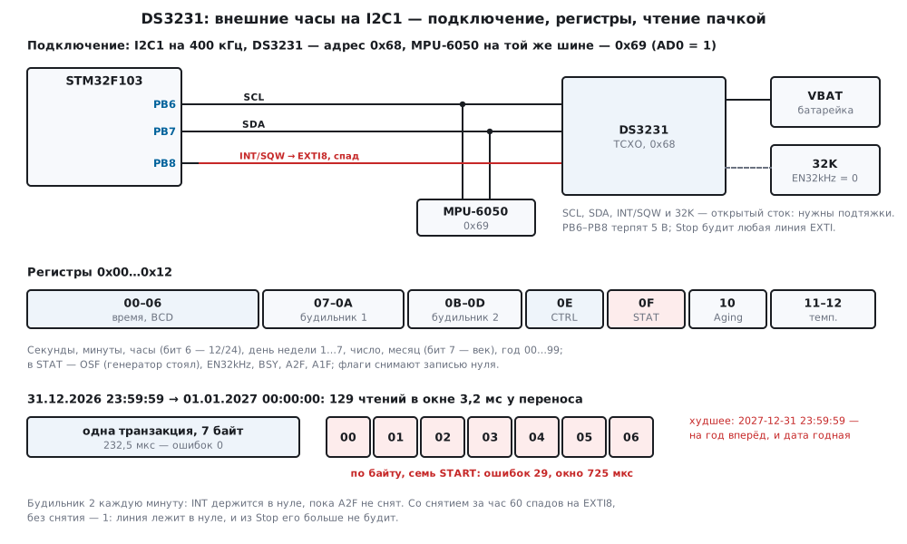
22л.1 When an external chip beats the built-in clock
The built-in clock of the F103 and the DS3231 have one job — keep running while everything else is unpowered. The difference is where the second comes from. The F103 counts the pulses of a watch crystal, whose frequency depends on temperature along a parabola: about −0.035 ppm/°C² with the vertex at 25 °C (174.4). The DS3231 measures the temperature every 64 s and trims the capacitances of its oscillator — that is how Zephyr describes the cycle; the manufacturer promises ±2 ppm (not checked). The model worked out what that means in seconds:
| Temperature | Crystal per 174.4, ppm | Per day | Per 30 days |
|---|---|---|---|
| −20 °C | −70.9 | −6.12 s | −183.7 s |
| 0 °C | −21.9 | −1.89 s | −56.7 s |
| 10 °C / 40 °C | −7.9 | −0.68 s | −20.4 s |
| 25 °C | 0 | 0 | 0 |
| 60 °C | −42.9 | −3.70 s | −111.1 s |
| DS3231, worst case ±2 ppm | ±2 | ±0.173 s | ±5.18 s |
The F103 trim (198.4) only slows the clock in steps of 0.954 ppm and removes a constant error, not the temperature one. The DS3231 has its own correction — Aging offset, in both directions (22л.6). Other arguments for an external chip: the calendar with the day of the week and two alarms with masks are kept by the chip, not by the program; its own battery — the time survives a reset, reflashing and the loss of the microcontroller backup domain (10.5). Arguments against: one more chip and a bus, reading the time is an I2C transaction (232.5 µs at 400 kHz), and there are no fractions of a second — Zephyr says outright that the clock advances one tick per second with no access to sub-second precision.
Connection. The DS3231 sits on I2C1, like the MCP23017 in 22и.2:
| DS3231 | STM32F103 | What |
|---|---|---|
| SCL, SDA | PB6, PB7 | I2C1, 400 kHz; address 0x68 |
| INT/SQW | PB8 | input with pull-up, EXTI8 on the falling edge |
| 32K | — | 32 kHz output: the driver turns it off |
| VBAT | battery | keeps time without main power |
| VCC, GND | 3.3 V and ground | common ground with the microcontroller |
INT/SQW and 32K are open drain (that is how Zephyr describes them): without
a pull-up there is no falling edge. PB6, PB7 and PB8 are FT (DocID13587,
pp. 32–33): pull-ups to 5 V will not burn them. I2C1 is as in 22и.2:
36 MHz / (3 × 30) = 400 kHz, TRISE = 11 (RM0008, pp. 783–784). PB8 is an
input with pull-up, code 1000 (p. 160), line EXTI8 is tied to port B with
the AFIO_EXTICR3 field = 0001 (p. 191), and the falling edge is enabled in
EXTI_FTSR (p. 211):
static void pins_init(void)
{
    RCC->APB2ENR |= RCC_APB2ENR_IOPBEN | RCC_APB2ENR_IOPCEN | RCC_APB2ENR_AFIOEN;
    RCC->APB1ENR |= RCC_APB1ENR_I2C1EN | RCC_APB1ENR_PWREN;
    /* PB6, PB7 — альтернативная функция, открытый сток, 50 МГц (1111) */
    GPIOB->CRL = (GPIOB->CRL & 0x00FFFFFFu) | 0xFF000000u;
    /* PB8 — вход с подтяжкой (1000): INT/SQW — открытый сток */
    GPIOB->BSRR = 1u << 8;
    GPIOB->CRH = (GPIOB->CRH & ~0xFu) | 0x8u;
    /* PC13 — выход 2 МГц (0010), светодиод горит нулём */
    GPIOC->BSRR = 1u << 13;
    GPIOC->CRH = (GPIOC->CRH & ~0x00F00000u) | 0x00200000u;
}
The DS3231 has no address pins: the address is always 0x68. The MPU-6050 with AD0 = 0 has the same address (99.1), and the two cannot share a bus — 22л.7.
22л.2 Registers 0x00…0x12: BCD, 12/24 hours and the century bit
| Number | What | Bits |
|---|---|---|
| 0x00 | seconds | BCD 00…59 |
| 0x01 | minutes | BCD 00…59 |
| 0x02 | hours | bit 6 — 12-hour mode; in it bit 5 is PM, otherwise bit 5 is the "20" ten |
| 0x03 | day of the week | 1…7; which day is first is up to the program |
| 0x04 | date | BCD 01…31 |
| 0x05 | month | BCD 01…12; bit 7 is the century bit |
| 0x06 | year | BCD 00…99 |
| 0x07…0x0A | alarm 1 | seconds, minutes, hours, day; bit 7 of each — "do not compare" |
| 0x0B…0x0D | alarm 2 | minutes, hours, day — no seconds |
| 0x0E | CTRL |
EOSC, BBSQW, CONV, RS2 RS1, INTCN, A2IE, A1IE |
| 0x0F | STAT |
OSF, EN32kHz, BSY, A2F, A1F |
| 0x10 | Aging offset | signed number |
| 0x11, 0x12 | temperature | signed whole degrees; in 0x12 bits 7:6 are quarters |
BCD. Each decimal digit is its own nibble: 59 seconds is 0x59, not 0x3B.
After setting 2026-10-27 23:59:58 (a Tuesday) the first seven registers in
the model are 58 59 23 02 27 10 26: readable by eye. Reading them as
binary is a common mistake: the seconds 0…59 turn into 60 numbers from 0 to
89 with jumps 9 → 16, 25 → 32 and so on. Writing binary is one too: 45
minutes as 0x2D is not BCD.
12 and 24 hours. The driver always writes 24-hour mode but reads both: someone else may have set the other one. In 12-hour mode bit 6 = 1, bit 5 means after noon, the hours are 1…12, and 12 AM is midnight:
/* 7 байт → время. Понимает и 12-часовой режим, если его поставил кто-то другой: 12 AM — это 0 часов. */
int rtc_from_regs(const uint8_t r[7], rtc_tm_t *t)
{
    uint8_t h = r[2];
    if (!bcd_ok(r[0] & 0x7Fu) || !bcd_ok(r[1] & 0x7Fu) || !bcd_ok(r[4] & 0x3Fu) || !bcd_ok(r[5] & 0x1Fu)
        || !bcd_ok(r[6]) || !bcd_ok(h & (h & DS_H12 ? 0x1Fu : 0x3Fu)))
        return RTC_E_RANGE;
    t->sec = bcd_dec(r[0] & 0x7Fu);
    t->min = bcd_dec(r[1] & 0x7Fu);
    if (h & DS_H12) {
        uint8_t h12 = bcd_dec(h & 0x1Fu);               /* 1…12 */
        if (h12 < 1u || h12 > 12u)
            return RTC_E_RANGE;
        t->hour = (uint8_t)(h12 % 12u + (h & DS_PM ? 12u : 0u));
    } else {
        t->hour = bcd_dec(h & 0x3Fu);
    }
    t->wday = r[3] & 7u;
    t->date = bcd_dec(r[4] & 0x3Fu);
    t->mon = bcd_dec(r[5] & 0x1Fu);
    t->year = (uint16_t)(2000u + bcd_dec(r[6]) + (r[5] & DS_CENTURY ? 100u : 0u));
    return rtc_valid(t) && t->wday >= 1u ? RTC_OK : RTC_E_RANGE;
}
In the model the chip was put into 12-hour mode and walked through all 24 hours: the driver read 24 of 24 correctly. The 11:59:59 PM rollover gave the hours register 0x52 (12 AM) and the next day — 2026-10-28 00:00:00. Other drivers do not always cope with this mode — 22л.7.
The century bit. The chip keeps two digits of the year. Bit 7 of the
month toggles when the year goes 99 → 00 (per the manufacturer's
documentation), and what it means is up to the program. In Zephyr 4.4.2 two
drivers decided differently: the counter driver reads a year without the
bit as the 1900s and with the bit as the 2000s; the rtc driver ignores the
bit and always gives 20xx (there is a FIXME there). The driver of this
section takes 2000 + year + 100 when the century bit is set:
/* Время → 7 байт с 0x00: всегда 24-часовой режим, день недели считаем сами, век — битом месяца */
void rtc_to_regs(const rtc_tm_t *t, uint8_t r[7])
{
    r[0] = bcd_enc(t->sec);
    r[1] = bcd_enc(t->min);
    r[2] = bcd_enc(t->hour);
    r[3] = rtc_wday(t->year, t->mon, t->date);
    r[4] = bcd_enc(t->date);
    r[5] = (uint8_t)(bcd_enc(t->mon) | (t->year >= 2100u ? DS_CENTURY : 0u));
    r[6] = bcd_enc((uint8_t)(t->year % 100u));
}
| Time | Seven registers |
|---|---|
| 2026-10-27 23:59:58, Tuesday | 58 59 23 02 27 10 26 |
| 2028-02-29 07:05:09, Tuesday | 09 05 07 02 29 02 28 |
| 2099-12-31 23:59:59, Thursday | 59 59 23 04 31 12 99 |
| 2100-03-01 00:00:00, Monday | 00 00 00 01 01 83 00 |
The driver computes the day of the week itself (here 1 is Monday).
rtc_valid rejects 2027-02-29.
22л.3 Time in one burst: setting and reading in one transaction
The time is seven registers, and a second can end in the middle of an exchange. Hence two rules.
Read all 7 bytes in one transaction. Per the manufacturer's
documentation (not checked) the chip copies the time into a buffer on
START, and the read comes from the buffer while counting goes on: a
rollover in the middle of the burst will not tear it. Zephyr reads the same
way — all registers in one i2c_write_read.
Write from 0x00 in one transaction. Setting the time restarts the
sub-second countdown chain — Zephyr says so; per the manufacturer's
documentation it is the write of the seconds that restarts it (not checked,
the model does so). The seconds byte goes first, and the next rollover
comes only a second later, when the other six bytes are long in place.
After writing, the driver clears OSF: the time is now valid.
/* Время — одной транзакцией с 0x00: первым ложится байт секунд, и отсчёт секунды начинается заново;
 * переноса посреди записи не будет. Потом снять OSF: время теперь верное. */
int rtc_set(rtc_t *d, const rtc_tm_t *t)
{
    uint8_t tx[8], st;
    int rc;
    if (!rtc_valid(t))
        return RTC_E_RANGE;
    tx[0] = DS_SEC;
    rtc_to_regs(t, tx + 1);
    if ((rc = wr(d, tx, 8)) != RTC_OK)
        return rc;
    if ((rc = rd(d, DS_STAT, &st, 1)) != RTC_OK)
        return rc;
    return stat_write(d, st & DS_EN32K, DS_OSF);
}
/* Все 7 байт — одной транзакцией: микросхема копирует время в буфер на START, и пока байты идут по шине,
 * перенос их не разорвёт. */
int rtc_get(rtc_t *d, rtc_tm_t *t)
{
    uint8_t r[7];
    int rc = rd(d, DS_SEC, r, 7);
    if (rc != RTC_OK)
        return rc;
    return rtc_from_regs(r, t);
}
At 400 kHz rtc_get is one transaction, 93 SCL clocks, 232.5 µs; rtc_set
is three transactions, 377.5 µs on the bus. At 100 kHz — 930 and 1510 µs.
Experiment: reading across the new year. The model set 2026-12-31 23:59:59 so that the rollover falls at a given moment and read the time starting 3 ms before the rollover up to 200 µs after it, in 25 µs steps — 129 reads. An answer was counted as good if it was "before the rollover" or "after":
| How to read | 400 kHz: errors | Window | 100 kHz: errors | Window |
|---|---|---|---|---|
one transaction, 7 bytes (rtc_get) |
0 of 129 | — | 0 of 129 | — |
| seven one-byte transactions | 29 of 129 | 725 µs | 98 of 129 | 2450 µs |
Reading byte by byte means seven STARTs and seven copies. If the rollover falls between them, the upper fields are already new and the lower ones still old: 2027-01-01 00:00:59 (59 s ahead), 2027-01-01 00:59:59 (an hour), 2027-01-01 23:59:59 (a day), 2027-01-31 23:59:59 (a month) and 2027-12-31 23:59:59 — a year. All these dates are valid, and a range check will not catch them. The window is the time from the first byte to the last: 802.5 µs for seven transactions against 232.5 for one.
Experiment: setting field by field. The old time is 2026-03-31 23:59:59, the new one 2026-05-15 12:00:00; the write started from 1.2 ms before the rollover to 100 µs after it, in 20 µs steps — 66 writes:
| How to write | Errors | Result |
|---|---|---|
rtc_set: 7 bytes from 0x00 |
0 of 66 | 2026-05-15 12:00:00 |
| field by field, from the year to the seconds | 23 of 66 | 2026-06-15 12:00:00 — 4 times; 2026-05-16 12:00:00 — 9; 13:00:00 — 5; 12:01:00 — 5 |
The month is already written (May), the date is still old (31), and the day rollover moves the chip to June 1; writing the date 15 gives June 15. The day, the hour and the minute slip the same way.
22л.4 Two alarms: the A1M1…A1M4 masks and DY/DT
Alarm 1 has seconds, minutes, hours and day (0x07…0x0A), alarm 2 has
minutes, hours and day (0x0B…0x0D): it has no seconds, its resolution is a
minute (so in Zephyr), and it fires at the start of a minute. Bit 7 of each
byte is the "do not compare this field" mask, bit 6 of the day byte is
DY/DT: 1 — day of the week 1…7, 0 — day of the month. A match sets the
A1F or A2F flag in STAT; if A1IE or A2IE is enabled and
INTCN = 1, the INT/SQW pin goes low.
Masks are set "from the top down": if a field is compared, all finer ones are compared too. Zephyr calls only 1111, 1110, 1100, 1000 and 0000 valid (in the order day, hours, minutes, seconds) and rejects the rest "for predictable behavior"; so does the driver:
/* Будильник n (1 или 2): байты — одной транзакцией, старый флаг снять, потом разрешить AxIE */
int rtc_alarm_set(rtc_t *d, uint8_t n, const rtc_alarm_t *a)
{
    uint8_t tx[5], m = a->mask, x = (uint8_t)(~a->mask & 0x0Fu), k = 0, ctrl, st;
    uint8_t ie = n == 1u ? DS_A1IE : DS_A2IE, fl = n == 1u ? DS_A1F : DS_A2F;
    int rc;
    if (n < 1u || n > 2u || (m & 0xF0u) || ((x + 1u) & x) || (n == 2u && (m & 1u)))
        return RTC_E_MASK;                              /* годны 1111, 1110, 1100, 1000, 0000 */
    if ((!(m & 1u) && n == 1u && a->sec > 59u) || (!(m & 2u) && a->min > 59u) || (!(m & 4u) && a->hour > 23u)
        || (!(m & 8u) && (a->dy ? a->day < 1u || a->day > 7u : a->day < 1u || a->day > 31u)))
        return RTC_E_RANGE;
    tx[k++] = n == 1u ? DS_A1SEC : DS_A2MIN;
    if (n == 1u)
        tx[k++] = (uint8_t)(m & 1u ? DS_AM : bcd_enc(a->sec));
    tx[k++] = (uint8_t)(m & 2u ? DS_AM : bcd_enc(a->min));
    tx[k++] = (uint8_t)(m & 4u ? DS_AM : bcd_enc(a->hour));
    tx[k++] = (uint8_t)(m & 8u ? DS_AM : a->dy ? DS_DYDT | a->day : bcd_enc(a->day));
    if ((rc = wr(d, tx, k)) != RTC_OK)
        return rc;
    if ((rc = rd(d, DS_CTRL, tx, 2)) != RTC_OK)
        return rc;
    ctrl = tx[0];
    st = tx[1];
    if ((rc = stat_write(d, st & DS_EN32K, fl)) != RTC_OK)
        return rc;
    return wr1(d, DS_CTRL, (uint8_t)((ctrl & (uint8_t)~DS_CONV) | DS_INTCN | ie));
}
For alarm 2 the seconds bit in the driver's mask is 0 (compare with 00):
1110 means every minute, 1100 — on the minutes, and so on. The alarm
07:15:30 with mask 1000 went into the registers as 30 15 07 80, alarm 2
"Wednesday, 07:15" — as 15 07 43 (0x43 is DY = 1 and day 3).
In the model the time ran from 2027-01-01 00:00:00 (a Friday), and the
program cleared every firing with rtc_alarm_ack:
| Alarm | Mask | Span | Fired |
|---|---|---|---|
| 1: every second | 1111 | 600 s | 600 |
| 1: seconds = 30 | 1110 | a day | 1440 |
| 1: minutes and seconds 15:30 | 1100 | a day | 24 |
| 1: 07:15:30 | 1000 | 3 days | 3 |
| 1: the 31st, 07:15:30 | 0000, DY = 0 | year 2027 | 7 |
| 1: Monday, 07:15:30 | 0000, DY = 1 | year 2027 | 52 |
| 2: every minute | 1110 | a day | 1440 |
| 2: minutes = 15 | 1100 | a day | 24 |
| 2: 07:15 | 1000 | 3 days | 3 |
Every firing came at the moment of the match. An alarm on the 31st fires 7
times a year: months shorter than 31 days have no such date. The driver
did not accept mask 0001 (do not compare seconds, compare the rest):
RTC_E_MASK, and neither mask 1111 for alarm 2. Written past the driver,
in the model it fired 60 times a day — every second of the minute 07:15.
22л.5 INT/SQW on EXTI: waking from Stop
The INT/SQW pin is shared by the INTCN bit. With INTCN = 1 it is the
alarm interrupt: low while the flag of an enabled alarm is set. With
INTCN = 0 it is a square wave at the frequency set by RS2 RS1: in the
model 00 — 1 Hz, 01 — 1024 Hz, 10 — 4096 Hz, 11 — 8192 Hz (the same
frequencies as in Zephyr); rtc_sqw writes CTRL = 0x00, 0x08, 0x10 and
0x18. Waking needs INTCN = 1.
The flag must be cleared, otherwise there will be no more falling
edges. EXTI catches an edge, not a level (RM0008, p. 211). While A2F is
set, INT stays low. Experiment: alarm 2 every minute, for an hour:
| Program | Matches | INT falling edges | INT at the end |
|---|---|---|---|
clears the flag (rtc_alarm_ack) |
60 | 60 | 1 |
| does not clear it | 60 | 1 | 0 |
Without clearing, the microcontroller woke up once out of 60. The driver clears only the flags that fired and writes the others as ones — writing a one leaves them alone (as in Zephyr):
/* Какие будильники сработали; снять только их флаги — INT отпустится и следующий спад придёт */
int rtc_alarm_ack(rtc_t *d, uint8_t *fired)
{
    uint8_t st;
    int rc = rd(d, DS_STAT, &st, 1);
    *fired = 0;
    if (rc != RTC_OK)
        return rc;
    *fired = st & (DS_A1F | DS_A2F);
    if (!*fired)
        return RTC_OK;
    return stat_write(d, st & DS_EN32K, *fired);
}
Stop. Entry is SLEEPDEEP, PDDS = 0, LPDS and WFI; in Stop the
PLL, HSI and HSE are off (RM0008, p. 73). Any EXTI line in interrupt mode
wakes it, and after the exit the system runs from HSI (p. 74): the firmware
turns HSE and the PLL back on. If an EXTI_PR bit is already set, Stop is
not entered (p. 74) — so the handler clears it at once by writing a one
(p. 212):
/* Stop: регулятор в экономичный режим (LPDS), PDDS = 0, SLEEPDEEP (RM0008, с. 73–74).
 * Если бит EXTI_PR уже стоит, Stop не наступит — программа просто пойдёт дальше (с. 74). */
static void enter_stop(void)
{
    PWR->CR = (PWR->CR & ~PWR_CR_PDDS) | PWR_CR_LPDS;
    SCB->SCR |= SCB_SCR_SLEEPDEEP_Msk;
    __WFI();
    SCB->SCR &= ~SCB_SCR_SLEEPDEEP_Msk;
}
/* INT/SQW: спад на PB8 — только флаг, обмен по I2C идёт в основном цикле */
void EXTI9_5_IRQHandler(void)
{
    EXTI->PR = 1u << 8;
    irq_flag = 1;
}
Before sleeping the firmware looks at the PB8 pin itself: if INT is
already low (a flag from last time), it must not sleep — no falling edge
will come; first rtc_alarm_ack. A wakeup is: clocks, clearing the flag
(2 transactions, 170 µs), reading the time (232.5 µs), and Stop again.
Clear one flag without losing the other. The naive way to clear
A1F — read STAT, clear the bit, write back what was read — writes a zero
into A2F as well if it got set between the read and the write.
Experiment: A1F is already set, A2F is set at the minute rollover, the
clearing starts from 500 µs before the rollover to 100 µs after it, in
5 µs steps — 121 attempts:
| Clearing | 400 kHz: A2F lost |
Window | 100 kHz: lost | Window |
|---|---|---|---|---|
rtc_alarm_ack |
0 | — | 0 | — |
| read — clear — write | 23 | 115 µs | 43 | 215 µs |
"Lost" means the flag was cleared and the program never learned about it:
alarm 2 is gone. In the same window rtc_alarm_ack sees A2F in what it
read and clears it itself — 35 times at 400 kHz and 78 at 100 kHz.
22л.6 OSF, the battery, temperature and Aging offset
OSF. The flag "the oscillator has been off since the flag was last
cleared" (so in Zephyr). Per the manufacturer's documentation it is also
set after the first power-up. In the model (per the same documentation)
after power-up without a battery STAT = 0x88, and the time is
2000-01-01 00:00:00: rtc_get returned it without an error — it looks like
a date. That is why rtc_init looks at OSF and returns RTC_E_LOST:
/* Запуск: генератор на батарейке не останавливать (EOSC = 0), INT/SQW — прерывание будильников, оба
 * выключены; A1F и A2F снять — иначе INT с прошлого раза держится в нуле и спада больше не будет. */
int rtc_init(rtc_t *d, uint8_t addr7)
{
    uint8_t r[2];
    int rc;
    d->addr = addr7;
    d->xfers = d->errors = 0;
    if ((rc = rd(d, DS_CTRL, r, 2)) != RTC_OK)          /* CTRL и STAT одной транзакцией */
        return rc;
    if (r[0] != DS_INTCN && (rc = wr1(d, DS_CTRL, DS_INTCN)) != RTC_OK)
        return rc;
    if ((rc = stat_write(d, 0, DS_A1F | DS_A2F)) != RTC_OK)    /* заодно выключить выход 32 кГц */
        return rc;
    return r[1] & DS_OSF ? RTC_E_LOST : RTC_OK;
}
| What happened | rtc_init |
Time after |
|---|---|---|
| first power-up | RTC_E_LOST |
2000-01-01 00:00:00 |
rtc_set 12:00:00, then rtc_init again |
RTC_OK |
— |
| power removed for an hour, battery present | RTC_OK |
13:00:01 |
the same, but EOSC = 1 |
RTC_E_LOST |
13:00:02 — stood for an hour |
| power removed, no battery | RTC_E_LOST |
2000-01-01 00:00:00 |
EOSC = 1 stops the oscillator when the chip switches to the battery: the
clock stands still and OSF gets set. rtc_init writes CTRL = 0x04 —
EOSC = 0, INTCN = 1, alarms off — and clears A1F/A2F. The 32 kHz
output runs after power-up (so in Zephyr); rtc_init turns it off — bit
0x08 in STAT is cleared, while OSF stays until rtc_set.
Temperature. The chip measures it by itself every 64 s — for trimming the oscillator; the result is in 0x11 (signed whole degrees) and bits 7:6 of 0x12 (quarters), a step of 0.25 °C, as in the Zephyr decoding. The driver avoids shifting a negative number:
/* Температура: 0x11 — целые градусы со знаком, в 0x12 биты 7:6 — четверти */
int rtc_temp(rtc_t *d, int16_t *q4)
{
    uint8_t r[2];
    int rc = rd(d, DS_TEMP_MSB, r, 2);
    if (rc == RTC_OK) {
        int16_t whole = (int16_t)(r[0] >= 128u ? (int16_t)r[0] - 256 : (int16_t)r[0]);
        *q4 = (int16_t)(whole * 4 + (r[1] >> 6));
    }
    return rc;
}
| Temperature in the model | 0x11 | 0x12 | rtc_temp, quarters |
°C |
|---|---|---|---|---|
| 25.25 | 19 | 40 | 101 | 25.25 |
| 0 | 00 | 00 | 0 | 0.00 |
| −0.25 | FF | C0 | −1 | −0.25 |
| −10.75 | F5 | 40 | −43 | −10.75 |
| 85 | 55 | 00 | 340 | 85.00 |
| −40 | D8 | 00 | −160 | −40.00 |
The register lags behind the air: the temperature in the model was raised
from 25 to 35 °C, and after 10 and 40 s the chip still showed 25.00 — the
new value came with the next measurement (after 70 s — 35.00). CONV = 1
measures at once; the driver does not send a second request while
BSY = 1 — RTC_E_BUSY.
Aging offset is a frequency correction, a signed number. Per the
manufacturer's documentation (not checked) plus slows the clock, minus
speeds it up, the step is about 0.1 ppm, and it takes effect from the next
temperature measurement — so rtc_aging_set sets CONV right away. The
code is the rate error divided by the step:
/* Шаг Aging offset — около 0,1 ppm (по документации производителя, не сверено): код = ошибка / 100 ppb.
 * Плюс замедляет ход, минус ускоряет. */
int8_t rtc_aging_code(int32_t err_ppb)
{
    int32_t c = err_ppb >= 0 ? (err_ppb + 50) / 100 : -((-err_ppb + 50) / 100);
    return (int8_t)(c > 127 ? 127 : c < -128 ? -128 : c);
}
The error in parts per billion: 1370 → 14, −2550 → −26, 49 → 0, 51 → 1,
20 000 → 127 (the limit). Experiment: the chip in the model is fast by
1.37 ppm. In 30 days it ran ahead by 3.551 s (rtc_get showed +4 s — whole
seconds). Code 14 left −0.03 ppm: −0.078 s over the same 30 days, rtc_get
— 0 s. The rate error is measured as in 198.4: compare with an accurate
clock after a week or longer.
22л.7 Pitfalls
After the first power-up the clock shows 2000-01-01, and the program
believes it. OSF was not checked. rtc_get returns a date that looks
valid — rtc_init must return RTC_E_LOST, and the time is set again.
The seconds jump 9 → 16, there are 89 minutes. BCD was read as a
binary number. Every field goes through bcd_dec, every write through
bcd_enc.
Once in a while the time jumps by a minute, an hour, a day — or a year. The time is read byte by byte: seven STARTs, seven copies. At 400 kHz the window is 725 µs at every rollover; at the new year the error is exactly a year ahead (22л.3). Only 7 bytes in one transaction.
After setting, the month is one too many. The time was written field by field, from the year to the seconds, and a rollover fell between the writes: 4 of 66 writes gave June instead of May, another 19 — a wrong day, hour or minute. The time is written in one transaction from 0x00: seconds first.
In the afternoon the clock shows 21 instead of 13. The chip is in
12-hour mode, and the decoding does not understand it. The model checked
the decoding of two Zephyr 4.4.2 drivers on all 24 hours: in counter the
tens-of-hours bit in 12-hour mode is taken as the same 0x20 as PM — 11 of 24
correct, 13 o'clock reads as 23; in rtc the hours are masked with
GENMASK(5, 0), the 12/24 bit is lost — 11 of 24 correct, 13 o'clock reads
as 21. The driver of this section — 24 of 24, and it always writes 24-hour
mode.
The alarm fired once and fell silent. A2F was not cleared — INT stays
low, there is no new falling edge: 1 wakeup out of 60 in an hour. Besides,
with an EXTI_PR bit set Stop is not entered at all (RM0008, p. 74).
Sometimes the second alarm disappears. A1F was cleared with "read —
clear — write", and in a 115 µs window at 400 kHz the zero lands in A2F as
well. The flags that are not being cleared are written as ones.
rtc_init passed, but the time is garbage. There is an MPU-6050 with
AD0 = 0 on the same bus, and both answer at 0x68. In the model the
MPU-6050 returns zeros at these register numbers, and open drain combines
the answers with AND: CTRL and STAT read as zeros (OSF = 0 — "all is
well"), and rtc_get returned RTC_E_RANGE — month 0. With AD0 = 1
(address 0x69) — 2026-10-27 12:00:00. Writing the time would also land in
the MPU-6050 registers with the same numbers. No answer at the address at
all — RTC_E_NACK.
The clock stands still while the device is off. Someone set
EOSC = 1: on the battery the oscillator stops. An hour without power — an
hour behind and OSF = 1. rtc_init writes EOSC = 0.
Extra current through the 32K pull-up. After power-up the 32 kHz output
runs (so in Zephyr). A 10 kΩ pull-up to 3.3 V at a duty factor of 2 draws
165 µA on average from the main supply. Not needed — EN32kHz = 0, which
rtc_init does.
CONV does not measure, but a square wave on battery is on. In Zephyr
4.4.2 CONV in rtc_ds3231.h is described as bit 6 — that is BBSQW; in
maxim_ds3231.h of the same Zephyr it is bit 5. Writing 0x40 in the model
gave CTRL = 0x44, BBSQW = 1, BSY = 0: no measurement.
No falling edges on INT at all. INT/SQW is open drain. Without a pull-up (on the module or an input with pull-up, like PB8) the line floats.
22л.8 Summary
- An external DS3231 is for when the rate in frost and heat matters: a crystal per 174.4 drifts by −1.89 s a day at 0 °C, by −6.12 s at −20 °C; the DS3231 promises ±2 ppm, ±0.173 s a day (not checked).
- 19 registers 0x00…0x12: BCD time (
58 59 23 02 27 10 26for 2026-10-27 23:59:58), the 12/24 bit, the century bit (2100-03-01 — month 0x83), two alarms,CTRL,STAT, Aging offset, temperature. - The time is 7 bytes in one transaction: 232.5 µs at 400 kHz, 0 errors of 129 at the new year rollover; byte by byte — 29 of 129, up to a year ahead. Setting — from 0x00 in one transaction: 0 of 66 against 23 of 66 field by field.
- Alarms: masks 1111, 1110, 1100, 1000, 0000 and DY/DT — 1440 a day, 24, 3 in 3 days, 7 a year on the 31st, 52 Mondays; the driver reads 12-hour mode 24 of 24.
- INT/SQW is open drain on EXTI8: a flag not cleared — 1 wakeup of 60;
clear only your own flags and write the others as ones — otherwise 23 of
121 attempts lose
A2F. OSFafter the first power-up: the time is 2000-01-01,rtc_init→RTC_E_LOST;EOSC= 1 — an hour of standstill on battery.- Temperature — a 0.25 °C step, updated every 64 s; Aging offset — about 0.1 ppm per step: code 14 brings 1.37 ppm (3.551 s in 30 days) down to −0.03 ppm (−0.078 s).
- An MPU-6050 with AD0 = 0 has the same address 0x68:
rtc_initpasses, the time is garbage; AD0 = 1.
Full sources
rtc22l.h — DS3231 registers, bits and masks, driver types and prototypes.
/* rtc22l.h — раздел 22л: внешние часы DS3231 по I2C без регистров микроконтроллера.
 * Драйвер говорит с микросхемой через rtc_port_write / rtc_port_read: в прошивке fw22l.c их делает I2C1
 * STM32F103, в стенде qhost22l.c — строки по USART1 к модели model22l.py (QEMU).
 * Номера регистров 0x00…0x12, биты CTRL и STAT, маски будильников AxMy и DY/DT, бит века и разбор
 * температуры сверены с драйверами DS3231 из Zephyr 4.4.2; документа на DS3231 в проекте нет. */
#ifndef RTC22L_H
#define RTC22L_H
#include <stdint.h>

#define DS_ADDR        0x68u            /* 7 бит; выводов адреса у DS3231 нет */

/* ── регистры 0x00…0x12 ───────────────────────────────────────────────── */
enum {
    DS_SEC = 0x00, DS_MIN, DS_HOUR, DS_DAY, DS_DATE, DS_MONTH, DS_YEAR,   /* время: 7 байт BCD */
    DS_A1SEC = 0x07, DS_A1MIN, DS_A1HOUR, DS_A1DAY,                        /* будильник 1: до секунды */
    DS_A2MIN = 0x0B, DS_A2HOUR, DS_A2DAY,                                  /* будильник 2: без секунд */
    DS_CTRL = 0x0E, DS_STAT = 0x0F, DS_AGING = 0x10, DS_TEMP_MSB = 0x11, DS_TEMP_LSB = 0x12
};
#define DS_H12         0x40u            /* часы: 1 — 12-часовой режим */
#define DS_PM          0x20u            /* часы в 12-часовом: 1 — после полудня; в 24-часовом — десяток «20» */
#define DS_CENTURY     0x80u            /* месяц: бит века */
#define DS_AM          0x80u            /* AxMy — старший бит байта будильника: «поле не сравнивать» */
#define DS_DYDT        0x40u            /* день будильника: 1 — день недели 1…7, 0 — число месяца */
/* CTRL, 0x0E */
#define DS_EOSC        0x80u            /* 1 — на батарейке генератор стоит */
#define DS_BBSQW       0x40u            /* 1 — меандр и на батарейке */
#define DS_CONV        0x20u            /* 1 — измерить температуру и пересчитать подстройку сейчас */
#define DS_RS_SHIFT    3u               /* RS2 RS1: 00 — 1 Гц, 01 — 1024, 10 — 4096, 11 — 8192 Гц */
#define DS_INTCN       0x04u            /* 1 — INT/SQW = прерывание будильников, 0 — меандр */
#define DS_A2IE        0x02u
#define DS_A1IE        0x01u
/* STAT, 0x0F */
#define DS_OSF         0x80u            /* генератор стоял: время недостоверно */
#define DS_EN32K       0x08u            /* выход 32 кГц */
#define DS_BSY         0x04u            /* идёт измерение температуры */
#define DS_A2F         0x02u
#define DS_A1F         0x01u
#define DS_FLAGS       (DS_OSF | DS_A2F | DS_A1F)  /* снимаются записью нуля; запись единицы их не трогает */

enum { RTC_OK = 0, RTC_E_NACK = -1, RTC_E_BUS = -2, RTC_E_RANGE = -3, RTC_E_LOST = -4, RTC_E_MASK = -5, RTC_E_BUSY = -6 };

typedef struct {
    uint16_t year;                      /* 2000…2199 */
    uint8_t mon, date, hour, min, sec;  /* hour — всегда 0…23 */
    uint8_t wday;                       /* 1 — понедельник … 7 — воскресенье */
} rtc_tm_t;

typedef struct {
    uint8_t addr;
    uint32_t xfers, errors;             /* транзакций и ошибок шины */
} rtc_t;

/* маска будильника: бит 0 — секунды не сравнивать, 1 — минуты, 2 — часы, 3 — день.
 * Годны только 1111, 1110, 1100, 1000 и 0000 — как в Zephyr. У будильника 2 секунд нет: бит 0 = 0,
 * и он срабатывает в начале минуты (секунды 00): 1110 — каждую минуту, 1100 — по минутам и т. д. */
enum { RTC_AL_EVERY = 0x0F, RTC_AL_S = 0x0E, RTC_AL_MS = 0x0C, RTC_AL_HMS = 0x08, RTC_AL_DHMS = 0x00 };
typedef struct {
    uint8_t sec, min, hour, day;        /* day: число 1…31 или день недели 1…7 */
    uint8_t mask;
    uint8_t dy;                         /* 1 — day означает день недели */
} rtc_alarm_t;

/* ── порт: в прошивке — I2C1, в стенде — строки к модели ─────────────── */
int rtc_port_write(uint8_t addr7, const uint8_t *tx, uint32_t n);            /* START, адрес, n байт, STOP */
int rtc_port_read(uint8_t addr7, uint8_t reg, uint8_t *rx, uint32_t n);      /* номер, повторный START, n байт */

/* ── календарь и BCD ─────────────────────────────────────────────────── */
uint8_t bcd_enc(uint8_t v);
uint8_t bcd_dec(uint8_t b);
int rtc_leap(uint16_t y);
uint8_t rtc_mdays(uint16_t y, uint8_t m);
uint8_t rtc_wday(uint16_t y, uint8_t m, uint8_t d);
int rtc_valid(const rtc_tm_t *t);
void rtc_to_regs(const rtc_tm_t *t, uint8_t r[7]);
int rtc_from_regs(const uint8_t r[7], rtc_tm_t *t);

/* ── драйвер ─────────────────────────────────────────────────────────── */
int rtc_init(rtc_t *d, uint8_t addr7);  /* RTC_E_LOST — OSF стоит, время надо поставить заново */
int rtc_set(rtc_t *d, const rtc_tm_t *t);
int rtc_get(rtc_t *d, rtc_tm_t *t);
int rtc_alarm_set(rtc_t *d, uint8_t n, const rtc_alarm_t *a);
int rtc_alarm_ack(rtc_t *d, uint8_t *fired);
int rtc_temp(rtc_t *d, int16_t *q4);    /* температура в четвертях градуса */
int rtc_temp_start(rtc_t *d);
int8_t rtc_aging_code(int32_t err_ppb); /* спешит на err_ppb миллиардных — код Aging offset */
int rtc_aging_set(rtc_t *d, int8_t code);
int rtc_sqw(rtc_t *d, int rs);          /* rs 0…3 — меандр, rs < 0 — снова прерывание будильников */
int rtc_32k(rtc_t *d, int on);

#endif
rtc22l.c — the DS3231 driver: BCD and calendar, time in one burst, alarms, flags, temperature and Aging offset, shared by the firmware and the bench.
/* rtc22l.c — раздел 22л: драйвер DS3231 — время пачкой, будильники, флаги, температура, Aging offset.
 * Один и тот же файл собирается в прошивку (armclang, Cortex-M3) и в стенд (arm-none-eabi-gcc, QEMU):
 * микроконтроллера он не знает, только порт rtc_port_*. */
#include "rtc22l.h"

static int wr(rtc_t *d, const uint8_t *tx, uint32_t n)
{
    int rc = rtc_port_write(d->addr, tx, n);
    d->xfers++;
    if (rc != RTC_OK)
        d->errors++;
    return rc;
}

static int rd(rtc_t *d, uint8_t reg, uint8_t *rx, uint32_t n)
{
    int rc = rtc_port_read(d->addr, reg, rx, n);
    d->xfers++;
    if (rc != RTC_OK)
        d->errors++;
    return rc;
}

static int wr1(rtc_t *d, uint8_t reg, uint8_t v)
{
    uint8_t tx[2] = {reg, v};
    return wr(d, tx, 2);
}

/* ── BCD и календарь ──────────────────────────────────────────────────── */
uint8_t bcd_enc(uint8_t v)
{
    return (uint8_t)((v / 10u) << 4 | v % 10u);
}

uint8_t bcd_dec(uint8_t b)
{
    return (uint8_t)((b >> 4) * 10u + (b & 0x0Fu));
}

static int bcd_ok(uint8_t b)
{
    return (b & 0x0Fu) <= 9u && (b >> 4) <= 9u;
}

int rtc_leap(uint16_t y)
{
    return (y % 4u == 0u && y % 100u != 0u) || y % 400u == 0u;
}

uint8_t rtc_mdays(uint16_t y, uint8_t m)
{
    static const uint8_t md[12] = {31, 28, 31, 30, 31, 30, 31, 31, 30, 31, 30, 31};
    return (uint8_t)(m == 2u && rtc_leap(y) ? 29u : md[m - 1u]);
}

/* День недели по Сакамото: 0 — воскресенье; наружу 1 — понедельник … 7 — воскресенье */
uint8_t rtc_wday(uint16_t y, uint8_t m, uint8_t d)
{
    static const uint8_t t[12] = {0, 3, 2, 5, 0, 3, 5, 1, 4, 6, 2, 4};
    uint32_t yy = y - (m < 3u);
    uint8_t w = (uint8_t)((yy + yy / 4u - yy / 100u + yy / 400u + t[m - 1u] + d) % 7u);
    return w == 0u ? 7u : w;
}

int rtc_valid(const rtc_tm_t *t)
{
    return t->year >= 2000u && t->year <= 2199u && t->mon >= 1u && t->mon <= 12u && t->date >= 1u
        && t->date <= rtc_mdays(t->year, t->mon) && t->hour <= 23u && t->min <= 59u && t->sec <= 59u;
}

/* Время → 7 байт с 0x00: всегда 24-часовой режим, день недели считаем сами, век — битом месяца */
void rtc_to_regs(const rtc_tm_t *t, uint8_t r[7])
{
    r[0] = bcd_enc(t->sec);
    r[1] = bcd_enc(t->min);
    r[2] = bcd_enc(t->hour);
    r[3] = rtc_wday(t->year, t->mon, t->date);
    r[4] = bcd_enc(t->date);
    r[5] = (uint8_t)(bcd_enc(t->mon) | (t->year >= 2100u ? DS_CENTURY : 0u));
    r[6] = bcd_enc((uint8_t)(t->year % 100u));
}

/* 7 байт → время. Понимает и 12-часовой режим, если его поставил кто-то другой: 12 AM — это 0 часов. */
int rtc_from_regs(const uint8_t r[7], rtc_tm_t *t)
{
    uint8_t h = r[2];
    if (!bcd_ok(r[0] & 0x7Fu) || !bcd_ok(r[1] & 0x7Fu) || !bcd_ok(r[4] & 0x3Fu) || !bcd_ok(r[5] & 0x1Fu)
        || !bcd_ok(r[6]) || !bcd_ok(h & (h & DS_H12 ? 0x1Fu : 0x3Fu)))
        return RTC_E_RANGE;
    t->sec = bcd_dec(r[0] & 0x7Fu);
    t->min = bcd_dec(r[1] & 0x7Fu);
    if (h & DS_H12) {
        uint8_t h12 = bcd_dec(h & 0x1Fu);               /* 1…12 */
        if (h12 < 1u || h12 > 12u)
            return RTC_E_RANGE;
        t->hour = (uint8_t)(h12 % 12u + (h & DS_PM ? 12u : 0u));
    } else {
        t->hour = bcd_dec(h & 0x3Fu);
    }
    t->wday = r[3] & 7u;
    t->date = bcd_dec(r[4] & 0x3Fu);
    t->mon = bcd_dec(r[5] & 0x1Fu);
    t->year = (uint16_t)(2000u + bcd_dec(r[6]) + (r[5] & DS_CENTURY ? 100u : 0u));
    return rtc_valid(t) && t->wday >= 1u ? RTC_OK : RTC_E_RANGE;
}

/* ── драйвер ──────────────────────────────────────────────────────────── */
/* STAT пишется целиком: флаги, которые снимать не надо, пишем единицами — запись единицы их не трогает,
 * и флаг, вставший между чтением и записью, не потеряется (так делает Zephyr). */
static int stat_write(rtc_t *d, uint8_t en32k, uint8_t clear)
{
    return wr1(d, DS_STAT, (uint8_t)(en32k | (DS_FLAGS & (uint8_t)~clear)));
}

/* Запуск: генератор на батарейке не останавливать (EOSC = 0), INT/SQW — прерывание будильников, оба
 * выключены; A1F и A2F снять — иначе INT с прошлого раза держится в нуле и спада больше не будет. */
int rtc_init(rtc_t *d, uint8_t addr7)
{
    uint8_t r[2];
    int rc;
    d->addr = addr7;
    d->xfers = d->errors = 0;
    if ((rc = rd(d, DS_CTRL, r, 2)) != RTC_OK)          /* CTRL и STAT одной транзакцией */
        return rc;
    if (r[0] != DS_INTCN && (rc = wr1(d, DS_CTRL, DS_INTCN)) != RTC_OK)
        return rc;
    if ((rc = stat_write(d, 0, DS_A1F | DS_A2F)) != RTC_OK)    /* заодно выключить выход 32 кГц */
        return rc;
    return r[1] & DS_OSF ? RTC_E_LOST : RTC_OK;
}

/* Время — одной транзакцией с 0x00: первым ложится байт секунд, и отсчёт секунды начинается заново;
 * переноса посреди записи не будет. Потом снять OSF: время теперь верное. */
int rtc_set(rtc_t *d, const rtc_tm_t *t)
{
    uint8_t tx[8], st;
    int rc;
    if (!rtc_valid(t))
        return RTC_E_RANGE;
    tx[0] = DS_SEC;
    rtc_to_regs(t, tx + 1);
    if ((rc = wr(d, tx, 8)) != RTC_OK)
        return rc;
    if ((rc = rd(d, DS_STAT, &st, 1)) != RTC_OK)
        return rc;
    return stat_write(d, st & DS_EN32K, DS_OSF);
}

/* Все 7 байт — одной транзакцией: микросхема копирует время в буфер на START, и пока байты идут по шине,
 * перенос их не разорвёт. */
int rtc_get(rtc_t *d, rtc_tm_t *t)
{
    uint8_t r[7];
    int rc = rd(d, DS_SEC, r, 7);
    if (rc != RTC_OK)
        return rc;
    return rtc_from_regs(r, t);
}

/* Будильник n (1 или 2): байты — одной транзакцией, старый флаг снять, потом разрешить AxIE */
int rtc_alarm_set(rtc_t *d, uint8_t n, const rtc_alarm_t *a)
{
    uint8_t tx[5], m = a->mask, x = (uint8_t)(~a->mask & 0x0Fu), k = 0, ctrl, st;
    uint8_t ie = n == 1u ? DS_A1IE : DS_A2IE, fl = n == 1u ? DS_A1F : DS_A2F;
    int rc;
    if (n < 1u || n > 2u || (m & 0xF0u) || ((x + 1u) & x) || (n == 2u && (m & 1u)))
        return RTC_E_MASK;                              /* годны 1111, 1110, 1100, 1000, 0000 */
    if ((!(m & 1u) && n == 1u && a->sec > 59u) || (!(m & 2u) && a->min > 59u) || (!(m & 4u) && a->hour > 23u)
        || (!(m & 8u) && (a->dy ? a->day < 1u || a->day > 7u : a->day < 1u || a->day > 31u)))
        return RTC_E_RANGE;
    tx[k++] = n == 1u ? DS_A1SEC : DS_A2MIN;
    if (n == 1u)
        tx[k++] = (uint8_t)(m & 1u ? DS_AM : bcd_enc(a->sec));
    tx[k++] = (uint8_t)(m & 2u ? DS_AM : bcd_enc(a->min));
    tx[k++] = (uint8_t)(m & 4u ? DS_AM : bcd_enc(a->hour));
    tx[k++] = (uint8_t)(m & 8u ? DS_AM : a->dy ? DS_DYDT | a->day : bcd_enc(a->day));
    if ((rc = wr(d, tx, k)) != RTC_OK)
        return rc;
    if ((rc = rd(d, DS_CTRL, tx, 2)) != RTC_OK)
        return rc;
    ctrl = tx[0];
    st = tx[1];
    if ((rc = stat_write(d, st & DS_EN32K, fl)) != RTC_OK)
        return rc;
    return wr1(d, DS_CTRL, (uint8_t)((ctrl & (uint8_t)~DS_CONV) | DS_INTCN | ie));
}

/* Какие будильники сработали; снять только их флаги — INT отпустится и следующий спад придёт */
int rtc_alarm_ack(rtc_t *d, uint8_t *fired)
{
    uint8_t st;
    int rc = rd(d, DS_STAT, &st, 1);
    *fired = 0;
    if (rc != RTC_OK)
        return rc;
    *fired = st & (DS_A1F | DS_A2F);
    if (!*fired)
        return RTC_OK;
    return stat_write(d, st & DS_EN32K, *fired);
}

/* Температура: 0x11 — целые градусы со знаком, в 0x12 биты 7:6 — четверти */
int rtc_temp(rtc_t *d, int16_t *q4)
{
    uint8_t r[2];
    int rc = rd(d, DS_TEMP_MSB, r, 2);
    if (rc == RTC_OK) {
        int16_t whole = (int16_t)(r[0] >= 128u ? (int16_t)r[0] - 256 : (int16_t)r[0]);
        *q4 = (int16_t)(whole * 4 + (r[1] >> 6));
    }
    return rc;
}

/* Измерить температуру и пересчитать подстройку сейчас, не дожидаясь своего цикла; занято — не трогать */
int rtc_temp_start(rtc_t *d)
{
    uint8_t r[2];
    int rc = rd(d, DS_CTRL, r, 2);
    if (rc != RTC_OK)
        return rc;
    if ((r[0] & DS_CONV) || (r[1] & DS_BSY))
        return RTC_E_BUSY;
    return wr1(d, DS_CTRL, (uint8_t)(r[0] | DS_CONV));
}

/* Шаг Aging offset — около 0,1 ppm (по документации производителя, не сверено): код = ошибка / 100 ppb.
 * Плюс замедляет ход, минус ускоряет. */
int8_t rtc_aging_code(int32_t err_ppb)
{
    int32_t c = err_ppb >= 0 ? (err_ppb + 50) / 100 : -((-err_ppb + 50) / 100);
    return (int8_t)(c > 127 ? 127 : c < -128 ? -128 : c);
}

int rtc_aging_set(rtc_t *d, int8_t code)
{
    int rc = wr1(d, DS_AGING, (uint8_t)code);
    return rc != RTC_OK ? rc : rtc_temp_start(d);       /* иначе новая поправка — со следующего измерения */
}

int rtc_sqw(rtc_t *d, int rs)
{
    uint8_t c;
    int rc = rd(d, DS_CTRL, &c, 1);
    if (rc != RTC_OK)
        return rc;
    c &= (uint8_t)~(DS_CONV | DS_INTCN | 3u << DS_RS_SHIFT);
    c |= rs < 0 ? DS_INTCN : (uint8_t)((unsigned)rs << DS_RS_SHIFT & 0x18u);
    return wr1(d, DS_CTRL, c);
}

int rtc_32k(rtc_t *d, int on)
{
    return stat_write(d, on ? DS_EN32K : 0u, 0);
}
fw22l.c — STM32F103 firmware: I2C1, INT/SQW on EXTI8, an alarm every minute and sleep in Stop.
/* fw22l.c — раздел 22л: DS3231 на STM32F103 (BluePill), 72 МГц, APB1 = 36 МГц.
* I2C1: PB6 — SCL, PB7 — SDA (открытый сток, 400 кГц). Адрес DS3231 — 0x68.
* INT/SQW → PB8: вход с подтяжкой, EXTI8 по спаду; у DS3231 этот выход — открытый сток.
* Будильник 2 — каждую минуту; между срабатываниями микроконтроллер спит в Stop, будит его EXTI8.
* Светодиод PC13 мигает на каждом пробуждении. Тактирование до 72 МГц — как в разделе 6. */
#include "stm32f10x.h"
#include "rtc22l.h"
#define CPU_HZ 72000000u
#define APB1_MHZ 36u
#define I2C_TIMEOUT_US 1000u /* самая длинная транзакция — чтение 7 байт, 93 такта SCL, 232,5 мкс */
static rtc_t rtc;
static rtc_tm_t now;
static volatile uint8_t irq_flag;
volatile uint32_t wakeups, bus_errors;
static const rtc_tm_t first_time = {2026, 10, 27, 12, 0, 0, 0}; /* в приборе — с консоли или от GPS */
static int expired(uint32_t t0, uint32_t us)
{
return DWT->CYCCNT - t0 >= us * (CPU_HZ / 1000000u);
}
/* После выхода из Stop система на HSI 8 МГц (RM0008, с. 74): HSE и PLL — заново */
static void clock_72mhz(void)
{
if ((RCC->CFGR & RCC_CFGR_SWS) == RCC_CFGR_SWS_PLL)
return; /* Stop не наступил — такт и так от PLL */
RCC->CR |= RCC_CR_HSEON;
while (!(RCC->CR & RCC_CR_HSERDY)) {
}
FLASH->ACR = FLASH_ACR_PRFTBE | FLASH_ACR_LATENCY_2; /* 72 МГц — два такта ожидания Flash */
RCC->CFGR = RCC_CFGR_PLLSRC | RCC_CFGR_PLLMULL9 | RCC_CFGR_PPRE1_DIV2;
RCC->CR |= RCC_CR_PLLON;
while (!(RCC->CR & RCC_CR_PLLRDY)) {
}
RCC->CFGR |= RCC_CFGR_SW_PLL;
while ((RCC->CFGR & RCC_CFGR_SWS) != RCC_CFGR_SWS_PLL) {
}
}
/* INT/SQW: спад на PB8 — только флаг, обмен по I2C идёт в основном цикле */
void EXTI9_5_IRQHandler(void)
{
EXTI->PR = 1u << 8;
irq_flag = 1;
}
static void pins_init(void)
{
RCC->APB2ENR |= RCC_APB2ENR_IOPBEN | RCC_APB2ENR_IOPCEN | RCC_APB2ENR_AFIOEN;
RCC->APB1ENR |= RCC_APB1ENR_I2C1EN | RCC_APB1ENR_PWREN;
/* PB6, PB7 — альтернативная функция, открытый сток, 50 МГц (1111) */
GPIOB->CRL = (GPIOB->CRL & 0x00FFFFFFu) | 0xFF000000u;
/* PB8 — вход с подтяжкой (1000): INT/SQW — открытый сток */
GPIOB->BSRR = 1u << 8;
GPIOB->CRH = (GPIOB->CRH & ~0xFu) | 0x8u;
/* PC13 — выход 2 МГц (0010), светодиод горит нулём */
GPIOC->BSRR = 1u << 13;
GPIOC->CRH = (GPIOC->CRH & ~0x00F00000u) | 0x00200000u;
}
static void i2c1_init(void)
{
I2C1->CR1 = 0; /* настраивать при PE = 0 */
I2C1->CR2 = APB1_MHZ;
I2C1->CCR = I2C_CCR_FS | 30u; /* DUTY = 0: 36 МГц / (3 × 30) = 400 кГц */
I2C1->TRISE = APB1_MHZ * 300u / 1000u + 1u; /* 300 нс × 36 МГц = 10,8 → 10 + 1 = 11 */
I2C1->CR1 = I2C_CR1_PE;
}
static void exti_init(void)
{
AFIO->EXTICR[2] = (AFIO->EXTICR[2] & ~0xFu) | 0x1u; /* EXTI8 ← PB8 */
EXTI->FTSR |= 1u << 8;
EXTI->IMR |= 1u << 8;
NVIC_EnableIRQ(EXTI9_5_IRQn);
}
static int sr1_wait(uint16_t mask)
{
uint32_t t0 = DWT->CYCCNT;
while (!(I2C1->SR1 & mask)) {
if (I2C1->SR1 & I2C_SR1_AF)
return RTC_E_NACK; /* адрес или байт не подтверждён */
if (expired(t0, I2C_TIMEOUT_US))
return RTC_E_BUS;
}
return RTC_OK;
}
static int fail(int rc)
{
I2C1->CR1 |= I2C_CR1_STOP;
I2C1->CR1 &= (uint16_t)~(I2C_CR1_POS | I2C_CR1_ACK);
I2C1->SR1 = (uint16_t)~I2C_SR1_AF; /* AF снимается записью нуля */
return rc;
}
/* START, адрес на запись и номер регистра (или все байты записи) */
static int start_write(uint8_t addr7, const uint8_t *tx, uint32_t n)
{
int rc;
uint32_t t0 = DWT->CYCCNT;
while (I2C1->SR2 & I2C_SR2_BUSY) { /* SDA держит ведомый — раздел 17.6 */
if (expired(t0, I2C_TIMEOUT_US))
return RTC_E_BUS;
}
I2C1->CR1 |= I2C_CR1_START;
if ((rc = sr1_wait(I2C_SR1_SB)) != RTC_OK)
return rc;
I2C1->DR = (uint8_t)(addr7 << 1);
if ((rc = sr1_wait(I2C_SR1_ADDR)) != RTC_OK)
return rc;
(void)I2C1->SR2;
for (uint32_t i = 0; i < n; i++) {
if ((rc = sr1_wait(I2C_SR1_TXE)) != RTC_OK)
return rc;
I2C1->DR = tx[i];
}
return sr1_wait(I2C_SR1_BTF);
}
int rtc_port_write(uint8_t addr7, const uint8_t *tx, uint32_t n)
{
int rc = start_write(addr7, tx, n);
if (rc != RTC_OK)
return fail(rc);
I2C1->CR1 |= I2C_CR1_STOP;
return RTC_OK;
}
/* Приём ведущим по RM0008, с. 763–764: один байт, два байта и больше двух — три разные процедуры */
int rtc_port_read(uint8_t addr7, uint8_t reg, uint8_t *rx, uint32_t n)
{
int rc;
if (n == 0u)
return RTC_E_BUS;
if ((rc = start_write(addr7, ®, 1)) != RTC_OK)
return fail(rc);
I2C1->CR1 |= I2C_CR1_START; /* повторный старт: DS3231 снова копирует время */
if ((rc = sr1_wait(I2C_SR1_SB)) != RTC_OK)
return fail(rc);
I2C1->CR1 |= n == 2u ? (I2C_CR1_POS | I2C_CR1_ACK) : I2C_CR1_ACK;
I2C1->DR = (uint8_t)(addr7 << 1 | 1u);
if ((rc = sr1_wait(I2C_SR1_ADDR)) != RTC_OK)
return fail(rc);
if (n == 1u) {
I2C1->CR1 &= (uint16_t)~I2C_CR1_ACK; /* ACK снять до сброса ADDR */
(void)I2C1->SR2;
I2C1->CR1 |= I2C_CR1_STOP;
if ((rc = sr1_wait(I2C_SR1_RXNE)) != RTC_OK)
return fail(rc);
rx[0] = (uint8_t)I2C1->DR;
return RTC_OK;
}
(void)I2C1->SR2;
if (n == 2u) {
I2C1->CR1 &= (uint16_t)~I2C_CR1_ACK;
if ((rc = sr1_wait(I2C_SR1_BTF)) != RTC_OK)
return fail(rc);
I2C1->CR1 |= I2C_CR1_STOP;
rx[0] = (uint8_t)I2C1->DR;
rx[1] = (uint8_t)I2C1->DR;
I2C1->CR1 &= (uint16_t)~I2C_CR1_POS;
return RTC_OK;
}
for (uint32_t i = 0; i + 3u < n; i++) { /* все, кроме трёх последних */
if ((rc = sr1_wait(I2C_SR1_RXNE)) != RTC_OK)
return fail(rc);
rx[i] = (uint8_t)I2C1->DR;
}
if ((rc = sr1_wait(I2C_SR1_BTF)) != RTC_OK) /* N−2 в DR, N−1 в сдвиговом регистре */
return fail(rc);
I2C1->CR1 &= (uint16_t)~I2C_CR1_ACK;
rx[n - 3u] = (uint8_t)I2C1->DR;
if ((rc = sr1_wait(I2C_SR1_BTF)) != RTC_OK)
return fail(rc);
I2C1->CR1 |= I2C_CR1_STOP;
rx[n - 2u] = (uint8_t)I2C1->DR;
if ((rc = sr1_wait(I2C_SR1_RXNE)) != RTC_OK)
return fail(rc);
rx[n - 1u] = (uint8_t)I2C1->DR;
return RTC_OK;
}
/* Stop: регулятор в экономичный режим (LPDS), PDDS = 0, SLEEPDEEP (RM0008, с. 73–74).
* Если бит EXTI_PR уже стоит, Stop не наступит — программа просто пойдёт дальше (с. 74). */
static void enter_stop(void)
{
PWR->CR = (PWR->CR & ~PWR_CR_PDDS) | PWR_CR_LPDS;
SCB->SCR |= SCB_SCR_SLEEPDEEP_Msk;
__WFI();
SCB->SCR &= ~SCB_SCR_SLEEPDEEP_Msk;
}
int main(void)
{
static const rtc_alarm_t every_minute = {0, 0, 0, 1, RTC_AL_S, 0}; /* будильник 2: маска 1110 */
uint8_t fired;
int rc;
clock_72mhz();
CoreDebug->DEMCR |= CoreDebug_DEMCR_TRCENA_Msk;
DWT->CYCCNT = 0;
DWT->CTRL |= DWT_CTRL_CYCCNTENA_Msk;
pins_init();
i2c1_init();
rc = rtc_init(&rtc, DS_ADDR);
if (rc == RTC_E_LOST) /* OSF: генератор стоял — время в регистрах не время */
rc = rtc_set(&rtc, &first_time);
while (rc != RTC_OK || rtc_alarm_set(&rtc, 2, &every_minute) != RTC_OK) {
uint32_t t0 = DWT->CYCCNT; /* нет ответа: провод, подтяжки, адрес, питание */
while (!expired(t0, 100000u)) {
}
rc = rtc_init(&rtc, DS_ADDR);
if (rc == RTC_E_LOST)
rc = rtc_set(&rtc, &first_time);
}
exti_init();
for (;;) {
if (!irq_flag && (GPIOB->IDR & (1u << 8))) /* INT отпущен и спада не было — спать */
enter_stop();
clock_72mhz();
irq_flag = 0;
wakeups++;
if (rtc_alarm_ack(&rtc, &fired) != RTC_OK || rtc_get(&rtc, &now) != RTC_OK)
bus_errors++;
GPIOC->ODR ^= 1u << 13;
}
}
Next: section 43 "Hardware cryptography: CRC, RNG, HASH, CRYP".