 Embedded HandbookApps
22о. A 320×240 display on the ILI9341: SPI with DMA versus a parallel bus through FSMC on the F407 — fill speed, windows, fonts and tearing
In section 22з the small ST7735 (128×160) lived on SPI: the CASET/RASET
window, the RAMWR command, RGB565, the D/C line — none of it is repeated
here. The ILI9341 speaks the same commands, but it has 76 800 points, 3.75
times more, and for the first time the question is not "how to draw" but
"can the bus keep up". Section 22а gave the general view (a 240×320 frame is
153 600 bytes), 41б the FSMC internals, 22к the touch controller that
usually sits on the same module, 198с a finished instrument with this
screen on SPI. Here is the ILI9341 itself and two buses to it on the F407:
SPI with DMA and the 8080 parallel bus through FSMC; how long a frame takes
on each, what to do when a frame does not fit into RAM, how to draw text
with Cyrillic and antialiasing, and why the picture tears even when
everything is calculated correctly.
Sources: RM0090 Rev 19: SRAM1 112 Kbytes and SRAM2 16 Kbytes, CCM 64 Kbytes,
p. 60; CCM is accessible only by the core, p. 68; SPI1_TX is DMA2,
stream 3 or 5, channel 3, p. 308; only DMA2 does memory-to-memory, the
source is PAR, p. 311; NDTR is up to 65 535, p. 331; SPI transmission
over DMA — first TXE, then BSY, p. 895; the FSMC write FIFO of 2 words
and waiting for the current cycle, p. 1544; on a 16-bit bus
FSMC_A[24:0] = HADDR[25:1], p. 1548; a mode 1 write takes
ADDSET + (DATAST + 1) HCLK cycles, p. 1555. DS8626 Rev 9 (F405/F407):
192 + 4 Kbytes of RAM, p. 1; SPI1 up to 42 Mbit/s, p. 35; the FSMC pins in
table 9, pp. 65–66; up to 25 mA per pin, p. 79. DocID13587 Rev 17
(F103x8/xB): 20 Kbytes of RAM, p. 1; master SPI up to 18 MHz, p. 71. The
project has no ILI9341 document. The command codes, the chip code 0x9341
and the length of the 0xD3 answer come from the ST driver
ili9341.h/ili9341.c (STM32F4xx DFP 2.17.1, BSP Components); the same
file has a comment "from the datasheet" about 328 lines per frame. The SPI
limits of 10 MHz for writing and 6.66 MHz for reading, SPI mode 0 and the
impossibility of reading the code without the EXTC pin come from the
STM32F429I-Discovery board files; the FSMC timings ADDSET 5, DATAST 9 from
the STM324xG-EVAL BSP (its display sits on FSMC); the LEDs on PD12–PD15 and
the accelerometer on SPI1 from the STM32F4-Discovery BSP. The MADCTL bits
and the values 0x55/0x66 come from the LVGL 9.3.0 MIPI driver
(lv_lcd_generic_mipi.h), the rotation table and the pauses from the QMK
ILI9341 driver. What these bits do inside the chip, the RDDST layout, the
dummy byte before an answer and the 70 Hz refresh follow the manufacturer's
documentation and are not checked: in the model they are assumptions. All
numbers below come from a run of the driver _verify/tft22o/ili22o.c on a
computer (gcc 12.2.0) with our own model of the controller and the glass in
Python 3.11; the firmware for both buses is built by armclang 6.24 for the
Cortex-M4.
What it is called in the documentation
Original Meaning PIXSET (pixel format set), 0x55 / 0x66 input pixel format: 16 or 18 bits IM[3:0] (interface mode) pins selecting the bus: SPI or 8080 and its width RDID4 (0xD3), RDDST (0x09) reading the chip code and the status word dummy read an idle read before the answer WRX, RDX write and read strobes of the 8080 bus TE (tearing effect output), TEON the "blanking now" pin and the command enabling it vertical blanking, VFP frame blanking: lines that are not on the glass ML (vertical refresh order) direction of the glass refresh: from the top or from the bottom memory-to-memory transfer DMA without a peripheral request: from memory to memory coverage, antialiased glyph the share of a point under the stroke; a smoothed glyph code point the number of a character in Unicode
22о.1 ILI9341 versus ST7735: size, MADCTL, pixel format, bus and chip code
The frame memory is 240 × 320 words, exactly the glass, without the offset
that bothered us in 22з. The window and write commands are the same; the
second window command of the ILI9341 is called PASET in the ST files —
"pages", that is rows. What is new:
MADCTL(0x36) — toMY,MX,MVandBGRfrom 22з it addsML(0x10) andMH(0x04). They change not the order of writing into memory but the direction of the glass refresh (that is how the LVGL masks describe them) — this is needed in 22о.5. The driver takes the rotations from the QMK table: 0x00,MX|MV,MX|MY,MV|MY; with theBGRbit the model gets 08, 68, C8 and A8, and in all four the picture matched the reference point for point. The ST driver sets 0xC8 at start-up — the same 180°.PIXSET(0x3A) — 0x55 gives 16 bits per point (RGB565, 2 bytes), 0x66 gives 18 bits, which is 3 bytes per point over SPI. LVGL writes 0x55, QMK writes 0x05: by the manufacturer's documentation the low three bits are the format for the MCU bus and the high ones for the RGB interface, so for SPI and 8080 both values are the same (not checked). 18 bits mean 230 411 bytes per frame instead of 153 611: 43.89 ms instead of 29.26 at 42 MHz.- The bus is selected by the
IM0–IM3pins right on the glass flex: SPI or a parallel 8080 of different widths. Which combination means what is in the manufacturer's documentation; on a ready module the pins are already soldered, and a "SPI" module will not work over 8080. - Reading. On
0xD3the controller returns a dummy byte and three bytes of the code: 00, 93, 41 (ST hasILI9341_ID= 0x9341, answer length 3). On0x09(RDDST) — a dummy byte and 32 status bits: sleep, display, format,TE.
int ili_read_info(const ili_t *t, ili_info_t *inf)
{
    uint8_t b[5];
    t->bus->read(ILI_RDID4, b, 4);                      /* b[0] — холостой */
    inf->raw[0] = b[1];
    inf->raw[1] = b[2];
    inf->raw[2] = b[3];
    inf->id = (uint16_t)(b[2] << 8 | b[3]);
    t->bus->read(ILI_RDDST, b, 5);
    for (int i = 0; i < 4; i++)
        inf->st[i] = b[i + 1];
    return inf->id == ILI_ID;
}
In the run the code was read over both SPI and FSMC: 00 93 41, status
84 53 06 00 — in the model layout that is the BGR bit, format 101
(16 bits), no sleep, display and TE on. The start-up is shorter than ST's:
reset, SWRESET, 120 ms, SLPOUT, 120 ms, PIXSET 0x55, MADCTL,
DISPON and TEON — 6 commands and 9 bytes, 240 ms of pauses in total. QMK
waits 120 ms after reset and 5 ms after leaving sleep, ST waits 200 ms after
leaving sleep; only the manufacturer's document knows how much is really
needed. The ST driver also sets the power, VCOM and gamma registers; that
the module works without them was not checked on hardware.
Reading over SPI is slower than writing: ST writes 6.66 MHz for reading
versus 10 MHz for writing for the ILI9341. The firmware fw22o_spi.c sets
divider 16 — 5.25 MHz — for reading and returns to 42 MHz for writing.
22о.2 SPI with DMA on the F103 and F407: 153 611 bytes per frame
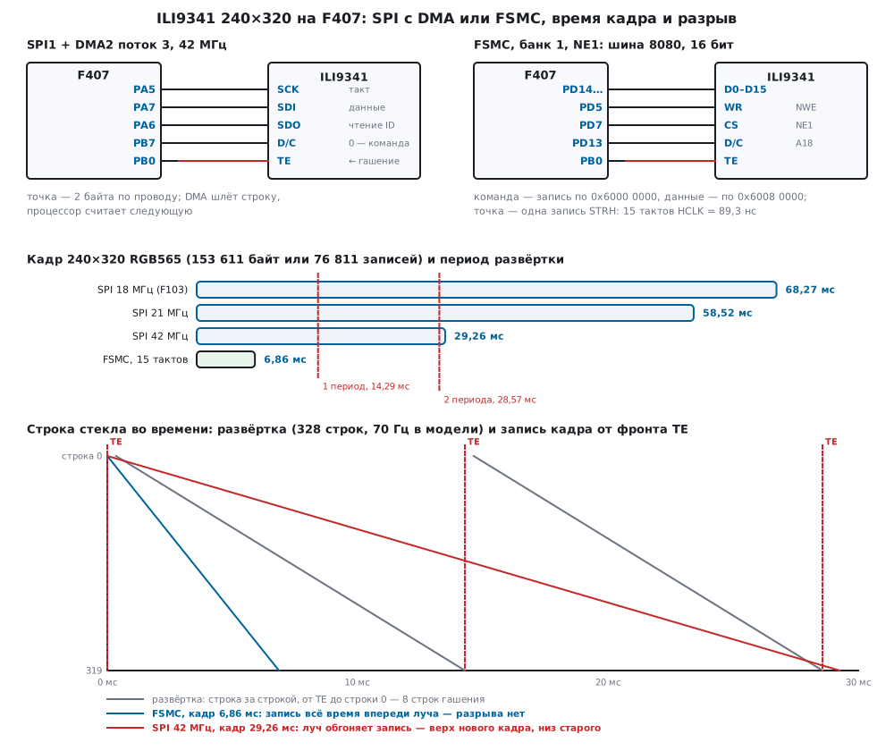
The whole screen is an 11-byte window and 76 800 points of 2 bytes: 153 611 bytes. Time is bytes × 8 / frequency, without gaps between words, as DMA sends it:
| Bus | Where | Frame | Frames per second |
|---|---|---|---|
| SPI 10 MHz | write limit per ST | 122.89 ms | 8.1 |
| SPI 18 MHz | F103: 72 / 4, F103 limit (p. 71) | 68.27 ms | 14.6 |
| SPI 21 MHz | F407: 84 / 4 | 58.52 ms | 17.1 |
| SPI 42 MHz | F407: 84 / 2, SPI1 limit (p. 35) | 29.26 ms | 34.2 |
18 MHz gives the same 68.27 ms as in 18.8; 21 MHz gives 58.52 ms versus 58.51 in 198с (no 11-byte window there). 42 MHz is allowed for SPI1 of the F407 by the datasheet, but it is four times above the 10 MHz in the ST comment: whether the module works at that frequency and on which wires is not checked.
On the F407 the pixels go through DMA2 stream 3, channel 3 (p. 308), as
16-bit words with DFF = 1 — the high byte goes first by itself. Filling
the whole screen is 76 800 equal words, and NDTR holds 65 535 (p. 331),
so there are two transfers:
static void bus_fill(uint16_t c, uint32_t n)
{
    spi_idle();
    spi_setup(1, BR_WRITE);
    DC_HIGH();
    fill_word = c;
    while (n) {                                         /* весь экран — 76 800 слов: две передачи */
        uint32_t k = n > 65535u ? 65535u : n;
        spi_idle();
        dma_go(&fill_word, k, 0);
        n -= k;
    }
}
spi_idle is the same rule as in 22з: after the DMA flag wait for TXE = 1
and BSY = 0 (p. 895) and only then touch D/C. Output through rows takes
the same 153 611 bytes, but there are now 320 DMA transfers — one per row. A
row of 240 points leaves in 91.43 µs at 42 MHz; for the core at 168 MHz that
is 15 360 cycles, 64 per point — enough to compute the next row.
22о.3 A frame does not fit into RAM: windows and dirty rectangles
A frame is 153 600 bytes. The F103C8 has 20 480 bytes of RAM (p. 1). The
F407 has 131 072 bytes in one piece for DMA — SRAM1 and SRAM2 (p. 60): also
too little. The other 65 536 bytes of CCM are invisible to DMA — only the
core can reach them (p. 68). So a double buffer is out, a single one as
well: the display keeps the picture, and the program sends only what has
changed. The buffer is two rows of 320 points, 1280 bytes: exactly the
static memory armclang reported for ili22o.o.
The example is a circle of radius 16 points moving over a gradient. The scene is a function "colour of point (x, y)"; a redraw takes the old and the new place of the circle, merges touching rectangles (the same function as in 22з) and sends them row by row:
| Step | Rectangles | Points | SPI 42 MHz, bytes | SPI 42 MHz | FSMC |
|---|---|---|---|---|---|
| whole screen | 1 | 76 800 | 153 611 | 29.26 ms | 6.858 ms |
| move by (4, 3) | old and new merged: 37 × 36 | 1332 | 2675 | 0.51 ms | 0.12 ms |
| move by (16, 12) | merged: 49 × 45 | 2205 | 4421 | 0.84 ms | 0.198 ms |
| jump | two of 33 × 33 | 2178 | 4378 | 0.83 ms | 0.196 ms |
A hundred steps (the first a jump across the screen, then 2 points each) take 243 537 bytes and 46.39 ms over SPI, on average 2435 bytes and 0.46 ms per step instead of 29.26 ms for the whole screen. After all steps the model glass matched the reference — 0 differences on both buses.
22о.4 The 8080 parallel bus through FSMC on the F407
How FSMC turns a write to an address into a cycle on the pins and why the
D/C line sits on an address line is in 41б; here is a concrete wiring. The
display is on NE1 (PD7), the WRX strobe is NWE (PD5), RDX is NOE (PD4),
the data D0–D15 are PD14, PD15, PD0, PD1, PE7–PE15, PD8, PD9, PD10, all AF12
(pp. 65–66). D/C is on line A18 (PD13). On a 16-bit bus FSMC_A[n] is
address bit n + 1 (p. 1548), hence the addresses:
#define LCD_RS_LINE 18u                                 /* FSMC_A18 */
#define LCD_CMD_ADDR 0x60000000u                        /* NE1, A18 = 0: команда */
#define LCD_DATA_ADDR (0x60000000u | 1u << (LCD_RS_LINE + 1u))   /* A18 = 1: данные, 0x60080000 */
A command is a byte written to 0x6000 0000, a parameter or a point is a word
written to 0x6008 0000: one STRH instruction, neither D/C nor waiting for
BSY. The model takes D/C from address bit 19 and builds the same picture
on both buses: 0 differences. Over SPI the test picture is 198 888 bytes,
over FSMC 99 488 writes: 99 400 points plus commands.
Timings. The STM324xG-EVAL BSP sets ADDSET 5 and DATAST 9 in mode 1 for its FSMC display at 168 MHz. A write is ADDSET + (DATAST + 1) cycles (p. 1555): 15 cycles of 5.952 ns, 89.29 ns per point. A frame is 76 811 writes and 6.858 ms, up to 145.8 frames per second. Each cycle removed from the write saves 0.457 ms per frame; how far the cycle can be shortened for the ILI9341 only its document says (how to calculate — 41б.4), and one starts with a margin.
Core or DMA. A loop of STRH in firmware cannot be faster than the bus:
FSMC has a 2-word write FIFO, and while the current cycle runs the
controller holds the next write with wait states (p. 1544) — the core stalls
for the whole frame. DMA2 in memory-to-memory mode (DMA2 only, p. 311) takes
this over:
/* «Память → память»: источник — DMA_SxPAR, приёмник — DMA_SxM0AR (RM0090, рис. 38). */
void lcd_dma_start(uint32_t dst, const uint16_t *src, uint32_t n, int src_inc)
{
    DMA2_Stream0->PAR = (uint32_t)src;
    DMA2_Stream0->M0AR = dst;                           /* адрес данных дисплея, без приращения */
    DMA2_Stream0->NDTR = n;
    DMA2_Stream0->FCR = DMA_SxFCR_DMDIS | DMA_SxFCR_FTH_0;          /* FIFO обязателен в этом режиме */
    DMA2_Stream0->CR = DMA_SxCR_DIR_1 | (src_inc ? DMA_SxCR_PINC : 0u)
                     | DMA_SxCR_PSIZE_0 | DMA_SxCR_MSIZE_0 | DMA_SxCR_PL_1 | DMA_SxCR_EN;
    dma_on = 1;
}
Here PAR is the source: a row in RAM with increment or one colour word
without it; M0AR is the display data address, without increment. Filling
the screen is the same two transfers of 65 535 and 11 265. A row of 240
points over FSMC takes 21.43 µs, only 3600 core cycles, 15 per point: the
core can no longer compute a complex scene, and with FSMC it pays to draw
rectangles and fills where there is nothing to compute.
22о.5 Comparison and tearing: TE and 0x35
| Bus | Frame | Frames per second | Core during the frame |
|---|---|---|---|
SPI 21 MHz, polling TXE |
58.52 ms plus gaps between words | below 17.1 | busy for the whole frame |
| SPI 21 MHz + DMA | 58.52 ms | 17.1 | free: 2 transfers per fill |
| SPI 42 MHz + DMA | 29.26 ms | 34.2 | free |
FSMC, STRH writes |
6.858 ms | 145.8 | stalls on every write |
| FSMC + DMA2 memory-to-memory | 6.858 ms | 145.8 | free: 2 transfers per fill |
The model does not count gaps between words when polling, nor what DMA itself adds to a cycle when accessing FSMC. FSMC is 4.3 times faster than SPI at 42 MHz.
Tearing. The ILI9341 shows its memory by itself, line by line, top to
bottom, and the program's writes know nothing about the refresh. If the
beam reaches a line before the new picture is written there, the glass
shows the top of the new frame and the bottom of the old one. Against this
the controller has the TE pin, enabled by the TEON command (0x35); per the
LVGL description the signal comes at the start of VFP — the frame blanking.
The driver sends parameter 0 — by the manufacturer's documentation that is
"blanking only", not checked. In the model the refresh is 70 frames per
second, 328 lines: 320 visible and 8 blanking lines (the line counts come
from the comment in ST's ili9341.h), a period of 14.286 ms, a line of
43.55 µs; from the TE edge to line 0 there are 8 lines. The animation is a
bar that runs across the screen in 6 frames, and the count is of refreshes
showing more than one frame:
| Case | Area write | Refreshes | Torn |
|---|---|---|---|
| FSMC, no synchronization | 6.857 ms | 5 | 3 |
| FSMC, on the TE edge | 6.857 ms | 7 | 0 |
| FSMC, on TE, rotation 180° (C8) | 6.857 ms | 7 | 6 |
FSMC, on TE, 180° and ML (D8) |
6.857 ms | 7 | 0 |
| FSMC, on TE, landscape (68) | 6.857 ms | 7 | 6 |
| SPI 42 MHz, whole screen on TE | 29.257 ms | 19 | 12 |
| SPI 42 MHz, 240 × 100 window on TE | 9.142 ms | 7 | 0 |
| SPI 42 MHz, the same window without synchronization | 9.142 ms | 6 | 1 |
The rule visible from the table: start writing at the TE edge, and the write must stay ahead of the beam all the time. FSMC writes a frame in 6.857 ms with a period of 14.286 — it keeps up. SPI at 42 MHz writes for 29.257 ms — longer than two periods (28.571 ms), and no start moment helps: only a smaller window. A window on rows 110–209 — 24 000 points in 9.142 ms — keeps up because the beam reaches row 110 later.
Two cases where TE does not help even on FSMC. With a 180° rotation the
write goes from bottom to top, against the beam; the ML bit runs the
refresh from bottom to top, and the tearing disappears — ili_rotate does
it:
void ili_rotate(ili_t *t, uint8_t rot, uint8_t ml)
{
    static const uint8_t mad[4] = {0x00u, MAD_MX | MAD_MV, MAD_MX | MAD_MY, MAD_MV | MAD_MY};
    uint8_t m = (uint8_t)((t->madctl & MAD_BGR) | mad[rot & 3u]);
    if (ml && (m & MAD_MY) && !(m & MAD_MV))
        m |= MAD_ML;                                    /* запись снизу вверх — и развёртка снизу вверх */
    t->madctl = m;
    t->w = (uint16_t)((m & MAD_MV) ? ILI_H : ILI_W);
    t->h = (uint16_t)((m & MAD_MV) ? ILI_W : ILI_H);
    t->bus->cmd(ILI_MADCTL);
    t->bus->data(&t->madctl, 1);
}
In landscape orientation (MV) the write goes along glass columns, across
the refresh, and the border between frames on the glass is a slanted line:
6 refreshes out of 7 are torn even on TE. The cure is a picture rotated in
software with portrait memory order, or small windows. The firmware waits
for the TE edge by polling the EXTI0 flag (pin PB0).
22о.6 Fonts: mono and antialiased, a string in one window, UTF-8 and Cyrillic
The font is our own: a glyph is given by polylines on a 4 × 7 grid, the
cell is 12 × 20 points. The generator gen_font22o.py splits each point of
the cell into 8 × 8 samples and counts how many lie under a stroke 1.6
points wide. Mono — a point is lit if at least half is covered;
antialiased — the coverage becomes 16 levels, 4 bits per point. A glyph is
40 bytes in mono and 120 antialiased; 51 glyphs (digits, punctuation, "°",
"C", "?" and 33 Cyrillic capitals) take 2040 and 6120 bytes plus a 102-byte
code table. armclang reported 8262 bytes of constants for font22o.o —
exactly this sum.
Antialiasing blends the text and background colours by level: for each
RGB565 component (fg · a + bg · (15 − a) + 7) / 15. Sixteen shades are
computed once per string and then taken from a table. The test string
"ТЕМПЕРАТУРА 23.5 °C" uses all 16 levels.
Cyrillic. A string in the program is UTF-8: a Cyrillic letter and "°" take two bytes, so the 19 characters of the test string are 31 bytes. The decoder extracts the code point, and the code table sorted in ascending order gives the glyph number by binary search — up to 6 comparisons for 51 glyphs:
uint32_t ili_utf8_next(const char **s)
{
    const uint8_t *p = (const uint8_t *)*s;
    uint32_t c = p[0], need, min;
    if (c == 0u)
        return 0u;
    if (c < 0x80u) {                                    /* 0xxxxxxx — ASCII */
        *s += 1;
        return c;
    }
    if ((c & 0xE0u) == 0xC0u) {                         /* 110xxxxx 10xxxxxx — кириллица, «°» */
        need = 1u, min = 0x80u, c &= 0x1Fu;
    } else if ((c & 0xF0u) == 0xE0u) {
        need = 2u, min = 0x800u, c &= 0x0Fu;
    } else if ((c & 0xF8u) == 0xF0u) {
        need = 3u, min = 0x10000u, c &= 0x07u;
    } else {                                            /* продолжение без начала или 0xF8…0xFF */
        *s += 1;
        return 0xFFFDu;
    }
    for (uint32_t i = 1; i <= need; i++) {
        if ((p[i] & 0xC0u) != 0x80u) {                 /* оборвалась: съесть только начало */
            *s += i;
            return 0xFFFDu;
        }
        c = c << 6 | (p[i] & 0x3Fu);
    }
    *s += need + 1u;
    if (c < min || c > 0x10FFFFu || (c >= 0xD800u && c <= 0xDFFFu))
        return 0xFFFDu;                                 /* лишне длинная запись, вне Юникода, суррогат */
    return c;
}
In the run Ёж gave U+0401 and U+0436: Ё is in the table, the lowercase
ж is not — "?" is drawn. A truncated D0 byte, an FF byte, the overlong
C0 AF and the surrogate ED A0 80 each gave one U+FFFD, and the "A" after FF
was not lost. "€" (three bytes) was decoded correctly but is not in the
table.
A string in one window. ili_text opens a window for the whole string
and sends 20 rows of n × 12 points, ili_text_per_glyph a window per
glyph:
| Method | SPI 42 MHz, bytes | D/C switches | DMA transfers | SPI 42 MHz | FSMC |
|---|---|---|---|---|---|
| window per string | 9131 | 6 | 20 | 1739.2 µs | 408.1 µs |
| window per glyph | 9329 | 114 | 380 | 1777.0 µs | 425.8 µs |
The byte difference is small — 18 extra windows of 11 bytes. What matters is 19 times more DMA transfers, each a stream start and a wait for the end, which the model does not count. Mono and antialiased fonts are equal in bytes: the bus carries ready RGB565 points, the difference is only in ROM. All four strings matched the model reference on both buses.
22о.7 Pitfalls
The chip code reads as FF FF FF. On many modules the SDO (MISO) pin is
not brought out or not connected. With a pull-up on PA6 the model returns
FF FF FF and the status word FF FF FF FF, ili_read_info returns 0. On the
STM32F429I-Discovery the code cannot be read for another reason: per the ST
comment the EXTC pin is not connected to the supply, and the 0xD3 command
is unavailable. A failed code check does not mean the display is broken.
Colours mixed up with byte DMA. SPI was left 8-bit and the uint16_t
array was given to DMA as bytes: in memory it lies low byte first. In the
model red became (0, 28, 198), the dark blue background almost black, 75 671
points did not match. Pixels go as words with DFF = 1 (22з); on FSMC the
bus is 16-bit anyway.
Red became blue. The glass has B-G-R order and the BGR bit is not
set: 73 110 points did not match in the model. Both open drivers, ST and
QMK, set this bit. Flip the bit, not the colours in the program.
TE was enabled but it is off. In the QMK opcode header
(qp_ili9xxx_opcodes.h) 0x34 is named "TEARING_ON" and 0x35 "TEARING_OFF";
in the ST driver and in LVGL it is the other way round: 0x35 is TEON.
Write codes, not someone else's names, and check RDDST.
Backlight. An F407 pin gives up to 25 mA (p. 79); the module backlight is not powered from a GPIO pin directly — through a transistor if the module itself has none, and the brightness is set by timer PWM. The backlight current and whether the module has a transistor depend on the module description and were not checked here.
FSMC and the board LEDs. The STM32F4-Discovery has LEDs on PD12–PD15 (BSP), and PD13 is A18, that is D/C in our wiring, PD14 and PD15 are D0 and D1. There is no remap here: in the DS8626 pin tables FSMC_A18 exists only on PD13. The way out is another address line for D/C (and recalculating the address, 41б.2) or a board without load on the bus; D0 and D1 cannot be moved. On the same board an accelerometer with select on PE3 is connected to SPI1 (PA5–PA7) — the firmware keeps PE3 high.
It tears although TE is there. A write longer than two refresh periods
(SPI at 42 MHz, the whole screen), a 180° rotation without ML or
landscape orientation — 22о.5.
22о.8 Summary
- ILI9341: 240 × 320 memory without an offset;
MADCTL— rotations 08, 68, C8, A8 and theMLrefresh order;PIXSET0x55 is 16 bits, 0x66 is 18 bits (230 411 bytes per frame); the code on0xD3is 00 93 41 after a dummy byte. - Start-up: 6 commands, 9 bytes, 240 ms of pauses.
- A frame over SPI is 153 611 bytes: 68.27 ms at 18 MHz (F103), 58.52 ms
at 21 MHz, 29.26 ms at 42 MHz (F407); a fill is 2 DMA transfers,
NDTRup to 65 535. - A 153 600-byte frame fits neither into the 20 480 bytes of the F103C8 nor into the 131 072 bytes of SRAM1 + SRAM2 of the F407; DMA does not see CCM. The buffer is two rows, 1280 bytes; a circle step averages 2435 bytes and 0.46 ms instead of 29.26 ms.
- FSMC: a command to 0x6000 0000, data to 0x6008 0000 (A18); 15 cycles — 89.29 ns per point, a frame in 6.858 ms, 145.8 frames per second; DMA — only DMA2 memory-to-memory.
- Tearing: a write from the TE edge must stay ahead of the beam. FSMC — 0 of
7 refreshes torn, SPI 42 MHz on the whole screen — 12 of 19, a 240 × 100
window — 0; 180° without
MLand landscape — 6 of 7. - A 12 × 20 font: mono 40 bytes per glyph, antialiased 120; a string in one window — 20 DMA transfers versus 380; UTF-8 → code point → binary search.
- Pitfalls: MISO and EXTC, bytes with 8-bit DMA,
BGR, the 0x34/0x35 names in QMK, the backlight, PD12–PD15 on the Discovery.
Full sources
The font tables font22o.c (683 lines) are made by the generator gen_font22o.py and lie next to the check in _verify/tft22o/.
ili22o.h — ILI9341 commands, MADCTL bits, the bus, the driver, the font, the scene: types and prototypes.
/* ili22o.h — раздел 22о: дисплей 240×320 на ILI9341 без регистров микроконтроллера.
 * Драйвер говорит с дисплеем через ili_bus_t: в прошивке это SPI1 + DMA2 (fw22o_spi.c) или
 * FSMC + DMA2 «память → память» (fw22o_fsmc.c + bus22o_fsmc.c), в стенде host22o.c — печать
 * для модели контроллера model22o.py.
 * Коды команд — как в ili9341.h драйвера ST из паков Keil (BSP Components/ili9341) и в LVGL;
 * биты MADCTL — как маски MIPI-драйвера LVGL (lv_lcd_generic_mipi.h). */
#ifndef ILI22O_H
#define ILI22O_H
#include <stdint.h>

/* ── команды ILI9341 ──────────────────────────────────────────────────── */
#define ILI_SWRESET 0x01u               /* программный сброс */
#define ILI_RDDST   0x09u               /* чтение состояния: 4 байта после холостого */
#define ILI_SLPOUT  0x11u               /* выход из сна */
#define ILI_DISPON  0x29u               /* включить показ */
#define ILI_CASET   0x2Au               /* окно: столбцы от и до */
#define ILI_PASET   0x2Bu               /* окно: строки («страницы») от и до */
#define ILI_RAMWR   0x2Cu               /* дальше — пиксели в окно */
#define ILI_TEOFF   0x34u               /* выключить вывод TE */
#define ILI_TEON    0x35u               /* включить вывод TE; параметр 0 — импульс только в гашении */
#define ILI_MADCTL  0x36u               /* порядок обхода памяти, порядок цветов, направление развёртки */
#define ILI_COLMOD  0x3Au               /* формат пикселя (PIXSET) */
#define ILI_RDID4   0xD3u               /* чтение кода микросхемы: холостой байт, 00, 93, 41 */

#define ILI_ID      0x9341u             /* как ILI9341_ID в драйвере ST */
#define COLMOD_16   0x55u               /* 16 бит на точку: RGB565, 2 байта */
#define COLMOD_18   0x66u               /* 18 бит на точку: 3 байта по SPI */

/* ── MADCTL ──────────────────────────────────────────────────────────── */
#define MAD_MY  0x80u                   /* зеркало строк */
#define MAD_MX  0x40u                   /* зеркало столбцов */
#define MAD_MV  0x20u                   /* обмен строк и столбцов: поворот на 90° */
#define MAD_ML  0x10u                   /* развёртка стекла снизу вверх (на память не влияет) */
#define MAD_BGR 0x08u                   /* стекло с порядком B-G-R */
#define MAD_MH  0x04u                   /* развёртка строки справа налево */

#define ILI_W 240u                      /* память и стекло в книжной ориентации */
#define ILI_H 320u
#define ILI_LINE_MAX 320u               /* самая длинная строка — в альбомной */
#define ILI_DIRTY_MAX 4u

/* Шина. Каждая функция сама дожидается конца предыдущей передачи и только потом трогает D/C;
 * pixels и fill могут вернуться раньше, чем всё ушло: передачу ведёт DMA. */
typedef struct {
    void (*reset)(void);
    void (*delay_ms)(uint32_t ms);
    void (*cmd)(uint8_t c);                             /* D/C = 0 */
    void (*data)(const uint8_t *p, uint32_t n);         /* D/C = 1: параметры */
    void (*pixels)(const uint16_t *px, uint32_t n);     /* D/C = 1: n точек RGB565 */
    void (*fill)(uint16_t color, uint32_t n);           /* D/C = 1: n точек одного цвета */
    void (*read)(uint8_t c, uint8_t *out, uint32_t n);  /* команда, потом n байт ответа */
    void (*wait_te)(void);                              /* дождаться фронта TE */
} ili_bus_t;

typedef struct {
    const ili_bus_t *bus;
    uint16_t w, h;                      /* после поворота */
    uint8_t madctl;
} ili_t;

typedef struct {
    uint16_t id;                        /* 0x9341, если прочитан */
    uint8_t raw[4];                     /* ответ на D3 без холостого байта… */
    uint8_t st[4];                      /* …и на RDDST: D31…D0 */
} ili_info_t;

typedef struct { int16_t x, y, w, h; } ili_rect_t;
typedef struct { ili_rect_t r[ILI_DIRTY_MAX]; uint8_t n; } ili_dirty_t;
typedef uint16_t (*ili_shader_t)(const void *ctx, int16_t x, int16_t y);

uint16_t ili_rgb(uint8_t r, uint8_t g, uint8_t b);       /* RGB888 → RGB565, как в 22з */
void ili_init(ili_t *t, const ili_bus_t *bus, uint8_t rot, uint8_t bgr);
void ili_rotate(ili_t *t, uint8_t rot, uint8_t ml);      /* 0…3; ml — развёртка по ходу записи */
int ili_read_info(const ili_t *t, ili_info_t *inf);       /* 1 — код 0x9341 прочитан */
void ili_te_on(const ili_t *t);
void ili_window(const ili_t *t, int16_t x, int16_t y, int16_t w, int16_t h);
void ili_fill_rect(const ili_t *t, int16_t x, int16_t y, int16_t w, int16_t h, uint16_t c);
void ili_shade_rect(const ili_t *t, ili_rect_t r, ili_shader_t shade, const void *ctx);

/* ── шрифт 12×20: UTF-8 → кодовая точка → номер знака ──────────────────── */
#define FONT22O_N 51
#define FONT22O_W 12
#define FONT22O_H 20
#define FONT22O_MONO_BYTES (FONT22O_H * 2)
#define FONT22O_AA_BYTES (FONT22O_W * FONT22O_H / 2)
extern const uint16_t font22o_codes[FONT22O_N];
extern const uint8_t font22o_mono[FONT22O_N][FONT22O_MONO_BYTES];
extern const uint8_t font22o_aa[FONT22O_N][FONT22O_AA_BYTES];

uint32_t ili_utf8_next(const char **s);                  /* 0 — конец строки; ошибка — U+FFFD */
int ili_glyph_index(uint32_t cp);                         /* −1 — знака нет */
uint16_t ili_blend(uint16_t fg, uint16_t bg, uint8_t a);  /* a = 0…15 */
void ili_text(const ili_t *t, int16_t x, int16_t y, const char *utf8, uint8_t aa, uint16_t fg, uint16_t bg);
void ili_text_per_glyph(const ili_t *t, int16_t x, int16_t y, const char *utf8, uint8_t aa, uint16_t fg, uint16_t bg);

/* ── «грязные» прямоугольники ─────────────────────────────────────────── */
void ili_dirty_add(ili_dirty_t *d, ili_rect_t r);
void ili_flush(const ili_t *t, ili_dirty_t *d, ili_shader_t shade, const void *ctx);

/* ── сцена примера: градиент и круг, который двигается ──────────────────── */
#define BALL_R 16
typedef struct { int16_t cx, cy; } scene_t;
uint16_t scene_shade(const void *ctx, int16_t x, int16_t y);
void scene_move(scene_t *s, ili_dirty_t *d, int16_t cx, int16_t cy);

#endif
ili22o.c — the driver: start-up, chip code, window, fill, rows, UTF-8, mono and antialiased font, dirty rectangles — shared by both firmware files and the bench.
/* ili22o.c — раздел 22о: драйвер ILI9341 (запуск, код микросхемы, окно, заливка, строки через
 * буфер, шрифт 12×20 моно и сглаженный, UTF-8, «грязные» прямоугольники) без регистров
 * микроконтроллера: общий для прошивок fw22o_spi.c, fw22o_fsmc.c и стенда host22o.c. */
#include "ili22o.h"

static uint16_t line[2][ILI_LINE_MAX];  /* две строки: DMA шлёт одну, процессор готовит другую */

uint16_t ili_rgb(uint8_t r, uint8_t g, uint8_t b)
{
    return (uint16_t)(((r & 0xF8u) << 8) | ((g & 0xFCu) << 3) | (b >> 3));
}

/* Повороты — как таблица QMK для ILI9341: 0, MX|MV, MX|MY, MV|MY. ML переворачивает развёртку
 * стекла, а не память: при 180° запись идёт снизу вверх, и развёртку пускают в ту же сторону. */
void ili_rotate(ili_t *t, uint8_t rot, uint8_t ml)
{
    static const uint8_t mad[4] = {0x00u, MAD_MX | MAD_MV, MAD_MX | MAD_MY, MAD_MV | MAD_MY};
    uint8_t m = (uint8_t)((t->madctl & MAD_BGR) | mad[rot & 3u]);
    if (ml && (m & MAD_MY) && !(m & MAD_MV))
        m |= MAD_ML;                                    /* запись снизу вверх — и развёртка снизу вверх */
    t->madctl = m;
    t->w = (uint16_t)((m & MAD_MV) ? ILI_H : ILI_W);
    t->h = (uint16_t)((m & MAD_MV) ? ILI_W : ILI_H);
    t->bus->cmd(ILI_MADCTL);
    t->bus->data(&t->madctl, 1);
}

void ili_init(ili_t *t, const ili_bus_t *bus, uint8_t rot, uint8_t bgr)
{
    static const uint8_t pixfmt = COLMOD_16;
    t->bus = bus;
    t->madctl = bgr ? MAD_BGR : 0u;
    bus->reset();
    bus->cmd(ILI_SWRESET);
    bus->delay_ms(120);                                 /* паузы с запасом: документа производителя в проекте нет */
    bus->cmd(ILI_SLPOUT);
    bus->delay_ms(120);
    bus->cmd(ILI_COLMOD);
    bus->data(&pixfmt, 1);                              /* 0x55: 16 бит и на шине MCU, и на RGB */
    ili_rotate(t, rot, 0);
    bus->cmd(ILI_DISPON);
}

int ili_read_info(const ili_t *t, ili_info_t *inf)
{
    uint8_t b[5];
    t->bus->read(ILI_RDID4, b, 4);                      /* b[0] — холостой */
    inf->raw[0] = b[1];
    inf->raw[1] = b[2];
    inf->raw[2] = b[3];
    inf->id = (uint16_t)(b[2] << 8 | b[3]);
    t->bus->read(ILI_RDDST, b, 5);
    for (int i = 0; i < 4; i++)
        inf->st[i] = b[i + 1];
    return inf->id == ILI_ID;
}

void ili_te_on(const ili_t *t)
{
    static const uint8_t vblank_only = 0x00u;           /* импульс TE только во время гашения */
    t->bus->cmd(ILI_TEON);
    t->bus->data(&vblank_only, 1);
}

void ili_window(const ili_t *t, int16_t x, int16_t y, int16_t w, int16_t h)
{
    uint16_t x1 = (uint16_t)(x + w - 1), y1 = (uint16_t)(y + h - 1);
    uint8_t ca[4] = {(uint8_t)((uint16_t)x >> 8), (uint8_t)x, (uint8_t)(x1 >> 8), (uint8_t)x1};
    uint8_t pa[4] = {(uint8_t)((uint16_t)y >> 8), (uint8_t)y, (uint8_t)(y1 >> 8), (uint8_t)y1};
    t->bus->cmd(ILI_CASET);
    t->bus->data(ca, 4);
    t->bus->cmd(ILI_PASET);
    t->bus->data(pa, 4);
    t->bus->cmd(ILI_RAMWR);
}

static int clip(const ili_t *t, ili_rect_t *r)
{
    if (r->x < 0) { r->w = (int16_t)(r->w + r->x); r->x = 0; }
    if (r->y < 0) { r->h = (int16_t)(r->h + r->y); r->y = 0; }
    if (r->x + r->w > (int16_t)t->w) r->w = (int16_t)(t->w - r->x);
    if (r->y + r->h > (int16_t)t->h) r->h = (int16_t)(t->h - r->y);
    return r->w > 0 && r->h > 0;
}

void ili_fill_rect(const ili_t *t, int16_t x, int16_t y, int16_t w, int16_t h, uint16_t c)
{
    ili_rect_t r = {x, y, w, h};
    if (!clip(t, &r))
        return;
    ili_window(t, r.x, r.y, r.w, r.h);
    t->bus->fill(c, (uint32_t)r.w * (uint32_t)r.h);     /* весь экран — 76 800 слов: больше, чем NDTR */
}

void ili_shade_rect(const ili_t *t, ili_rect_t r, ili_shader_t shade, const void *ctx)
{
    if (!clip(t, &r))
        return;
    ili_window(t, r.x, r.y, r.w, r.h);
    for (int16_t y = r.y; y < r.y + r.h; y++) {
        uint16_t *p = line[y & 1];                      /* пока DMA шлёт прошлую строку */
        for (int16_t i = 0; i < r.w; i++)
            p[i] = shade(ctx, (int16_t)(r.x + i), y);
        t->bus->pixels(p, (uint32_t)r.w);
    }
}

/* ── UTF-8 и таблица знаков ───────────────────────────────────────────── */
uint32_t ili_utf8_next(const char **s)
{
    const uint8_t *p = (const uint8_t *)*s;
    uint32_t c = p[0], need, min;
    if (c == 0u)
        return 0u;
    if (c < 0x80u) {                                    /* 0xxxxxxx — ASCII */
        *s += 1;
        return c;
    }
    if ((c & 0xE0u) == 0xC0u) {                         /* 110xxxxx 10xxxxxx — кириллица, «°» */
        need = 1u, min = 0x80u, c &= 0x1Fu;
    } else if ((c & 0xF0u) == 0xE0u) {
        need = 2u, min = 0x800u, c &= 0x0Fu;
    } else if ((c & 0xF8u) == 0xF0u) {
        need = 3u, min = 0x10000u, c &= 0x07u;
    } else {                                            /* продолжение без начала или 0xF8…0xFF */
        *s += 1;
        return 0xFFFDu;
    }
    for (uint32_t i = 1; i <= need; i++) {
        if ((p[i] & 0xC0u) != 0x80u) {                 /* оборвалась: съесть только начало */
            *s += i;
            return 0xFFFDu;
        }
        c = c << 6 | (p[i] & 0x3Fu);
    }
    *s += need + 1u;
    if (c < min || c > 0x10FFFFu || (c >= 0xD800u && c <= 0xDFFFu))
        return 0xFFFDu;                                 /* лишне длинная запись, вне Юникода, суррогат */
    return c;
}

int ili_glyph_index(uint32_t cp)
{
    int lo = 0, hi = FONT22O_N - 1;
    while (lo <= hi) {                                  /* двоичный поиск: 51 знак — до 6 сравнений */
        int mid = (lo + hi) / 2;
        if (font22o_codes[mid] == cp)
            return mid;
        if (font22o_codes[mid] < cp)
            lo = mid + 1;
        else
            hi = mid - 1;
    }
    return -1;
}

uint16_t ili_blend(uint16_t fg, uint16_t bg, uint8_t a)
{
    uint32_t r = ((fg >> 11) * a + (bg >> 11) * (15u - a) + 7u) / 15u;
    uint32_t g = (((fg >> 5) & 63u) * a + ((bg >> 5) & 63u) * (15u - a) + 7u) / 15u;
    uint32_t b = ((fg & 31u) * a + (bg & 31u) * (15u - a) + 7u) / 15u;
    return (uint16_t)(r << 11 | g << 5 | b);
}

static int glyphs(const char *s, int16_t *idx, int max)
{
    int n = 0;
    uint32_t cp;
    while (n < max && (cp = ili_utf8_next(&s)) != 0u) {
        int g = ili_glyph_index(cp);
        idx[n++] = (int16_t)(g >= 0 ? g : ili_glyph_index('?'));
    }
    return n;
}

static void glyph_row(uint16_t *p, int g, int row, uint8_t aa, const uint16_t *pal)
{
    for (int c = 0; c < FONT22O_W; c++) {
        uint8_t a;
        if (aa) {
            uint8_t b = font22o_aa[g][row * (FONT22O_W / 2) + c / 2];
            a = (uint8_t)((c & 1) ? (b & 15u) : (b >> 4));
        } else {
            a = (font22o_mono[g][row * 2 + c / 8] >> (7 - c % 8)) & 1u ? 15u : 0u;
        }
        p[c] = pal[a];
    }
}

/* Строка — одно окно на всю строку текста: 20 передач по n × 12 точек. */
void ili_text(const ili_t *t, int16_t x, int16_t y, const char *utf8, uint8_t aa, uint16_t fg, uint16_t bg)
{
    int16_t idx[ILI_LINE_MAX / FONT22O_W];
    uint16_t pal[16];
    int n = glyphs(utf8, idx, (int)(sizeof idx / sizeof idx[0]));
    if (n == 0)
        return;
    for (uint8_t a = 0; a < 16u; a++)
        pal[a] = ili_blend(fg, bg, a);                  /* 16 оттенков — один раз на строку */
    ili_window(t, x, y, (int16_t)(n * FONT22O_W), FONT22O_H);
    for (int row = 0; row < FONT22O_H; row++) {
        uint16_t *p = line[row & 1];
        for (int k = 0; k < n; k++)
            glyph_row(p + k * FONT22O_W, idx[k], row, aa, pal);
        t->bus->pixels(p, (uint32_t)(n * FONT22O_W));
    }
}

/* Для сравнения: окно на каждый знак — 20 передач по 12 точек на знак. */
void ili_text_per_glyph(const ili_t *t, int16_t x, int16_t y, const char *utf8, uint8_t aa, uint16_t fg, uint16_t bg)
{
    int16_t idx[ILI_LINE_MAX / FONT22O_W];
    uint16_t pal[16];
    int n = glyphs(utf8, idx, (int)(sizeof idx / sizeof idx[0]));
    for (uint8_t a = 0; a < 16u; a++)
        pal[a] = ili_blend(fg, bg, a);
    for (int k = 0; k < n; k++) {
        ili_window(t, (int16_t)(x + k * FONT22O_W), y, FONT22O_W, FONT22O_H);
        for (int row = 0; row < FONT22O_H; row++) {
            uint16_t *p = line[row & 1];
            glyph_row(p, idx[k], row, aa, pal);
            t->bus->pixels(p, FONT22O_W);
        }
    }
}

/* ── «грязные» прямоугольники ─────────────────────────────────────────── */
static int touch(ili_rect_t a, ili_rect_t b)
{
    return a.x <= b.x + b.w && b.x <= a.x + a.w && a.y <= b.y + b.h && b.y <= a.y + a.h;
}

static ili_rect_t bbox(ili_rect_t a, ili_rect_t b)
{
    int16_t x0 = a.x < b.x ? a.x : b.x, y0 = a.y < b.y ? a.y : b.y;
    int16_t x1 = a.x + a.w > b.x + b.w ? (int16_t)(a.x + a.w) : (int16_t)(b.x + b.w);
    int16_t y1 = a.y + a.h > b.y + b.h ? (int16_t)(a.y + a.h) : (int16_t)(b.y + b.h);
    return (ili_rect_t){x0, y0, (int16_t)(x1 - x0), (int16_t)(y1 - y0)};
}

void ili_dirty_add(ili_dirty_t *d, ili_rect_t r)
{
    if (r.w <= 0 || r.h <= 0)
        return;
    for (uint8_t i = 0; i < d->n; i++)
        if (touch(d->r[i], r)) {                        /* касается — объединить */
            r = bbox(d->r[i], r);
            d->r[i] = d->r[--d->n];
            ili_dirty_add(d, r);
            return;
        }
    if (d->n < ILI_DIRTY_MAX)
        d->r[d->n++] = r;
    else
        ili_dirty_add(d, bbox(d->r[--d->n], r));
}

void ili_flush(const ili_t *t, ili_dirty_t *d, ili_shader_t shade, const void *ctx)
{
    for (uint8_t k = 0; k < d->n; k++)
        ili_shade_rect(t, d->r[k], shade, ctx);
    d->n = 0;
}

/* ── сцена: вертикальный градиент и круг ──────────────────────────────── */
uint16_t scene_shade(const void *ctx, int16_t x, int16_t y)
{
    const scene_t *s = ctx;
    int dx = x - s->cx, dy = y - s->cy;
    if (dx * dx + dy * dy <= BALL_R * BALL_R)
        return ili_rgb(255, 128, 0);
    return ili_rgb(0, (uint8_t)(y * 255 / 319), (uint8_t)(255 - y * 255 / 319));
}

void scene_move(scene_t *s, ili_dirty_t *d, int16_t cx, int16_t cy)
{
    ili_dirty_add(d, (ili_rect_t){(int16_t)(s->cx - BALL_R), (int16_t)(s->cy - BALL_R), 2 * BALL_R + 1, 2 * BALL_R + 1});
    s->cx = cx;
    s->cy = cy;
    ili_dirty_add(d, (ili_rect_t){(int16_t)(cx - BALL_R), (int16_t)(cy - BALL_R), 2 * BALL_R + 1, 2 * BALL_R + 1});
}
bus22o_fsmc.c — the ili_bus_t bus over FSMC: command and data addresses, STRH writes, memory-to-memory DMA.
/* bus22o_fsmc.c — раздел 22о: шина ili_bus_t поверх FSMC (8080, 16 бит) на STM32F407.
 * Дисплей на NE1, вход D/C (RS) — на линии FSMC_A18 (PD13). На 16-битной шине FSMC_A[n] = HADDR[n+1]
 * (RM0090, таблица 217; раздел 41б.2), поэтому данные — по 0x6008 0000, а не по 0x6004 0000.
 * Запись — одна инструкция STRH; пиксели — DMA2 «память → память»: источник — строка в ОЗУ
 * или одно слово цвета, приёмник — адрес данных без приращения.
 * Железо (сброс, паузы, TE, DMA) — в fw22o_fsmc.c; в стенде host22o.c — печать для модели,
 * а запись и чтение по адресу подменяются (-DFSMC_HOST). */
#include "ili22o.h"

#ifdef FSMC_HOST
void host_wr(uint32_t a, uint16_t v);
uint16_t host_rd(uint32_t a);
#define FSMC_WR(a, v) host_wr((a), (uint16_t)(v))
#define FSMC_RD(a) host_rd(a)
#else
#define FSMC_WR(a, v) (*(volatile uint16_t *)(a) = (uint16_t)(v))   /* одна инструкция STRH */
#define FSMC_RD(a) (*(volatile uint16_t *)(a))
#endif

#define LCD_RS_LINE 18u                                 /* FSMC_A18 */
#define LCD_CMD_ADDR 0x60000000u                        /* NE1, A18 = 0: команда */
#define LCD_DATA_ADDR (0x60000000u | 1u << (LCD_RS_LINE + 1u))   /* A18 = 1: данные, 0x60080000 */

void lcd_hw_reset(void);
void lcd_hw_delay_ms(uint32_t ms);
void lcd_hw_wait_te(void);
void lcd_dma_start(uint32_t dst, const uint16_t *src, uint32_t n, int src_inc);
void lcd_dma_wait(void);

static uint16_t fill_word;                              /* цвет заливки: DMA читает его без приращения */

static void f_cmd(uint8_t c)
{
    lcd_dma_wait();                                     /* пиксели прошлой передачи ушли */
    FSMC_WR(LCD_CMD_ADDR, c);
}

static void f_data(const uint8_t *p, uint32_t n)
{
    lcd_dma_wait();
    while (n--)
        FSMC_WR(LCD_DATA_ADDR, *p++);                   /* параметр — младшие 8 бит слова */
}

static void f_pixels_dma(const uint16_t *px, uint32_t n)
{
    lcd_dma_wait();
    lcd_dma_start(LCD_DATA_ADDR, px, n, 1);             /* и сразу назад: строку пишет DMA */
}

static void f_fill_dma(uint16_t c, uint32_t n)
{
    lcd_dma_wait();
    fill_word = c;
    while (n) {
        uint32_t k = n > 65535u ? 65535u : n;           /* NDTR — до 65 535 (RM0090, с. 331) */
        lcd_dma_wait();
        lcd_dma_start(LCD_DATA_ADDR, &fill_word, k, 0);
        n -= k;
    }
}

static void f_pixels_cpu(const uint16_t *px, uint32_t n)
{
    while (n--)
        FSMC_WR(LCD_DATA_ADDR, *px++);                  /* процессор стоит, пока идёт цикл шины */
}

static void f_fill_cpu(uint16_t c, uint32_t n)
{
    while (n--)
        FSMC_WR(LCD_DATA_ADDR, c);
}

static void f_read(uint8_t c, uint8_t *out, uint32_t n)
{
    lcd_dma_wait();
    FSMC_WR(LCD_CMD_ADDR, c);
    for (uint32_t i = 0; i < n; i++)
        out[i] = (uint8_t)FSMC_RD(LCD_DATA_ADDR);       /* первое чтение — холостое */
}

const ili_bus_t fsmc_bus_dma = {lcd_hw_reset, lcd_hw_delay_ms, f_cmd, f_data, f_pixels_dma, f_fill_dma, f_read, lcd_hw_wait_te};
const ili_bus_t fsmc_bus_cpu = {lcd_hw_reset, lcd_hw_delay_ms, f_cmd, f_data, f_pixels_cpu, f_fill_cpu, f_read, lcd_hw_wait_te};
fw22o_spi.c — STM32F407 firmware: SPI1 and DMA2 stream 3, code reading, TE on EXTI0, the circle on TE.
/* fw22o_spi.c — раздел 22о: ILI9341 на STM32F407 по SPI1 с DMA, 168 МГц, APB2 84 МГц.
 * SCK — PA5, MISO — PA6 (с подтяжкой вверх), MOSI — PA7 (AF5); CS — PB6, D/C — PB7, RST — PB8,
 * TE — PB0 (EXTI0), подсветка — PB1. На STM32F4DISCOVERY к тем же PA5–PA7 подключён акселерометр
 * с выбором на PE3 — его держим в единице.
 * Запись — 84 / 2 = 42 МГц, чтение — 84 / 16 = 5,25 МГц (ST в файле платы 429I-Discovery пишет для
 * ILI9341 о 10 МГц на запись и 6,66 МГц на чтение). Пиксели — DMA2 поток 3 канал 3 (SPI1_TX,
 * RM0090, с. 308) словами по 16 бит: старший байт первым сам. Тактирование — как в разделе 6. */
#include "stm32f4xx.h"
#include "ili22o.h"

#define BR_WRITE 0u                                     /* /2: 42 МГц; SPI_CR1_BR_0 — /4: 21 МГц */
#define BR_READ (SPI_CR1_BR_1 | SPI_CR1_BR_0)           /* /16: 5,25 МГц */
#define CS_LOW()  (GPIOB->BSRR = 1u << (6 + 16))
#define DC_LOW()  (GPIOB->BSRR = 1u << (7 + 16))
#define DC_HIGH() (GPIOB->BSRR = 1u << 7)

static volatile uint32_t ticks;
static uint8_t dma_on;
static uint16_t fill_word;

void SysTick_Handler(void)
{
    ticks++;
}

static void delay_ms(uint32_t ms)
{
    uint32_t t0 = ticks;
    while (ticks - t0 < ms) {
    }
}

/* Конец передачи: DMA отдал последнее слово, потом TXE = 1 и BSY = 0 (RM0090, с. 895). */
static void spi_idle(void)
{
    if (dma_on) {
        while (!(DMA2->LISR & DMA_LISR_TCIF3)) {
        }
        DMA2->LIFCR = DMA_LIFCR_CTCIF3 | DMA_LIFCR_CHTIF3 | DMA_LIFCR_CTEIF3 | DMA_LIFCR_CDMEIF3 | DMA_LIFCR_CFEIF3;
        dma_on = 0;
    }
    while (!(SPI1->SR & SPI_SR_TXE)) {
    }
    while (SPI1->SR & SPI_SR_BSY) {
    }
    (void)SPI1->DR;                                     /* приём не читали: снять RXNE и OVR */
    (void)SPI1->SR;
}

static void spi_setup(uint8_t w16, uint32_t br)        /* DFF и BR — только при выключенном SPI */
{
    uint32_t cr = (SPI1->CR1 & ~(SPI_CR1_DFF | SPI_CR1_BR)) | (w16 ? SPI_CR1_DFF : 0u) | br;
    if (cr == SPI1->CR1)
        return;
    SPI1->CR1 &= ~SPI_CR1_SPE;
    SPI1->CR1 = cr & ~SPI_CR1_SPE;
    SPI1->CR1 = cr | SPI_CR1_SPE;
}

static void dma_go(const void *src, uint32_t n, uint32_t minc)
{
    DMA2_Stream3->M0AR = (uint32_t)src;
    DMA2_Stream3->NDTR = n;                             /* до 65 535 (RM0090, с. 331) */
    DMA2_Stream3->CR = 3u << DMA_SxCR_CHSEL_Pos | DMA_SxCR_DIR_0 | minc
                     | DMA_SxCR_PSIZE_0 | DMA_SxCR_MSIZE_0 | DMA_SxCR_EN;
    dma_on = 1;
}

static void bus_reset(void)
{
    GPIOB->BSRR = 1u << (8 + 16);
    delay_ms(10);
    GPIOB->BSRR = 1u << 8;
    delay_ms(10);
}

static void bus_cmd(uint8_t c)
{
    spi_idle();
    spi_setup(0, BR_WRITE);
    DC_LOW();
    SPI1->DR = c;
}

static void bus_data(const uint8_t *p, uint32_t n)
{
    spi_idle();
    spi_setup(0, BR_WRITE);
    DC_HIGH();
    while (n--) {
        while (!(SPI1->SR & SPI_SR_TXE)) {
        }
        SPI1->DR = *p++;
    }
}

static void bus_pixels(const uint16_t *px, uint32_t n)
{
    spi_idle();
    spi_setup(1, BR_WRITE);
    DC_HIGH();
    dma_go(px, n, DMA_SxCR_MINC);
}

static void bus_fill(uint16_t c, uint32_t n)
{
    spi_idle();
    spi_setup(1, BR_WRITE);
    DC_HIGH();
    fill_word = c;
    while (n) {                                         /* весь экран — 76 800 слов: две передачи */
        uint32_t k = n > 65535u ? 65535u : n;
        spi_idle();
        dma_go(&fill_word, k, 0);
        n -= k;
    }
}

static void bus_read(uint8_t c, uint8_t *out, uint32_t n)
{
    bus_cmd(c);
    spi_idle();
    spi_setup(0, BR_READ);                              /* чтение медленнее записи */
    DC_HIGH();
    for (uint32_t i = 0; i < n; i++) {
        SPI1->DR = 0x00u;                               /* такт для ответа */
        while (!(SPI1->SR & SPI_SR_RXNE)) {
        }
        out[i] = (uint8_t)SPI1->DR;
    }
    spi_idle();
    spi_setup(0, BR_WRITE);
}

static void bus_wait_te(void)
{
    EXTI->PR = EXTI_PR_PR0;
    while (!(EXTI->PR & EXTI_PR_PR0)) {
    }
}

static const ili_bus_t bus = {bus_reset, delay_ms, bus_cmd, bus_data, bus_pixels, bus_fill, bus_read, bus_wait_te};
static ili_t lcd;
static ili_info_t info;
static ili_dirty_t dirty;
static scene_t ball = {120, 160};

int main(void)
{
    RCC->AHB1ENR |= RCC_AHB1ENR_GPIOAEN | RCC_AHB1ENR_GPIOBEN | RCC_AHB1ENR_GPIOEEN | RCC_AHB1ENR_DMA2EN;
    RCC->APB2ENR |= RCC_APB2ENR_SPI1EN | RCC_APB2ENR_SYSCFGEN;
    GPIOE->BSRR = 1u << 3;                              /* акселерометр Discovery: CS в 1 */
    GPIOE->MODER = (GPIOE->MODER & ~(3u << 6)) | 1u << 6;
    GPIOA->MODER = (GPIOA->MODER & ~(0x3Fu << 10)) | 0x2Au << 10;  /* PA5–PA7 — AF */
    GPIOA->AFR[0] = (GPIOA->AFR[0] & ~(0xFFFu << 20)) | 0x555u << 20;
    GPIOA->OSPEEDR |= 0x3Fu << 10;
    GPIOA->PUPDR = (GPIOA->PUPDR & ~(3u << 12)) | 1u << 12;        /* MISO с подтяжкой: без провода — 0xFF */
    GPIOB->BSRR = 1u << 7 | 1u << 8 | 1u << (6 + 16);
    GPIOB->MODER = (GPIOB->MODER & ~(3u << 0 | 3u << 2 | 0x3Fu << 12)) | 1u << 2 | 0x15u << 12;
    SYSCFG->EXTICR[0] = (SYSCFG->EXTICR[0] & ~SYSCFG_EXTICR1_EXTI0) | SYSCFG_EXTICR1_EXTI0_PB;
    EXTI->RTSR |= EXTI_RTSR_TR0;
    EXTI->IMR |= EXTI_IMR_MR0;
    SPI1->CR1 = SPI_CR1_MSTR | SPI_CR1_SSM | SPI_CR1_SSI | BR_WRITE;   /* режим 0, как у ST для ILI9341 */
    SPI1->CR2 = SPI_CR2_TXDMAEN;
    SPI1->CR1 |= SPI_CR1_SPE;
    DMA2_Stream3->PAR = (uint32_t)&SPI1->DR;
    SysTick_Config(168000u);

    ili_init(&lcd, &bus, 0, 1);
    if (!ili_read_info(&lcd, &info)) {                  /* без MISO или без EXTC — 0xFF… */
        GPIOB->BSRR = 1u << 1;
        ili_fill_rect(&lcd, 0, 0, (int16_t)lcd.w, (int16_t)lcd.h, ili_rgb(255, 0, 0));
        for (;;) {
        }
    }
    ili_te_on(&lcd);
    GPIOB->BSRR = 1u << 1;
    ili_dirty_add(&dirty, (ili_rect_t){0, 0, (int16_t)lcd.w, (int16_t)lcd.h});
    ili_flush(&lcd, &dirty, scene_shade, &ball);
    int16_t dx = 2, dy = 3;
    for (;;) {                                          /* маленькое окно успевает до развёртки */
        if (ball.cx + dx < BALL_R || ball.cx + dx > (int16_t)lcd.w - 1 - BALL_R)
            dx = (int16_t)-dx;
        if (ball.cy + dy < BALL_R || ball.cy + dy > (int16_t)lcd.h - 1 - BALL_R)
            dy = (int16_t)-dy;
        scene_move(&ball, &dirty, (int16_t)(ball.cx + dx), (int16_t)(ball.cy + dy));
        bus.wait_te();
        ili_flush(&lcd, &dirty, scene_shade, &ball);
    }
}
fw22o_fsmc.c — STM32F407 firmware: FSMC pins, timings, DMA2 stream 0, the circle on TE.
/* fw22o_fsmc.c — раздел 22о: ILI9341 на STM32F407 по шине 8080 через FSMC, 168 МГц.
 * NE1 — PD7, NOE — PD4, NWE — PD5, D/C (RS) — FSMC_A18 = PD13; D0–D15: PD14, PD15, PD0, PD1, PE7–PE15,
 * PD8, PD9, PD10 — всё AF12 (DS8626, таблица 9). RST — PB8, TE — PB0 (EXTI0), подсветка — PB1.
 * Тайминги — как у BSP STM324xG-EVAL для его дисплея на FSMC: ADDSET 5, DATAST 9, режим 1:
 * запись 5 + 9 + 1 = 15 тактов HCLK = 89,3 нс. Пиксели — DMA2 поток 0 «память → память»
 * (только DMA2 так умеет, RM0090, с. 311). Шина ili_bus_t — bus22o_fsmc.c.
 * Тактирование до 168 МГц — как в разделе 6 (здесь не повторяется). */
#include "stm32f4xx.h"
#include "ili22o.h"

extern const ili_bus_t fsmc_bus_dma;

#define BTR(addset, datast, busturn) \
    (((uint32_t)(addset) << FSMC_BTR1_ADDSET_Pos) | ((uint32_t)(datast) << FSMC_BTR1_DATAST_Pos) | \
     ((uint32_t)(busturn) << FSMC_BTR1_BUSTURN_Pos))

static volatile uint32_t ticks;
static uint8_t dma_on;

void SysTick_Handler(void)
{
    ticks++;
}

void lcd_hw_delay_ms(uint32_t ms)
{
    uint32_t t0 = ticks;
    while (ticks - t0 < ms) {
    }
}

void lcd_hw_reset(void)
{
    GPIOB->BSRR = 1u << (8 + 16);
    lcd_hw_delay_ms(10);
    GPIOB->BSRR = 1u << 8;
    lcd_hw_delay_ms(10);
}

void lcd_hw_wait_te(void)               /* фронт TE ставит флаг EXTI0; прерывание в NVIC не включено */
{
    EXTI->PR = EXTI_PR_PR0;
    while (!(EXTI->PR & EXTI_PR_PR0)) {
    }
}

void lcd_dma_wait(void)
{
    if (!dma_on)
        return;
    while (!(DMA2->LISR & DMA_LISR_TCIF0)) {
    }
    DMA2->LIFCR = DMA_LIFCR_CTCIF0 | DMA_LIFCR_CHTIF0 | DMA_LIFCR_CTEIF0 | DMA_LIFCR_CDMEIF0 | DMA_LIFCR_CFEIF0;
    dma_on = 0;
}

/* «Память → память»: источник — DMA_SxPAR, приёмник — DMA_SxM0AR (RM0090, рис. 38). */
void lcd_dma_start(uint32_t dst, const uint16_t *src, uint32_t n, int src_inc)
{
    DMA2_Stream0->PAR = (uint32_t)src;
    DMA2_Stream0->M0AR = dst;                           /* адрес данных дисплея, без приращения */
    DMA2_Stream0->NDTR = n;
    DMA2_Stream0->FCR = DMA_SxFCR_DMDIS | DMA_SxFCR_FTH_0;          /* FIFO обязателен в этом режиме */
    DMA2_Stream0->CR = DMA_SxCR_DIR_1 | (src_inc ? DMA_SxCR_PINC : 0u)
                     | DMA_SxCR_PSIZE_0 | DMA_SxCR_MSIZE_0 | DMA_SxCR_PL_1 | DMA_SxCR_EN;
    dma_on = 1;
}

static void gpio_af12(GPIO_TypeDef *g, uint32_t pins)
{
    for (uint32_t p = 0; p < 16u; p++) {
        if (!(pins >> p & 1u))
            continue;
        g->MODER = (g->MODER & ~(3u << 2 * p)) | 2u << 2 * p;
        g->OSPEEDR |= 3u << 2 * p;
        g->AFR[p >> 3] = (g->AFR[p >> 3] & ~(15u << 4 * (p & 7u))) | 12u << 4 * (p & 7u);
    }
}

static void fsmc_lcd_init(void)
{
    RCC->AHB3ENR |= RCC_AHB3ENR_FSMCEN;
    FSMC_Bank1->BTCR[1] = BTR(5, 9, 0);                 /* BTR1: как BSP STM324xG-EVAL */
    FSMC_Bank1->BTCR[0] = (FSMC_Bank1->BTCR[0]          /* после сброса — NOR с MUXEN, его снять */
                           & ~(FSMC_BCR1_MUXEN | FSMC_BCR1_MTYP | FSMC_BCR1_MWID | FSMC_BCR1_WAITEN | FSMC_BCR1_EXTMOD))
                        | FSMC_BCR1_MWID_0 | FSMC_BCR1_WREN | FSMC_BCR1_MBKEN;
}

static ili_t lcd;
static ili_dirty_t dirty;
static scene_t ball = {120, 160};

int main(void)
{
    RCC->AHB1ENR |= RCC_AHB1ENR_GPIOBEN | RCC_AHB1ENR_GPIODEN | RCC_AHB1ENR_GPIOEEN | RCC_AHB1ENR_DMA2EN;
    RCC->APB2ENR |= RCC_APB2ENR_SYSCFGEN;
    gpio_af12(GPIOD, 1u << 0 | 1u << 1 | 1u << 4 | 1u << 5 | 1u << 7 | 1u << 8 | 1u << 9 | 1u << 10
                         | 1u << 13 | 1u << 14 | 1u << 15);
    gpio_af12(GPIOE, 0xFF80u);                          /* PE7–PE15 */
    GPIOB->BSRR = 1u << 8;                              /* RST в 1 */
    GPIOB->MODER = (GPIOB->MODER & ~(3u << 0 | 3u << 2 | 3u << 16)) | 1u << 2 | 1u << 16;   /* PB1, PB8 — выходы, PB0 — вход */
    SYSCFG->EXTICR[0] = (SYSCFG->EXTICR[0] & ~SYSCFG_EXTICR1_EXTI0) | SYSCFG_EXTICR1_EXTI0_PB;
    EXTI->RTSR |= EXTI_RTSR_TR0;
    EXTI->IMR |= EXTI_IMR_MR0;
    fsmc_lcd_init();
    SysTick_Config(168000u);                            /* 1 мс */

    ili_init(&lcd, &fsmc_bus_dma, 0, 1);
    ili_te_on(&lcd);
    GPIOB->BSRR = 1u << 1;                              /* подсветка */
    ili_dirty_add(&dirty, (ili_rect_t){0, 0, (int16_t)lcd.w, (int16_t)lcd.h});
    ili_flush(&lcd, &dirty, scene_shade, &ball);
    ili_text(&lcd, 4, 8, "ТЕМПЕРАТУРА 23,5 °C", 1, ili_rgb(255, 255, 255), ili_rgb(0, 0, 64));
    int16_t dx = 2, dy = 3;
    for (;;) {                                          /* круг отскакивает от краёв, кадр — по TE */
        int16_t x = (int16_t)(ball.cx + dx), y = (int16_t)(ball.cy + dy);
        if (x < BALL_R || x > (int16_t)lcd.w - 1 - BALL_R)
            dx = (int16_t)-dx;
        if (y < 40 + BALL_R || y > (int16_t)lcd.h - 1 - BALL_R)
            dy = (int16_t)-dy;
        scene_move(&ball, &dirty, (int16_t)(ball.cx + dx), (int16_t)(ball.cy + dy));
        fsmc_bus_dma.wait_te();
        ili_flush(&lcd, &dirty, scene_shade, &ball);
    }
}
Next: section 43 "Hardware cryptography: CRC, RNG, HASH, CRYP".