 Embedded HandbookApps
175. Comparators: delay, open-drain output, hysteresis, window comparator
An op-amp with hysteresis already appeared in 56.7, and the built-in comparators of the STM32 in section 44. This section is about the device itself: why the delay depends on how far the signal has crossed the threshold, what is different about an open-drain output, how to calculate hysteresis and how two comparators make a "voltage within tolerance" monitor.
The numbers below come from an ngspice model of a comparator with explicitly set parameters (gain 100000, bandwidth 1 MHz, limited current of the internal node) and a small-signal switch at the output.
Terms used in the documentation
Term Meaning propagation delay (tPD) the time from the input crossing to the output switching input overdrive how far the input goes beyond the threshold open-drain / open-collector output an output that can only pull the line low push-pull output an output that drives both high and low pull-up resistor the resistor that pulls the line up to the supply hysteresis different thresholds for rising and falling inputs Schmitt trigger an input or comparator with hysteresis window comparator two comparators that check a voltage is within limits wired-OR several outputs sharing one line response time the switching time of a comparator
175.1 A comparator is not an op-amp
In circuit terms it is the same differential amplifier, but the jobs differ: an amplifier must be stable with feedback and is therefore deliberately slowed down (section 163), while a comparator is not used with feedback — it is not compensated inside, and it is tens of times faster.
This leads to three differences you can see on the board:
- the output of a comparator is digital: either push-pull or open-drain; saturation is its normal operating mode, not a fault;
- there is no feedback, so there is no bandwidth either: there is only delay;
- an op-amp used as a comparator works, but badly: it comes out of saturation slowly (microseconds), and its input may have protection not designed for a large differential voltage.
The STM32 has comparators inside (section 44.6), and they have the same properties: delay, hysteresis, choice of reference.
175.2 Delay depends on input overdrive
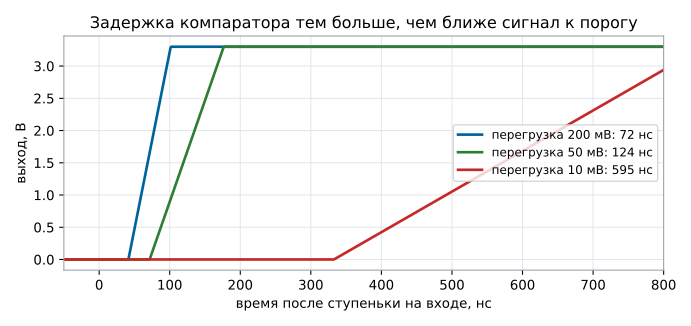
Threshold 1.65 V; the input gets a step that crosses it by 10, 50 and 200 mV:
| Input overdrive | Delay until the output switches |
|---|---|
| 10 mV | 595 ns |
| 50 mV | 124 ns |
| 200 mV | 71 ns |
The reason is simple: the slew rate of the internal node is set by a current that is proportional to the difference at the inputs. The closer the signal is to the threshold, the slower the switching — at 10 mV the delay is 8.3 times longer than at 200 mV. That is why the documentation always gives the response time at a specified overdrive, usually 5, 10 or 100 mV, and comparing parts specified at different overdrives is meaningless.
The practical conclusion: if the signal approaches the threshold slowly (a sensor, an integrator, slow charging), the comparator will switch not "at the point" but later — and the slower the signal, the later.
175.3 Open-drain output
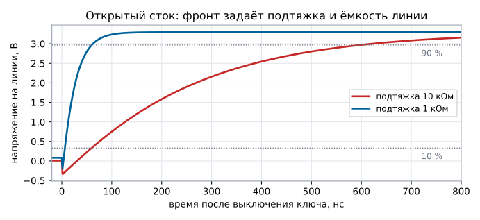
An open drain is an internal switch that pulls the line to ground; an external resistor pulls it up. The price of this flexibility is speed: the edge is set by the RC of the pull-up and the line capacitance. The model with 20 pF:
| Pull-up | Edge (10…90 %) | Low level | Current in the low state |
|---|---|---|---|
| 10 kΩ | 538 ns | 8.3 mV | 0.33 mA |
| 1 kΩ | 54 ns | 81.4 mV | 3.22 mA |
The edge is proportional to the pull-up resistance: 2.2 · R · C gives the same
538 ns at 24.5 pF (20 pF of the line plus about 4.5 pF of the switch itself). The low
level is the current through the on-resistance of the switch, 25 Ω here.
The price of a fast pull-up: in the low state current flows through it constantly — 1.1 mW at 10 kΩ and 10.6 mW at 1 kΩ. For a battery device that is a lot, for a mains-powered board it is nothing.
On the other hand, an open drain can do what a push-pull output cannot:
- wired-OR: several outputs on one line, any of them pulls it low — this is how a window comparator and an "alarm" signal from several sources are made;
- a different level: a pull-up to 5 V turns the output into a five-volt one — if the output allows it: look up the maximum voltage on it in the documentation, on many parts it is no higher than the supply, and on the STM32 only FT pins tolerate 5 V; a pull-up to 1.8 V gives a 1.8 V output, while the comparator itself runs from 3.3 V.
175.4 Chatter and hysteresis
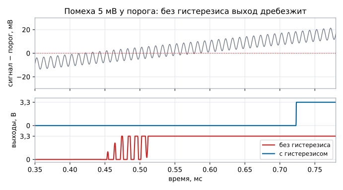
If the signal approaches the threshold slowly, any noise flips the output back and forth. The model: the signal goes from 1.62 to 1.68 V in a millisecond, with 5 mV of noise at 100 kHz on it.
| Circuit | Output transitions |
|---|---|
| without hysteresis | 11 |
| with 32.7 mV hysteresis | 1 |
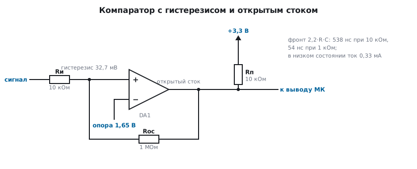
Hysteresis is made with positive feedback: part of the output
voltage is fed back to the same input. The signal is applied to "+" through
Rin = 10 kΩ, and Rfb = 1 MΩ goes from the output to the same input; the hysteresis width
referred to the input is Uout · Rin / Rfb. With an open-drain output the high level
arrives through the pull-up, and its 10 kΩ adds to Rfb:
Uout · Rin / (Rfb + Rpu) = 3.3 · 10 kΩ / 1.01 MΩ = 32.7 mV — more than
the noise amplitude, and the chatter disappears. (The formula Uout · Rin / (Rin + Rfb) is for
a different circuit: the reference on "+" through Rin, the signal on "−".)
The rule of choice: make the hysteresis larger than the amplitude of the interference and noise at the input (section 165), but smaller than the allowed threshold error. If the interference is poorly known, start with 20…50 mV.
175.5 Window comparator
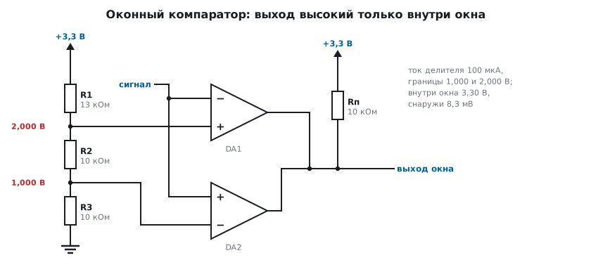
The "voltage within tolerance" task is solved with two comparators: one watches the upper limit, the other the lower one, and the outputs share one line with a common pull-up. The thresholds come from a divider of three resistors: 13 kΩ, 10 kΩ and 10 kΩ from 3.3 V — a current of 100 µA, limits of 1.000 and 2.000 V.
| Input voltage | Output |
|---|---|
| 0.5 V — below the window | 8.3 mV |
| 1.5 V — inside the window | 3.30 V |
| 2.5 V — above the window | 8.3 mV |
Connection: on the upper comparator the signal goes to the inverting input, and the 2.0 V threshold to the non-inverting one; on the lower one it is the other way round — the signal to the non-inverting input, the 1.0 V threshold to the inverting one. An open-drain output is released when "+" is higher than "−", so the line stays high only while both are released.
The trip points in the model are 1.001 and 1.999 V: exactly the divider thresholds. Such a block is used when the microcontroller should not have to poll the ADC: the output is connected to an interrupt pin, and it reports by itself that the voltage has gone out of tolerance.
Hysteresis is needed here too — otherwise at the edge of the window the output will chatter exactly as in 175.4.
175.6 Pitfalls
The comparator is "slow", although the documentation says 40 ns. The time is given at an overdrive of 100 mV; at 10 mV it is several times slower — in the model 595 versus 71 ns.
The output does not rise to the supply. An open drain without a pull-up; the resistor is mandatory, and it also sets the edge.
The edge is stretched to microseconds. A 100 kΩ pull-up on a line with capacitance:
2.2 · R · C.
The output chatters on a slow signal. No hysteresis: in the model 11 transitions instead of one.
There is hysteresis, but the chatter remains. The width is smaller than the noise amplitude;
calculate it with Uout · Rin / (Rfb + Rpu).
An op-amp used instead of a comparator "sometimes lags". Coming out of saturation takes microseconds, and this depends on the input overdrive even more strongly.
175.7 Summary
- Comparator delay depends on the input overdrive: 595 ns at 10 mV, 124 ns at 50 mV and 71 ns at 200 mV — a factor of 8.3.
- Open drain: edge
2.2 · R · C— 538 ns at 10 kΩ and 54 ns at 1 kΩ; low level 8.3 and 81.4 mV across a switch resistance of 25 Ω. - Pull-up current in the low state is 0.33 and 3.22 mA, that is 1.1 and 10.6 mW.
- Hysteresis
Uout · Rin / (Rfb + Rpu)= 32.7 mV removes the chatter: 1 transition instead of 11. - A window comparator on a 13 / 10 / 10 kΩ divider gives limits of 1.000 and 2.000 V, and the output is high only inside the window.
Next: section 176 "Instrumentation amplifier".