 Embedded HandbookApps
60. Multiplexers, decoders, combinational circuits
Gates (section 59) are combined into larger building blocks. There are only a few of them, and they turn up everywhere — inside the microcontroller and on the board next to it. Once you know them, you start to see them in descriptions: "pin alternate function multiplexer", "address decoder", "interrupt priority encoder" — these are all the same blocks.
This section covers four such blocks and two practical tasks they solve: expanding the number of outputs and connecting several sensors to one ADC input.
Terms used in the documentation
Term Meaning combinational logic a logic circuit without memory multiplexer (mux) a selector, a "switch" between inputs demultiplexer, decoder routes to, or activates, one of several outputs encoder, priority encoder turns active inputs into a number; the highest wins enable an input that allows the block to work half / full adder adds two bits / three bits carry, ripple carry the carry bit; carry passed stage by stage carry-lookahead carry computed by a separate fast circuit shift register a register that moves bits in one at a time analog switch, on-resistance a switch for analog signals; resistance of the closed switch latch a stage that holds the value on its outputs
60.1 Combinational means no memory
The output of a combinational circuit depends only on what is on its inputs right now. Apply the same input set and you get the same result, regardless of history. Everything in this section is like that.
The opposite is circuits with memory (flip-flops, registers, counters), where the result also depends on the previous state. Peripheral registers are built from them, and they are covered in the sections about the microcontroller itself.
60.2 Multiplexer: one of many
It passes one of several inputs to the output — the one whose number is given by the address.
| Address lines | Inputs |
|---|---|
| 1 | 2 |
| 2 | 4 |
| 3 | 8 |
| 4 | 16 |
Where you meet it inside the microcontroller:
- pin alternate functions: outputs of a timer, UART and SPI are routed
to one pin; which of them gets out is decided by a multiplexer,
and its address is the
AFfield in a register (section 8); - clock source:
SYSCLKis selected from HSI, HSE and PLL — also a multiplexer (section 6); - ADC input: one converter and dozens of channels (section 14.5).
This leads to an important consequence that often surprises people: a peripheral is not "connected" to a pin — it is selected. Two blocks cannot drive the same pin at the same time, because the multiplexer passes exactly one input.
60.3 Decoder: exactly one output
The reverse task: for an address of n lines, activate one of 2ⁿ
outputs. Checked exhaustively: for each of the eight addresses of a
three-bit decoder exactly one output of eight is active,
the rest stay silent. The enable input turns all outputs off at once.
Where you meet it:
- memory address decoder: the upper address bits select which block responds — Flash, RAM or peripheral registers (section 11.1);
- multiplexed display: the digit address selects which digit is lit (section 57.4);
- chip select on a bus: one select signal out of several.
The enable input is not there for decoration: without it, while the address changes, unrelated outputs manage to switch on briefly — the address lines do not change at the same instant. Enable is removed during the switch.
60.4 Priority encoder: how an interrupt is chosen
The reverse of the decoder: several signals at the input, at the output — the number of the active one. And what if several are active?
| Inputs | Output |
|---|---|
| only input 2 | number 2 |
| inputs 0, 2, 5 | number 5 |
| all eight | number 7 |
| none | number 0 and a "no requests" flag |
The highest one wins — that is what priority means. And note the last row: without a separate "request present" flag, a zero at the output cannot be told apart from a request on input zero. Real circuits always have this flag.
An interrupt is chosen in a similar way in the controller (section 7.2): several requests may arrive at once, one is served, the rest wait. Only "highest" there is not the larger number: the smaller priority value wins (0 is more urgent than 15, section 7.3), and with equal values — the smaller interrupt number.
60.5 Adder: how logic becomes arithmetic
A half adder adds two bits: the sum is exclusive OR, the carry is
AND. 1 + 1 gives sum 0 and carry 1.
A full adder adds three bits (two operands and the incoming
carry) — it is built from two half adders and an OR gate. Checked on
all eight input sets: sum and carry always give exactly a + b + carry.
Multi-bit addition is a chain of full adders, with the carry going from
the low bit to the high bit. An eight-bit adder was checked on all 65536
pairs of bytes; overflow is visible too: 255 + 1 gives zero and
a carry, 200 + 100 gives 44 and a carry (section 3).
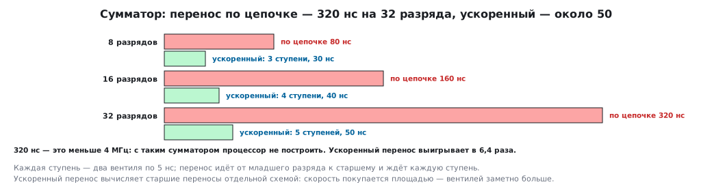
The price of simplicity is time. The carry passes through every stage:
| Bits | Delay (2 gates per stage, 5 ns each) |
|---|---|
| 8 | 80 ns |
| 16 | 160 ns |
| 32 | 320 ns |
Three hundred twenty nanoseconds is less than 4 MHz: you cannot build a fast processor
from logic chips with such an adder. Inside a die
gates are roughly a hundred times faster: the same adder takes about 3 ns, and for
72 MHz (a 13.9 ns cycle) even that would do. But at hundreds of megahertz the ripple
carry is the longest path in the adder. That is why fast cores use
carry-lookahead: the upper bits do not wait for the lower ones but compute
the carry with a separate circuit. The depth grows not linearly but logarithmically:
log₂(32) = 5 stages, about 50 ns instead of 320 — a gain of 6.4 times
at the cost of noticeably more gates.
This is a general rule of digital circuit design: speed is bought with area.
60.6 🔧 Expanding outputs with a shift register
A practical task: not enough pins. Eight LEDs driven directly take eight pins (and the whole current budget, section 49.7). A shift register does it with three. The current budget moves to the register: for the common 74HC595 output levels are guaranteed at about 6 mA, and through the package supply pins — no more than 70 mA. For bright LEDs you take a register with built-in current sinks or transistors on the outputs.
| Registers in a chain | Outputs | Microcontroller pins |
|---|---|---|
| 1 | 8 | 3 |
| 2 | 16 | 3 |
| 4 | 32 | 3 |
| 8 | 64 | 3 |
The three pins — data, clock and latch — stay the same no matter how many registers you add: the output of one goes to the input of the next.
It works like this: bits are shifted in one at a time by the clock signal, and then a latch pulse transfers everything to the outputs at once. The latch matters: without it the outputs would "wiggle" while bits are shifted in.
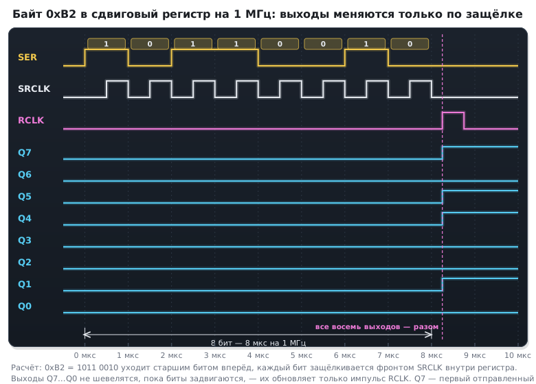
The cost is time. The bits go one after another:
| What we update | At 1 MHz | At 8 MHz |
|---|---|---|
| one register (8 outputs) | 8 µs | 1 µs |
| four registers (32 outputs) | 32 µs | 4 µs |
Even at 1 MHz a 32-output bar can be updated more than thirty thousand times per second — plenty for any display. The transfer is easy to hand to the hardware SPI (section 18) so that it costs no processor time at all.
60.7 🔧 Analog multiplexer in front of the ADC
The internal ADC channels may not be enough, or the sensors are far away. An external analog multiplexer connects one of eight sources to one input. Unlike a digital one, it passes voltage in both directions, and its closed channel has a resistance, usually about 100 Ω.
This resistance adds to the source resistance and lengthens the sampling (section 14.2):
| Source | Time constant | Required sampling time |
|---|---|---|
| 1 kΩ + 100 Ω channel | 5.5 ns | 46 ns |
| 1 kΩ without multiplexer | 5.0 ns | 42 ns |
| 100 kΩ + channel | 0.50 µs | 4.2 µs |
For 12 bits the sampling capacitor must charge to within one least significant bit — that is ln 4096 ≈ 8.3 time constants (to within half a bit — ln 8192 ≈ 9.0).
Conclusion: with a low-impedance source the multiplexer adds only four nanoseconds and does not get in the way. With a high-impedance source it is noticeable, and there you either put a buffer before the multiplexer (section 56.1) or set a long sampling time.
60.8 Pitfalls
A peripheral does not appear on the pin. The alternate function multiplexer is not configured, or another block is already assigned to the pin — exactly one is selected.
Unrelated outputs flash when the decoder address changes. The address lines do not change at the same instant; remove enable during the switch.
The wrong interrupt is served. With simultaneous requests the smaller priority value wins, and with equal values — the smaller interrupt number (section 7.3).
A zero at the encoder output cannot be told from no request. You need a separate flag.
LEDs on a shift register "run" during an update. The latch is not used — the outputs change while bits are shifted in.
Registers were added and updates became slow. The time grows linearly with the number of registers: calculate it from the clock frequency.
ADC readings through an external multiplexer "drift". Channel resistance plus a high-impedance source: increase the sampling time or add a buffer.
Adjacent multiplexer channels affect each other. Not enough sampling time — the capacitor remembers the previous channel (section 50.6).
60.9 Summary
- A combinational circuit has no memory: the output depends only on the current inputs.
- A multiplexer selects one input of
2ⁿ; this is exactly how pin alternate functions, clock selection and ADC channels work — and why two blocks cannot drive one pin at the same time. - A decoder activates exactly one output of
2ⁿ; the enable input is needed while the address changes. - A priority encoder returns the number of the highest request and a flag that a request is present — this is how an interrupt is chosen.
- An adder is built from half adders; it was checked on all 65536 pairs of bytes. Ripple carry over 32 bits gives 320 ns, carry-lookahead about 50: speed is bought with area.
- A shift register gives 8, 16, 64 outputs on the same three pins; the price is shift time, 32 µs for 32 outputs at 1 MHz.
- An analog multiplexer adds about 100 Ω to the source: with a low-impedance source that is 4 ns, with 100 kΩ it is already 4.2 µs of sampling.
Next: section 61 "Minimal circuit around the microcontroller: start-up conditions" — what must be on the board for the chip to start at all.