 Embedded HandbookApps
19. The CAN bus
A bus for links between devices, not between chips on one board. It was born in cars and has stayed there, and it is also used in industrial automation: anywhere nodes are metres apart, there is noise all around, and a message must get through.
Terms used in the documentation
Term Meaning transceiver the line driver/receiver chip between the controller and the bus dominant / recessive bit the bit that wins on the line / the bit that gives way arbitration deciding who keeps transmitting when nodes start together identifier the message identifier mailbox a transmit mailbox receive FIFO the receive queue acceptance filter a hardware receive filter bit timing how a bit is divided into time quanta sample point the moment the bit value is read bus-off the node is disconnected from the bus because of errors loopback mode self-test mode
19.1 How it differs from everything else
There is no master. Any node can start transmitting at any moment. Conflicts are resolved by arbitration, not by a schedule.
The message is addressed, not the device. A frame has no recipient — it has a topic identifier: "engine speed", "door state". Whoever wants it listens. You can add a new node without touching the existing ones.
A differential pair. Two wires carrying signals in antiphase. Noise couples into both equally and is subtracted — hence the robustness on long lines in an electrically dirty environment.
Error control is built into the hardware. Checksum, acknowledgement of reception, automatic retransmission on failure — the controller does all of this by itself.
19.2 ⚠️ A transceiver is mandatory
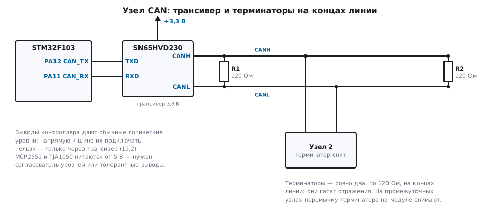
You cannot connect a microcontroller to a CAN bus directly. Its pins give ordinary logic levels, while the bus works as a differential pair with levels of a different standard.
A transceiver — a separate chip — goes between them:
| Transceiver | Supply |
|---|---|
| SN65HVD230 | 3.3 V — convenient for STM32 |
| MCP2551, TJA1050 | 5 V — needs a level shifter or tolerant pins |
Terminators. At both ends of the line — 120 Ω resistors. Not two anywhere, but exactly at the ends: they suppress reflections. One resistor or three instead of two — and the link works now and then, the worse the longer the line. Many ready-made modules have a terminator on the board and a jumper to disconnect it; on intermediate nodes it must be removed.
19.3 Arbitration: why the lower identifier wins
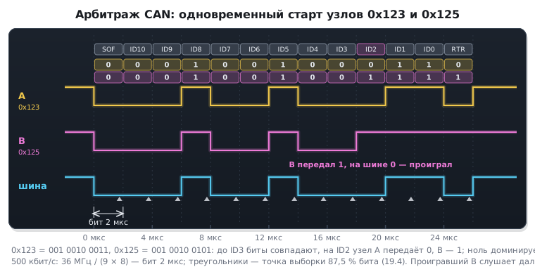
The bus logic is arranged so that zero dominates one: if one node transmits zero and another transmits one, the line carries zero.
All of arbitration follows from this. Having started transmitting at the same time, the nodes send their identifiers bit by bit and listen to the line at the same time. As soon as a node sees that it sent a one while the line shows a zero, it knows it has lost and quietly falls silent. The winner does not even know there was a conflict and continues transmitting without delay.
Practical conclusion: the lower identifier has the higher priority. When assigning message numbers, urgent things such as alarm signals get the low numbers, and telemetry goes to the high ones.
This is what arbitration of two nodes that started transmitting at the same time looks like on the screen of an analyzer connected to the outputs of both controllers and to the bus:
19.4 Bit timing
The most technical part of the setup. Each bit is divided into time quanta:
бит = 1 (синхронизация) + TS1 + TS2 квантов
скорость = частота шины / (BRP × (1 + TS1 + TS2))
The value is sampled at the boundary between TS1 and TS2 — this is the sample point.
Its position matters: too early, and the level on a long line has not settled yet;
too late, and there is no margin left for desynchronization.
The recommended value is about 87.5 % of the bit length.
Example for 500 kbit/s at 36 MHz:
BRP = 9, TS1 = 6, TS2 = 1  →  8 квантов на бит
36 000 000 / (9 × 8) = 500 000 бит/с
точка выборки = (1 + 6) / 8 = 87,5 %
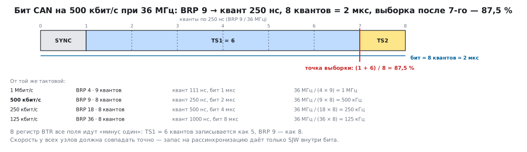
Other common rates from the same clock:
| Rate | BRP |
Quanta |
|---|---|---|
| 1 Mbit/s | 4 | 9 |
| 500 kbit/s | 9 | 8 |
| 250 kbit/s | 18 | 8 |
| 125 kbit/s | 36 | 8 |
The BTR register can be written only in initialization mode, and after reset the block
is also asleep (the SLEEP bit in MCR). The order is as follows:
CAN1->MCR &= ~CAN_MCR_SLEEP;              /* после сброса блок спит */
CAN1->MCR |= CAN_MCR_INRQ;                /* режим инициализации: BTR пишется только в нём */
for (timeout = 100000u; !(CAN1->MSR & CAN_MSR_INAK); timeout--) {
    if (timeout == 0u) {
        return 1u;
    }
}

CAN1->BTR = ((CAN_BRP - 1u) << 0)
          | ((CAN_TS1 - 1u) << 16)
          | ((CAN_TS2 - 1u) << 20)
          | ((CAN_SJW - 1u) << 24);

CAN1->MCR &= ~CAN_MCR_INRQ;               /* выход: ждёт 11 рецессивных бит подряд на RX */
for (timeout = 100000u; CAN1->MSR & CAN_MSR_INAK; timeout--) {
    if (timeout == 0u) {
        return 2u;                        /* на RX нет рецессивного уровня */
    }
}
The second wait ends only when 11 recessive bits in a row have passed on RX. If RX shows zero — the transceiver is not powered or not connected, or the wrong pin is selected (on the F103, CAN is on PA11 and PA12 by default, after remap — on PB8 and PB9) — without a timeout the program hangs here forever.
⚠️ All fields are encoded as "value minus one". If you want
TS1= 6 quanta, you write 5. Forget to subtract, and you get a different rate and a link that does not work, although the formula seems to be calculated correctly.
The "CAN" tab in the app's calculators picks BRP, TS1 and TS2 for
a given rate and clock, shows the sample point and the BTR word with the ones already
subtracted; you can check your own fields there as well.
⚠️ The rate must match exactly on all nodes. Unlike UART, where an error of a couple of percent is acceptable, here a mismatch leads to frame errors and the node leaving the bus.
How exactly — is calculated from the timing. The frequency tolerance of each node is
the smaller of two numbers: Δf ≤ TS2 / (2 · (13 · N − TS2)) and
Δf ≤ SJW / (20 · N), where N is the number of quanta per bit, and SJW is by how many quanta
the node adjusts the bit on an edge: from 1 to 4 and no more than TS2 (1 in the example).
The first formula is for TS2 no longer than TS1, as here. For the example
(8 quanta, TS2 = 1, SJW = 1) this gives 1 / 206 = 0.49 % and 1 / 160 = 0.63 %:
each node must be within 0.49 %. The internal HSI oscillator with its ±1 % cannot
achieve this — CAN is clocked from a crystal.
19.5 Receive filters
On a busy bus there are hundreds of messages per second, and sorting all of them in software is wasteful. The controller can discard the unneeded ones in hardware: before the processor learns about them.
A filter works in one of two modes:
- mask mode — accept everything that matches in the significant bits ("any message whose identifier starts with 0x1");
- list mode — accept only the listed identifiers.
void can1_filter_accept_all(void)
{
    CAN1->FMR |= CAN_FMR_FINIT;           /* фильтры в режим настройки */

    CAN1->FA1R &= ~(1u << 0);             /* банк выключить на время правки */
    CAN1->FS1R |= (1u << 0);              /* один 32-битный фильтр */
    CAN1->FM1R &= ~(1u << 0);             /* режим маски */

    CAN1->sFilterRegister[0].FR1 = 0;     /* идентификатор — любой */
    CAN1->sFilterRegister[0].FR2 = 0;     /* маска нулевая: всё равно */

    CAN1->FFA1R &= ~(1u << 0);            /* складывать в очередь 0 */
    CAN1->FA1R |= (1u << 0);              /* банк включить */

    CAN1->FMR &= ~CAN_FMR_FINIT;
}
⚠️ Without a configured filter, nothing is received. This is the first thing people trip over: transmission works, but reception is silent. By default the controller rejects all messages, and "accept everything" must be set explicitly.
19.6 Transmission
Three transmit mailboxes: you can queue three messages, then you have to wait. Reception goes into two FIFOs of three messages each.
uint8_t can1_send(uint16_t id, const uint8_t *data, uint8_t len)
{
    uint8_t box;

    if (len > 8u) {
        return 1u;                        /* в кадр помещается максимум 8 байт */
    }

    if (CAN1->TSR & CAN_TSR_TME0)      box = 0u;
    else if (CAN1->TSR & CAN_TSR_TME1) box = 1u;
    else if (CAN1->TSR & CAN_TSR_TME2) box = 2u;
    else return 2u;                       /* все заняты */

    CAN1->sTxMailBox[box].TIR = ((uint32_t)id << 21);   /* 11-битный номер */
    CAN1->sTxMailBox[box].TDTR = len;
    /* ... данные в TDLR и TDHR ... */
    CAN1->sTxMailBox[box].TIR |= CAN_TI0R_TXRQ;        /* запрос передачи */
    return 0u;
}
Eight bytes per frame is a hard limit of classic CAN. More data is split into several messages, and for transferring long blocks there are protocols on top of the bus.
19.7 Errors and leaving the bus
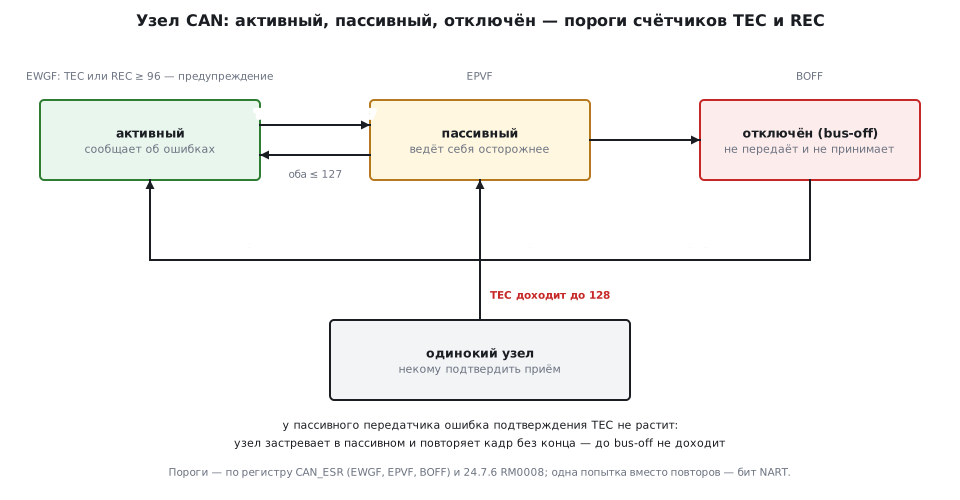
The controller keeps transmit and receive error counters. The logic is as follows:
| State | What it means |
|---|---|
| active | everything is fine, the node reports errors normally |
| passive | many errors have accumulated, the node behaves more cautiously |
| bus-off | too many errors, the node is disconnected from the bus |
Going bus-off protects the bus from a faulty node: a broken transmitter must not paralyze everyone else. Recovery is either manual or automatic — if the corresponding bit is set:
CAN1->MCR |= CAN_MCR_ABOM; /* восстанавливаться автоматически */
The most common beginner's trap is a lone node on the bus. The transmitter
waits for an acknowledgement from at least one listener; if there is nobody else
on the line, there will be no acknowledgement. The transmit error counter grows
to 128, and the node becomes passive. From then on, by the rules of the standard, an acknowledgement
error of a passive transmitter does not increase the counter: the node does not go
bus-off but repeats the frame endlessly. If you need a single attempt, use the
NART bit in CAN_MCR (no automatic retransmission). Real errors take a node bus-off:
different node rates, swapped CANH and CANL, missing terminators.
Hence the useful self-test mode (loopback): the controller listens to its own transmissions and acknowledges them to itself. It lets you debug code and check timing with a single board and no transceiver at all.
19.8 ⚠️ An F103 quirk: CAN and USB do not get along
On the STM32F103, the CAN and USB controllers share a common memory for message buffers — 512 bytes. They cannot work at the same time: either one or the other is used.
On the BluePill this is noticeable: the USB connector is routed there, and if the project is designed with a USB interface, CAN has to be dropped, and vice versa. The F105/F107 connectivity line solves this problem — there the controllers are independent, as on the F4.
19.9 Pitfalls
No transceiver. A direct connection to the bus does not work and can damage the pins.
Wrong terminators. Exactly two of 120 Ω, exactly at the ends of the line.
Timing fields not reduced by one. The rate comes out different.
No filter configured. Reception is silent while transmission works.
A lone node repeats the frame endlessly. There is no second participant, nobody to acknowledge reception: the node is passive but not bus-off. For debugging — self-test mode.
Node rates do not match. CAN does not forgive mismatches the way UART does.
CAN and USB at the same time on the F103. It will not work, the memory is shared.
Ground not connected. The differential pair helps against noise, but a common potential is still needed.
19.10 Summary
- CAN links devices, not chips: a differential pair, noise immunity, hardware error control.
- A transceiver is mandatory; 120 Ω terminators — exactly two, at the ends of the line.
- The message is addressed, not the recipient; the lower identifier has the higher priority.
- Bit timing is set in quanta, the sample point is about 87.5 %; all fields are encoded with an offset of one.
- Without an explicitly configured filter, reception does not work.
- A frame holds at most 8 bytes.
- A lone node on the bus does not go bus-off but becomes passive and repeats the frame endlessly — for debugging there is self-test mode, which works without a transceiver.
- On the F103, CAN and USB use a common memory and are not available at the same time.
Next: section 19а "CAN FD on FDCAN: 64 bytes, two bit rates, message RAM".