 Embedded HandbookApps
57к. 28BYJ-48 stepper and ULN2003: full-step and half-step modes, timer-driven acceleration
In 57а the stepper motor was bipolar: two windings, current in each flows both ways, so every winding needs a bridge. In 57е that current was held by a chopper, and in 57ж a tiny gauge motor managed with no driver at all. Here is the cheapest stepper from the hobby kits: the 28BYJ-48 5 V gear motor with a ULN2003 board. It is unipolar: each winding has a centre tap, and current in a half-winding always flows the same way. No bridge is needed — four switches to ground are enough.
What is inside: how the four phases and the common wire are arranged; why
the gearbox ratio is 63.68 and not 64, and where the error goes if you
count 4096 half-steps per revolution; three commutation tables and why all
four pins must change in one write to BSRR; what the ULN2003 is and how
much is lost in it; up to what rate the motor starts from standstill
without acceleration and what a missed step looks like; a trapezoidal
acceleration from a TIM2 interrupt with an interval table; when to keep
the current on and when to switch it off, and what to do about backlash.
Sources: RM0008 (DocID13902 Rev 17): atomic bit set and reset, 9.1.2,
p. 160; the GPIOx_BSRR register, p. 172. DocID13587 Rev 17
(STM32F103x8/xB): PB12–PB15 are 5 V tolerant, p. 30; 25 mA per pin and
150 mA for all pins, table 7, p. 37. AN3208 Rev 1 (Doc ID 17411), p. 5: a
unipolar winding is two coils with a centre tap, a bipolar one gives more
torque because the whole coil carries current. Harris and Harris, «Digital
Design and Computer Architecture» (Russian edition), pp. 330–332: a
unipolar motor is driven by simple switches; wave, two-phase and half-step
drive; with direct voltage drive the current cannot rise at high speed.
The Zephyr 4.4.2 driver drivers/stepper/gpio_stepper/h_bridge_stepper_ctrl.c
— the same 8-step half-step table, full step every other step; its binding
describes «darlington transistor arrays». The project has no documents on
the 28BYJ-48 or the ULN2003: the gear tooth counts, 50 Ω and 5 V are
typical values as given by sellers and teardowns, not verified. All
numbers below come from a run of the driver _verify/step57k/byj57k.c,
built by arm-none-eabi-gcc 12.2 for the Cortex-M3 and run in QEMU 7.2, and
from a Python 3.11 motor model that turns the rotor with that very phase
sequence. The ULN2003 channel is simulated in ngspice-39. The rotor and
winding parameters of the model are nominal; what matters is not the
rates themselves but how the modes compare.
What it is called in the documentation
Original Meaning unipolar, bipolar stepper unipolar (half-windings with a centre tap), bipolar stepper centre tap, common wire centre tap, common wire gear ratio, gearbox, backlash gear ratio, gearbox, backlash stride angle step angle of the output shaft wave drive, two-phase on (full step), half step wave drive, full step (two phases), half step Darlington transistor array array of Darlington compound transistors clamp (freewheeling) diode, COMdiode for the winding current after switch-off, common cathode of the diodes saturation voltage VCE(sat)voltage across a closed switch atomic bit set/reset, GPIOx_BSRRatomic set and reset of pins start-stop (pull-in) rate rate at which the motor starts without acceleration pull-out rate rate at which an accelerated motor falls out of step trapezoidal velocity profile speed trapezoid: acceleration, run, deceleration holding torque holding torque missed (lost) step missed step
57к.1 Motor, board and gearbox: 63.68, not 64
The 28BYJ-48 housing holds two windings, each with a centre tap. The taps are joined and brought out as a common wire to +5 V. The other four ends are the four phases A, B, C, D, one per ULN2003 switch: closing a switch lets current flow through a half-winding to ground. A and C are halves of one winding, their fields point against each other; B and D are halves of the other. Switching A and C on together is pointless: the fields cancel.
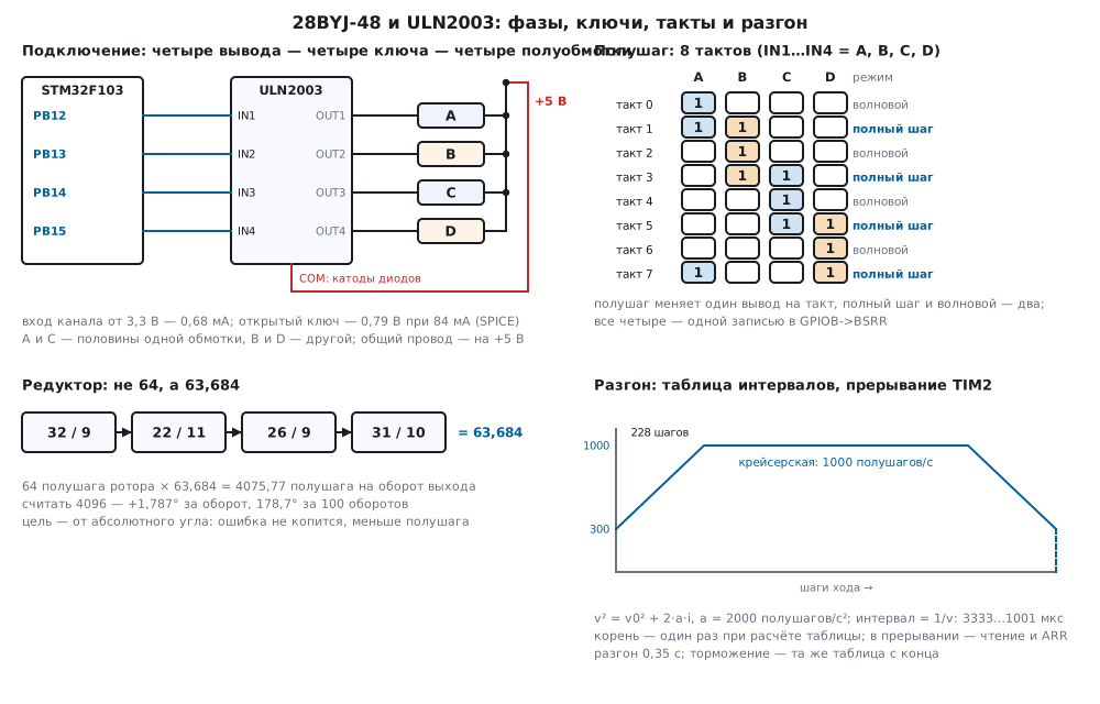
The rotor is a permanent magnet. One full turn of the field is four full steps, and a rotor revolution has 32 of them: in the model that is eight pole pairs, 64 half-steps per rotor revolution. Then come four gear stages. People often write «64:1» and «4096 half-steps per output revolution», but the tooth counts given by teardowns of this gearbox say otherwise:
| Stage | 1 | 2 | 3 | 4 | Total |
|---|---|---|---|---|---|
| teeth | 32 / 9 | 22 / 11 | 26 / 9 | 31 / 10 | 283712 / 4455 |
| ratio | 3.556 | 2 | 2.889 | 3.1 | 63.684 |
The exact number is 63.68395. One output revolution is 4075.7728 half-steps, or 2037.8864 full steps; one half-step turns the output by 0.08833°. There is no whole number of steps per revolution at all.
Where the error goes. If you count 4096 half-steps per revolution, each «revolution» is really 1.787° longer. The error accumulates:
| Revolutions | Half-steps «at 4096» | Error | Exact target | Error |
|---|---|---|---|---|
| 1 | 4096 | 1.787° | 4076 | 0.020° |
| 10 | 40960 | 17.866° | 40758 | 0.024° |
| 100 | 409600 | 178.660° | 407577 | −0.025° |
In a hundred revolutions a pointer, drum or valve drifts half a turn. Rounding to 4076 and adding it every revolution is better but still accumulates: +0.0201° per revolution, 2.01° per hundred. The right way is to compute the target from the absolute angle, as a rational number, and only then round:
/* Угол выходного вала в сотых долях градуса → полушаги, с округлением, без накопления ошибки:
 * 4075,77 полушага на оборот = 64 · 283712 / 4455. */
int32_t byj_cdeg_to_half(int32_t cdeg)
{
    int64_t num = (int64_t)cdeg * (int64_t)(BYJ_HALF_ROTOR * BYJ_GEAR_NUM);
    int64_t den = (int64_t)BYJ_GEAR_DEN * 36000;
    return (int32_t)(num >= 0 ? (num + den / 2) / den : -((-num + den / 2) / den));
}
1° is 11 half-steps, 90° is 1019, one revolution is 4076, a hundred
revolutions are 407577; each target is off by less than half a half-step,
however many revolutions came before it. The product of 18 157 568 and an
angle in hundredths of a degree does not fit in 32 bits — hence int64_t.
If your unit has other gears, two constants change, BYJ_GEAR_NUM and
BYJ_GEAR_DEN; checking is simple — a hundred revolutions and a mark on
the shaft.
57к.2 Three step tables and a single write to BSRR
The order of states sets the direction of the field. In the model the field of each phase is turned by 90 electrical degrees: A — 0°, B — 90°, C — 180°, D — 270°. The half-step table has eight states, and the field turns by 45° on each:
| State | 0 | 1 | 2 | 3 | 4 | 5 | 6 | 7 |
|---|---|---|---|---|---|---|---|---|
| phases | A | AB | B | BC | C | CD | D | DA |
| mask IN4…IN1 | 0001 | 0011 | 0010 | 0110 | 0100 | 1100 | 1000 | 1001 |
| mode | wave | full | wave | full | wave | full | wave | full |
Even states are wave drive: one phase, four states per field turn. Odd
ones are full step: two neighbouring phases, the field halfway between
them and √2 times stronger. All eight in a row are half step: the step
is half as large, but the torque swings between one phase and two. The
Zephyr driver is built the same way: one 8-state table, full step every
other state (lut-step-gap = 2). Its phase order A, B, C, D is the same.
/* Полушаг, 8 тактов; бит 0 — IN1 (A), бит 1 — IN2 (B), бит 2 — IN3 (C), бит 3 — IN4 (D).
 * Чётные такты — одна фаза (волновой режим), нечётные — две (полный шаг). */
static const uint8_t half_tab[8] = {0x1u, 0x3u, 0x2u, 0x6u, 0x4u, 0xCu, 0x8u, 0x9u};
The driver keeps the position in half-steps in every mode: in half-step mode a step is ±1, in the others ±2. So the mode can change between moves without losing count.
One write per state. In half-step mode one pin changes from state to
state, in full step and wave drive — two. If the pins are written one at a
time, as a loop over gpio_pin_set_dt in Zephyr or four pin-write calls
do, the port passes through intermediate states between the writes. The
bench wrote the states one pin at a time in the order IN1…IN4:
| Mode | Transitions | With an intermediate state | What is in between |
|---|---|---|---|
| half step | 8 | 0 | — |
| full step | 4 | 4 | in two of four — both halves of one winding (A + C + D, A + B + D) |
| wave | 4 | 4 | in three — all phases off, in one — D and A |
Both halves of one winding at once — their fields cancel, and the current
at that moment is wasted. It does not last long, but the state should not
exist at all. The BSRR register solves it with one write: the low 16 bits
set pins, the high ones reset them, and it is all one atomic bus access
(RM0008, 9.1.2, p. 160), without disabling interrupts. If one word holds
both a set and a reset of the same pin, the set wins (p. 172).
/* Одно слово BSRR: включённые фазы — в BS, выключенные — в BR. Все четыре вывода меняются одной записью. */
uint32_t byj_bsrr(uint8_t mask)
{
    uint32_t on = (uint32_t)(mask & 0xFu), off = (uint32_t)(~mask & 0xFu);
    return on << BYJ_PIN0 | off << (BYJ_PIN0 + 16u);
}
For PB12…PB15 the words are: state A — 0xE0001000, AB — 0xC0003000, all
off — 0xF0000000. A second benefit of atomicity: an LED or another pin of
the same port touched by the main loop cannot be upset by the step
interrupt; with a read-modify-write of ODR that can happen.
57к.3 ULN2003: Darlington switches, diodes to COM, current and heat
The ULN2003 is an array of Darlington compound transistors (170а.1) with
open collectors: several channels in one package, each with an input
resistor and a diode from the output to the common pin COM, emitters to
ground (170а.8 recommends such arrays precisely for inductive loads). The
number of channels and the pinout follow the manufacturer documentation.
A channel input turns on from a logic one, and the switch pulls its
half-winding to ground. The model takes the typical channel circuit:
2.7 kΩ at the input, 7.2 kΩ from the base of the first transistor to
ground, 3 kΩ for the second; the values follow the manufacturer
documentation, which is not on disk. The transistors are the NPN model from
section 170.
A channel driven from a 3.3 V pin, a 50 Ω half-winding from 5 V, in SPICE:
| What | Value |
|---|---|
| half-winding current | 84.2 mA |
| voltage across a closed switch | 0.792 V |
| input current from the MCU pin | 0.683 mA |
| heat in one switch | 0.0667 W |
| the same, two phases | 0.133 W |
The switch does not saturate to zero: a compound transistor keeps the base-emitter voltage of the second transistor across itself (170а.1). At 50, 200, 300 and 500 mA the model gives 0.769, 0.850, 0.894 and 0.980 V. Of the 5 V the winding gets 4.2 V — hence 84 mA instead of 100.
The ULN2003 input hardly loads the pin: 0.683 mA against 25 mA per pin and 150 mA for all (DocID13587, table 7, p. 37). Pins PB12…PB15 are also 5 V tolerant (p. 30), but that is not needed here — the ULN2003 turns on from 3.3 V.
Diodes and COM. A half-winding is an inductance. When the switch opens,
the current cannot stop at once: it goes through the channel diode to
COM. If COM is tied to +5 V, the output rises a little above the supply —
to 5.83 V in the model — and the current falls to 10 % in 0.871 ms; the L/R
time constant of a half-winding in the model is 0.60 ms. Without COM the
current has no path, and the voltage across the switch rises to breakdown
(51.2 — a clamp diode for any coil): each switch-off dumps ½·L·I² =
0.106 mJ into the switch, and at 1000 half-steps/s that is 500 switch-offs a
second. On a ready-made board check where COM goes; on a breadboard it is
forgotten.
Current and heat. Two phases on take 168.3 mA from the 5 V supply: 0.708 W in the windings and 0.133 W in the ULN2003, 0.841 W in total. One phase — half that, 0.421 W. And not only while moving: a standing motor with its phases on heats up just the same (57к.6).
57к.4 Step rate: where the motor falls out without acceleration
With the winding fed straight from 5 V it is an L/R circuit: the current does not rise at once, and at high speed it cannot reach its full value (Harris and Harris, p. 332). The rotor with its gearbox also needs time to catch up with the field. If you step fast right from standstill, the rotor does not keep up, the field runs ahead by more than half an electrical turn, and the rotor is pulled back. The motor hums and stands still.
The model: a 50 Ω, 30 mH half-winding (the inductance is nominal), a
permanent-magnet rotor with eight pole pairs, inertia, dry and viscous
friction — nominal; the switch drops 0.792 V from SPICE, after switch-off
the current flows through the diode to COM. The driver steps from
standstill at a constant rate; after the move the phases stay on for
another 100 ms, and the rotor position is compared with the command. A lag
below 2 half-steps is friction holding the rotor slightly off the state,
not a missed step.
| Mode | Starts | Falls out | Output speed at the limit |
|---|---|---|---|
| wave | 225 steps/s | 250 steps/s | 6.62 rpm |
| full step | 300 steps/s | 350 steps/s | 8.83 rpm |
| half step | 550 half-steps/s | 600 half-steps/s | 8.10 rpm |
| half step, 4.5 V | 500 half-steps/s | 550 half-steps/s | 7.36 rpm |
Wave drive is the weakest: one phase, √2 times less torque. Full step and half step start at almost the same rotor speed, but the half step is half as large. At 4.5 V instead of 5 — as happens on USB power through the board diode — the threshold is lower: less current, and less torque.
What a missed step looks like. A motor that falls out at the start does not skip part of the move — it stands still for nearly all of it. Half step at 600/s: of 256 half-steps, 216 are not made. And one more thing: in all 21 fall-outs of the run the lag is a multiple of 8 half-steps. The rotor slips not by one step but by a whole field turn — four full steps — and settles in the same state. So the firmware never learns about the miss: the state is the same, the count goes on. Only a sensor on the shaft can tell — for example the AS5600 from 57и.
57к.5 Trapezoidal acceleration from a TIM2 interrupt
To go faster than the motor starts from standstill, the speed is raised gradually — as a trapezoid: acceleration at constant rate, run, deceleration. For a constant acceleration a, the speed at step i from the start of acceleration is v² = v0² + 2·a·i, and the interval to the next step is 1/v. In 57а.4 the intervals came from a recurrence formula with a first-step correction. Here it is simpler: a table of intervals once at start-up, and in the interrupt — only a read.
/* Трапеция: на i-м шаге разгона v² = v0² + 2·a·i (шагов/с, шагов/с²), интервал = 1 / v в мкс.
 * Корень считается здесь, один раз на шаг таблицы, — в прерывании только чтение таблицы. */
uint32_t byj_ramp_init(byj_ramp_t *r, uint32_t v0, uint32_t vmax, uint32_t acc)
{
    uint32_t i = 0;
    while (i < BYJ_RAMP_MAX) {
        uint64_t v2 = (uint64_t)v0 * v0 + 2u * (uint64_t)acc * i;
        uint32_t vq = isqrt64(v2 << 16);                  /* скорость × 256 */
        if (vq >= vmax * 256u)
            break;
        r->ramp[i++] = (uint16_t)((256000000u + vq / 2u) / vq);
    }
    r->n_acc = (uint16_t)i;
    r->c_run = (uint16_t)((1000000u + vmax / 2u) / vmax);
    if (i == BYJ_RAMP_MAX)
        r->c_run = r->ramp[i - 1u];                      /* таблица кончилась раньше vmax: дальше — её скорость */
    return i;
}
The firmware goes from 300 to 1000 half-steps/s, a = 2000 half-steps/s².
The table has 228 intervals, 456 bytes: from 3333 down to 1001 µs, the run
interval is 1000 µs. The model compared each interval with the exact
formula: the difference is at most 0.502 µs — rounding to a whole
microsecond. Acceleration by the table takes 0.3517 s, by the formula
(vmax − v0)/a — 0.35 s. The last line of byj_ramp_init is a safeguard: if
the table runs out before the run speed, the move continues at the speed of
its end instead of jumping to vmax.
Deceleration is the same table from the end. The interval number is counted from the nearer end of the move, so a short move that never reaches full speed becomes a triangle without a jump:
/* Интервал перед (j+1)-м шагом: k — шагов до ближнего края хода; разгон и торможение — одна таблица. */
static uint32_t interval(const byj_t *m, uint32_t j)
{
    uint32_t k = m->total - 1u - j < j ? m->total - 1u - j : j;
    return k < m->r->n_acc ? m->r->ramp[k] : m->r->c_run;
}
/* Прерывание таймера: следующий такт, одна запись в порт, интервал до следующего шага (0 — ход окончен). */
uint32_t byj_isr(byj_t *m)
{
    if (!m->left)
        return 0u;
    uint8_t d = m->mode == BYJ_HALF ? 1u : 2u;
    m->idx = (uint8_t)((m->idx + (m->dir > 0 ? d : 8u - d)) & 7u);
    m->pos += m->dir * (int32_t)d;
    byj_port_write(byj_bsrr(byj_mask(m->idx)));
    m->done++;
    if (--m->left == 0u)
        return 0u;
    return interval(m, m->done);
}
TIM2 ticks once per 1 µs (PSC = 71 at 72 MHz), the update interrupt makes
a step and writes the new ARR. ARR preload is off: the counter has just
started from zero, the new ARR is certainly larger than CNT and takes
effect at once — the trap of wrapping through 65 535 from 13.4 does not
arise here. The intervals fit in 16 bits: the longest in the firmware is
3333 µs.
void TIM2_IRQHandler(void)
{
    TIM2->SR = (uint16_t)~TIM_SR_UIF;
    uint32_t c = byj_isr(&mot);
    if (c) {
        TIM2->ARR = c - 1u;
    } else {
        TIM2->CR1 &= (uint16_t)~TIM_CR1_CEN;
        busy = 0;
    }
}
One output revolution in the firmware is 4076 half-steps in 4.3233 s, 3620 of them at run speed; the bench log matched the table exactly, and the move is symmetric. What acceleration gives in the model (a move of 2048 steps):
| Mode, acceleration | Reached without a miss | Fell out | Output speed at the limit |
|---|---|---|---|
| half step, 2000 half-steps/s² | 1300 half-steps/s | 1400 half-steps/s | 19.14 rpm |
| full step, 1000 steps/s² | 700 steps/s | 800 steps/s | 20.61 rpm |
| half step, 2000 half-steps/s², 4.5 V | 1000 half-steps/s | 1200 half-steps/s | 14.72 rpm |
Without acceleration the half step started up to 550/s; with it, it reaches 1300/s — 2.4 times faster. At speed full step is stronger than half step: always two phases, a smoother torque. A motor that falls out while running again simply stops: at 1400/s, 1464 of 2048 half-steps are not made.
Acceleration is not unlimited either. Up to 1000 half-steps/s from 300:
| Acceleration, half-steps/s² | 2000 | 5000 | 10 000 | 20 000 | 50 000 |
|---|---|---|---|---|---|
| move of 2048 half-steps | 2.295 s | 2.148 s | 2.099 s | 2.075 s | falls out |
From 2000 to 20 000 the move is only 0.22 s shorter: nearly all the time is the run section. Taking the acceleration with a margin from the limit is cheap.
57к.6 Holding, switching phases off, and backlash
Keep or remove the current. After a move the rotor is held by the phases of the last state. Two phases — 0.841 W and in the model 30.3 mN·m at the output, one — 0.421 W and 21.4 mN·m (the model torque with an ideal gearbox is nominal). An hour of holding is 0.84 Wh of heat into the motor and the ULN2003, while they do nothing. Without current the output is held only by gearbox friction (in the model, dry friction at the rotor; how much a real motor holds is not verified). If the load is light, the usual way is: hold for half a second after the move so the rotor settles, then remove the current:
/* Снять ток со всех фаз: держит только трение редуктора. Такт idx запомнен — byj_move подаст его же. */
void byj_release(byj_t *m)
{
    byj_port_write(byj_bsrr(0u));
    m->on = 0;
}
It matters which state the next move starts from. byj_move first powers
the same state the motor stopped in, and only then steps: the bench checked
that the first write of the return move matched the last write of the
forward move. Power a different state, and the rotor jumps to it. After an
MCU reset the state is unknown; the model: the rotor stood in state 1…7,
the firmware powers state 0:
| Stood in state | 1 | 2 | 3 | 4 | 5 | 6 | 7 |
|---|---|---|---|---|---|---|---|
| jump, half-steps | −1.48 | −2.34 | −2.84 | 0 | 2.84 | 2.34 | 1.48 |
| at the output | −0.130° | −0.207° | −0.251° | 0 | 0.251° | 0.207° | 0.130° |
State 4 is the opposite one: the field pulls the rotor straight back, and it sits in an unstable equilibrium; in the model it stayed in place, in reality it goes 4 half-steps either way — 0.353°. The gearbox divides the jump by 63.7, so at the output these are fractions of a degree; but after a reset the zero is searched for again anyway — with a limit switch or a sensor.
Backlash. There is play between the gears: when the direction changes, the rotor first takes it up while the output stands still. In the model the backlash is 1.0° at the output (nominal; measure your own unit). A move of 90° forward ended −0.457° from the target, the move back to zero at +0.456°: the same point approached from two sides differs by 0.913°. The cure is to always approach the target from one side. If the target is lower, first go below it by a margin larger than the backlash, then approach from below:
/* Люфт: к цели всегда подходим в одну сторону (вверх). Если цель ниже — сначала на backlash ниже неё.
 * Возвращает число ходов (1 или 2), *via — точка первого хода. */
int32_t byj_plan(int32_t pos, int32_t target, int32_t backlash, int32_t *via)
{
    if (target >= pos || backlash <= 0) {
        *via = target;
        return 1;
    }
    *via = target - backlash;
    return 2;
}
With a margin of 24 half-steps (2.12°) the return to zero ended at −0.448° — just like the forward move (−0.457°): the constant offset is removed by setting the zero, and the spread between directions is 0.009° instead of 0.913°.
57к.7 Pitfalls
The motor trembles in place or jerks. The phases are connected in the wrong order — the board connector is keyed, but with your own wiring or in code (PB12, PB14, PB13, PB15) they get mixed up. In the model, at full step 150 steps/s with IN1 and IN2 swapped, the rotor stands and trembles (a swing of 0.1 half-step), with IN2 and IN3 swapped it moved 15.2 half-steps of 256. In half-step mode the same mistake behaves differently: IN1 ↔ IN2 — the motor honestly runs backwards (−256.4), IN2 ↔ IN3 — it goes back by 239.9 half-steps. Check the order slowly, one state at a time, watching the shaft.
On USB the motor is weak and falls out. USB power, especially through the board diode, can be noticeably below 5 V. In the model at 4.5 V the start threshold drops from 550 to 500 half-steps/s, and the limit with acceleration from 1300 to 1000. And a USB port is not meant for motors: 168 mA for two phases plus noise from switching windings off on the ground shared with the MCU. Power the motor from a separate 5 V supply, with a common ground.
COM is not connected to +5 V. The half-winding current is cut off at
switch-off, and the energy of 0.106 mJ per switch-off goes into the switch
breakdown. The motor still turns, but the ULN2003 heats up and fails. COM —
to the same +5 V as the motor common wire.
It heats up while standing. The phases are on after the move: 0.841 W
with two phases. Remove the current half a second after the move
(byj_release) or hold one phase.
After a hundred revolutions the position drifted by half a turn. Counting 4096 half-steps per revolution: +1.787° per revolution, 178.66° per hundred. Compute the target from the absolute angle through 283712/4455 (57к.1).
The motor hums and does not start. The starting rate is above the threshold: in the model half step falls out from 600/s. Start slower and accelerate along the table.
After a reset the shaft jerked. The firmware powered a state other than
the one the rotor stood in. During operation, power the same state before
a move (as byj_move does); after a reset the zero is searched for again.
Two halves of a winding at once when changing state. The pins are
written one by one: at full step two transitions of four pass through both
halves of one winding. One write to BSRR.
It reaches the target sometimes from one side, sometimes from the
other. Backlash: 0.913° between directions in the model. Always approach
from below (byj_plan).
57к.8 Summary
- The 28BYJ-48 is a unipolar gear motor: four half-windings A, B, C, D on
ULN2003 switches, the common wire and
COMto +5 V; A and C, B and D are halves of one winding. - The gearbox is 283712/4455 = 63.684, not 64: 4075.77 half-steps per revolution. Counting 4096 drifts by 1.787° per revolution and by 178.66° per hundred; a target from the absolute angle is off by less than a half-step.
- An 8-state half-step table: even states are wave drive, odd ones full
step. All four pins in one write to
BSRR; one at a time, at full step two transitions of four pass through both halves of a winding. - The ULN2003 in the model: 0.792 V across a closed switch at 84.2 mA, the input takes 0.683 mA from a 3.3 V pin; two phases take 168.3 mA and give 0.841 W of heat.
- Without acceleration in the model: half step starts up to 550/s, full step up to 300/s, wave drive up to 225/s; a miss is always a multiple of 8 half-steps, and the firmware does not know about it.
- A trapezoid from a table: 228 intervals, 456 bytes, the root only when building it; with acceleration half step reaches 1300/s, full step 700/s.
- Remove the current after a move; start the next move from the same state; approach the target from one side — the backlash spread is 0.009° instead of 0.913°.
Full sources
byj57k.h — pins, modes, gearbox, driver types and prototypes.
/* byj57k.h — раздел 57к: шаговый мотор-редуктор 28BYJ-48 через ULN2003, без регистров микроконтроллера.
 * Четыре фазы IN1…IN4 — подряд на выводах одного порта, начиная с BYJ_PIN0; выдача — словом BSRR через
 * порт byj_port_write: в прошивке fw57k.c это GPIOB->BSRR, на стенде qemu57k.c — запись в журнал.
 * Код один для прошивки и стенда. */
#ifndef BYJ57K_H
#define BYJ57K_H
#include <stdint.h>

#define BYJ_PIN0        12u         /* IN1 — PB12, IN2 — PB13, IN3 — PB14, IN4 — PB15 */

#define BYJ_WAVE        0u          /* одна фаза: A, B, C, D */
#define BYJ_FULL        1u          /* две фазы: AB, BC, CD, DA */
#define BYJ_HALF        2u          /* полушаг: 8 тактов */

/* Редуктор: (32/9)·(22/11)·(26/9)·(31/10) = 283712 / 4455 ≈ 63,684 — не 64.
 * Ротор — 64 полушага на оборот; выходной вал — 64 · 283712 / 4455 ≈ 4075,77 полушага. */
#define BYJ_GEAR_NUM    283712u
#define BYJ_GEAR_DEN    4455u
#define BYJ_HALF_ROTOR  64u

#define BYJ_RAMP_MAX    1024u       /* интервалов в таблице разгона: 2 КБ ОЗУ */

void byj_port_write(uint32_t bsrr);

typedef struct {
    uint16_t ramp[BYJ_RAMP_MAX];    /* интервал i-го шага разгона, мкс */
    uint16_t n_acc;                 /* шагов до крейсерской скорости */
    uint16_t c_run;                 /* крейсерский интервал, мкс */
} byj_ramp_t;

typedef struct {
    const byj_ramp_t *r;
    int32_t pos;                    /* положение в полушагах */
    uint32_t left, done, total;     /* шагов осталось, сделано, всего */
    uint8_t mode, idx;              /* режим, такт 0…7 таблицы полушага */
    int8_t dir;                     /* +1 или −1 */
    uint8_t on;                     /* фазы под током */
} byj_t;

uint8_t byj_mask(uint8_t idx);
uint32_t byj_bsrr(uint8_t mask);
void byj_init(byj_t *m, uint8_t mode);
uint32_t byj_ramp_init(byj_ramp_t *r, uint32_t v0, uint32_t vmax, uint32_t acc);
uint32_t byj_move(byj_t *m, const byj_ramp_t *r, int32_t steps);
uint32_t byj_isr(byj_t *m);
void byj_release(byj_t *m);
int32_t byj_cdeg_to_half(int32_t cdeg);
int32_t byj_plan(int32_t pos, int32_t target, int32_t backlash, int32_t *via);

#endif
byj57k.c — step table, BSRR word, acceleration table, step in the interrupt, gearbox and backlash — shared by the firmware and the bench.
/* byj57k.c — раздел 57к: таблицы фаз, слово BSRR, трапеция разгона, шаг в прерывании, редуктор и люфт. */
#include "byj57k.h"

/* Полушаг, 8 тактов; бит 0 — IN1 (A), бит 1 — IN2 (B), бит 2 — IN3 (C), бит 3 — IN4 (D).
 * Чётные такты — одна фаза (волновой режим), нечётные — две (полный шаг). */
static const uint8_t half_tab[8] = {0x1u, 0x3u, 0x2u, 0x6u, 0x4u, 0xCu, 0x8u, 0x9u};

uint8_t byj_mask(uint8_t idx)
{
    return half_tab[idx & 7u];
}

/* Одно слово BSRR: включённые фазы — в BS, выключенные — в BR. Все четыре вывода меняются одной записью. */
uint32_t byj_bsrr(uint8_t mask)
{
    uint32_t on = (uint32_t)(mask & 0xFu), off = (uint32_t)(~mask & 0xFu);
    return on << BYJ_PIN0 | off << (BYJ_PIN0 + 16u);
}

void byj_init(byj_t *m, uint8_t mode)
{
    m->r = 0;
    m->pos = 0;
    m->left = m->done = m->total = 0;
    m->mode = mode;
    m->idx = mode == BYJ_FULL ? 1u : 0u;
    m->dir = 1;
    m->on = 0;
}

static uint32_t isqrt64(uint64_t x)
{
    uint64_t r = 0, b = (uint64_t)1 << 62;
    while (b > x)
        b >>= 2;
    while (b) {
        if (x >= r + b) {
            x -= r + b;
            r = (r >> 1) + b;
        } else {
            r >>= 1;
        }
        b >>= 2;
    }
    return (uint32_t)r;
}

/* Трапеция: на i-м шаге разгона v² = v0² + 2·a·i (шагов/с, шагов/с²), интервал = 1 / v в мкс.
 * Корень считается здесь, один раз на шаг таблицы, — в прерывании только чтение таблицы. */
uint32_t byj_ramp_init(byj_ramp_t *r, uint32_t v0, uint32_t vmax, uint32_t acc)
{
    uint32_t i = 0;
    while (i < BYJ_RAMP_MAX) {
        uint64_t v2 = (uint64_t)v0 * v0 + 2u * (uint64_t)acc * i;
        uint32_t vq = isqrt64(v2 << 16);                  /* скорость × 256 */
        if (vq >= vmax * 256u)
            break;
        r->ramp[i++] = (uint16_t)((256000000u + vq / 2u) / vq);
    }
    r->n_acc = (uint16_t)i;
    r->c_run = (uint16_t)((1000000u + vmax / 2u) / vmax);
    if (i == BYJ_RAMP_MAX)
        r->c_run = r->ramp[i - 1u];                      /* таблица кончилась раньше vmax: дальше — её скорость */
    return i;
}

/* Интервал перед (j+1)-м шагом: k — шагов до ближнего края хода; разгон и торможение — одна таблица. */
static uint32_t interval(const byj_t *m, uint32_t j)
{
    uint32_t k = m->total - 1u - j < j ? m->total - 1u - j : j;
    return k < m->r->n_acc ? m->r->ramp[k] : m->r->c_run;
}

/* Начать ход на steps шагов режима (знак — направление). Сразу подаёт ток в текущий такт — без шага,
 * чтобы после отключения фаз ротор не дёрнуло; возвращает интервал до первого шага (0 — шагать некуда). */
uint32_t byj_move(byj_t *m, const byj_ramp_t *r, int32_t steps)
{
    m->r = r;
    m->dir = steps < 0 ? -1 : 1;
    m->total = m->left = (uint32_t)(steps < 0 ? -steps : steps);
    m->done = 0;
    byj_port_write(byj_bsrr(byj_mask(m->idx)));
    m->on = 1;
    return m->total ? interval(m, 0) : 0u;
}

/* Прерывание таймера: следующий такт, одна запись в порт, интервал до следующего шага (0 — ход окончен). */
uint32_t byj_isr(byj_t *m)
{
    if (!m->left)
        return 0u;
    uint8_t d = m->mode == BYJ_HALF ? 1u : 2u;
    m->idx = (uint8_t)((m->idx + (m->dir > 0 ? d : 8u - d)) & 7u);
    m->pos += m->dir * (int32_t)d;
    byj_port_write(byj_bsrr(byj_mask(m->idx)));
    m->done++;
    if (--m->left == 0u)
        return 0u;
    return interval(m, m->done);
}

/* Снять ток со всех фаз: держит только трение редуктора. Такт idx запомнен — byj_move подаст его же. */
void byj_release(byj_t *m)
{
    byj_port_write(byj_bsrr(0u));
    m->on = 0;
}

/* Угол выходного вала в сотых долях градуса → полушаги, с округлением, без накопления ошибки:
 * 4075,77 полушага на оборот = 64 · 283712 / 4455. */
int32_t byj_cdeg_to_half(int32_t cdeg)
{
    int64_t num = (int64_t)cdeg * (int64_t)(BYJ_HALF_ROTOR * BYJ_GEAR_NUM);
    int64_t den = (int64_t)BYJ_GEAR_DEN * 36000;
    return (int32_t)(num >= 0 ? (num + den / 2) / den : -((-num + den / 2) / den));
}

/* Люфт: к цели всегда подходим в одну сторону (вверх). Если цель ниже — сначала на backlash ниже неё.
 * Возвращает число ходов (1 или 2), *via — точка первого хода. */
int32_t byj_plan(int32_t pos, int32_t target, int32_t backlash, int32_t *via)
{
    if (target >= pos || backlash <= 0) {
        *via = target;
        return 1;
    }
    *via = target - backlash;
    return 2;
}
fw57k.c — STM32F103 firmware: PB12…PB15 to IN1…IN4 of the ULN2003 board, TIM2 steps along the acceleration table.
/* fw57k.c — раздел 57к: 28BYJ-48 через плату ULN2003 на STM32F103 (BluePill), 72 МГц, TIM2 — 72 МГц.
 * IN1…IN4 платы — PB12…PB15 (двухтактные выходы); «+» платы — от отдельного источника 5 В, земля общая.
 * TIM2: PSC = 71 — тик 1 мкс; прерывание по обновлению — шаг, затем ARR = интервал − 1 (без предзагрузки:
 * счётчик только что с нуля, новый ARR больше CNT и действует сразу, раздел 13.4).
 * Цикл: оборот вперёд, удержание 0,5 с, фазы снять; назад в ноль с подходом снизу (люфт), снова 0,5 с.
 * Тактирование до 72 МГц — как в разделе 6. */
#include "stm32f10x.h"
#include "byj57k.h"

#define CPU_HZ          72000000u
#define TICK_HZ         1000000u
#define V_START         300u            /* полушагов/с: трогается без разгона (57к.5) */
#define V_RUN           1000u           /* крейсерская: 14,7 об/мин на выходе */
#define ACC             2000u           /* полушагов/с² */
#define HOLD_MS         500u            /* после хода держать ток, затем снять */
#define BACKLASH_HALF   24              /* подход снизу: 2,1° — больше люфта редуктора с запасом */

static byj_t mot;
static byj_ramp_t ramp;
static volatile uint8_t busy;
static volatile uint32_t ms;

void byj_port_write(uint32_t bsrr)
{
    GPIOB->BSRR = bsrr;                 /* все четыре фазы — одной записью (RM0008, с. 172) */
}

void TIM2_IRQHandler(void)
{
    TIM2->SR = (uint16_t)~TIM_SR_UIF;
    uint32_t c = byj_isr(&mot);
    if (c) {
        TIM2->ARR = c - 1u;
    } else {
        TIM2->CR1 &= (uint16_t)~TIM_CR1_CEN;
        busy = 0;
    }
}

void SysTick_Handler(void)
{
    ms++;
}

static void move(int32_t steps)
{
    uint32_t c = byj_move(&mot, &ramp, steps);
    if (!c)
        return;
    busy = 1;
    TIM2->CNT = 0;
    TIM2->ARR = c - 1u;
    TIM2->CR1 |= TIM_CR1_CEN;
    while (busy)
        __WFI();
}

static void go_to(int32_t target)
{
    int32_t via;
    if (byj_plan(mot.pos, target, BACKLASH_HALF, &via) == 2)
        move(via - mot.pos);
    move(target - mot.pos);
}

static void wait_ms(uint32_t n)
{
    uint32_t t0 = ms;
    while (ms - t0 < n)
        __WFI();
}

int main(void)
{
    RCC->APB2ENR |= RCC_APB2ENR_IOPBEN;
    RCC->APB1ENR |= RCC_APB1ENR_TIM2EN;
    GPIOB->BSRR = byj_bsrr(0u);                             /* фазы выключены до включения выходов */
    GPIOB->CRH = (GPIOB->CRH & 0x0000FFFFu) | 0x22220000u;  /* PB12…PB15: выход 2 МГц, двухтактный */
    TIM2->PSC = CPU_HZ / TICK_HZ - 1u;
    TIM2->ARR = 0xFFFFu;
    TIM2->EGR = TIM_EGR_UG;                                 /* PSC — в действующий регистр (13.4) */
    TIM2->SR = (uint16_t)~TIM_SR_UIF;
    TIM2->DIER = TIM_DIER_UIE;
    NVIC_EnableIRQ(TIM2_IRQn);
    SysTick_Config(CPU_HZ / 1000u);

    byj_init(&mot, BYJ_HALF);
    byj_ramp_init(&ramp, V_START, V_RUN, ACC);
    for (;;) {
        go_to(byj_cdeg_to_half(36000));                     /* 4076 полушагов, а не 4096 */
        wait_ms(HOLD_MS);
        byj_release(&mot);
        wait_ms(1000u);
        go_to(0);
        wait_ms(HOLD_MS);
        byj_release(&mot);
        wait_ms(1000u);
    }
}
Next: section 58 "Switching converters".