 Embedded HandbookApps
0а. Beginner's route: twenty sections in order
Section 0 is a map: levels, boards and four routes through the parts of the handbook. A map is useful once you know where you are going. Someone opening the handbook for the first time needs something else — a single road they can simply follow. That road is laid out here: twenty sections in order, from "I know nothing" to a device you have built with your own hands and that works on your desk.
The idea behind the route is simple: learn on one device, not on all the blocks at once. The device is the thermostat from section 196: a thermistor on the ADC, a heater relay, a UART console, settings in Flash. Every step of the route is one part of that thermostat, and each step says what to take away from the section and what to skip on a first reading. Nothing you skip is lost: the forks after the route bring you back to it.
Prerequisites: section 0 — how the levels work (0.1) and what to buy to get started (0.2).
Terms used in the documentation
Term Meaning peripheral clock enable switching on the clock of a peripheral block pull-up, pull-down a resistor to the supply, to ground voltage divider two resistors that scale a voltage down NTC thermistor a resistor whose resistance falls as temperature rises relay driver the transistor switch that drives a relay coil debouncing suppressing contact bounce superloop the whole program is one endless loop state machine states and the transitions between them
0а.1 How to follow the route
There are three rules.
One step — one section. From each section you take what is listed in the column "What to take away"; subsections from the column "What to skip for now" are skimmed on the first reading. This is not laziness but order: the skipped parts will be needed later, and by then it will be clear why.
The first five steps are reading; after that, only with a board. The board is needed already at step 4 to flash an empty project, and from step six on every stage has a 🔧 project that you build on your desk: an LED and a button (8.4, 8.5), output to a terminal (16.3), a button on an interrupt (7.6), a single ADC measurement (14.4), writing to Flash (11.5) and, at the end, the thermostat (196).
A stage is not done until its project works. Stuck? See the table of trouble spots in 0а.6, then section 36.
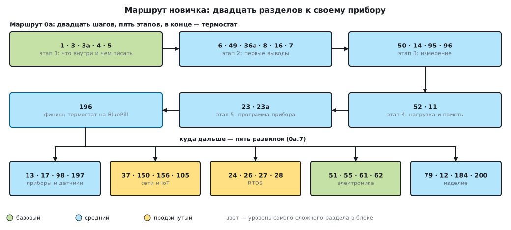
How this route differs from route A (0.3). Route A follows the blocks of the microcontroller and ends with FreeRTOS queues — twenty-one steps. Here twelve sections are the same, but eight others cover electronics, sensors and the device program: Ohm's law, the multimeter, the divider, connecting sensors, the thermistor, the relay driver, state machines instead of an OS — and the thermostat itself. The route ends not with an OS kernel but with a device.
0а.2 Stage 1: what is inside and what to write it with
Steps 1–5 are mostly reading; the board is needed once, at step 4. The goal of the stage is to understand what a register is and to be able to build and flash an empty project.
| Step | Section | What to take away | What to skip for now |
|---|---|---|---|
| 1 | 1 "The microcontroller as such" | core, memory, peripherals; a register is an address in the memory map (1.4) | bit-banding (1.5), the pipeline (1.7), the domestic Cortex-M3 (1.9) |
| 2 | 3 "C for embedded systems" | types from stdint.h (3.1), a pointer to a register (3.3) and volatile (3.4): without them the thermostat code cannot be read |
integer promotion (3.5), naming style (3.7) |
| 3 | 3а "Bit operations" | the four operations on a bit (3а.1), a field of several bits (3а.2), read-modify-write of a register (3а.6) | C bit fields (3а.7), byte order (3а.8) |
| 4 | 4 "Toolchain" | pick one IDE (4.2), set up the ST-Link (4.5), understand how firmware gets into the board (4.9) | CubeMX (4.7) and building without an IDE (4.8) |
| 5 | 5 "Three levels of abstraction: CMSIS, HAL and LL" | the route works with registers through the CMSIS headers, as the thermostat platform does (196.5); writing a register and adding bits to it are different things (5.4) | what each level turns into (5.5), a CubeMX project (5.7) |
One IDE, any of those in 4.2. Keil is covered in more detail in 4а, CubeIDE in 4б; both sections are references for their own IDE, and the route can be completed without them.
0а.3 Stage 2: the first pins
Steps 6–11 — the board is already on the desk. The goal of the stage is an LED, a button and a console: the device starts to respond.
| Step | Section | What to take away | What to skip for now |
|---|---|---|---|
| 6 | 6 "Clocking (RCC)" | the clock tree (6.2) and the main rule: a peripheral's clock is enabled by hand (6.5) | 72 MHz by hand (6.3): the internal 8 MHz HSI is enough for the thermostat (196.5); F4 (6.6), F0 and G0 (6.7), HSI trimming (6.8) |
| 7 | 49 "Voltage, current, power: Ohm's law and first calculations" | Ohm's law and power (49.2), the resistor for an LED (49.3), what a microcontroller pin can do (49.7) | markings (49.5) and package by power (49.6) |
| 8 | 36а "Instruments on the desk: multimeter, oscilloscope, logic analyzer" | the multimeter (36а.1) and a current-limited supply (36а.8) — the first two instruments on the desk | the oscilloscope and the logic analyzer (36а.2–36а.7) |
| 9 | 8 "Input/output ports (GPIO)" | pin modes and registers (8.2), the LED (8.4), the button (8.5) | HAL and CubeMX (8.3), F0 and G0 (8.6), the same pin on the 1986VE9x (8.7) |
| 10 | 16 "UART / USART" | baud rate calculation (16.2), transmit (16.3), receive (16.4), signal levels (16.7): the console is the main debugging tool and the thermostat's interface | variable-length packets (16.5), Modbus (16.8), USART on F0 and G0 (16.9) |
| 11 | 7 "Interrupts and exceptions" | SysTick (7.4) — the clock of the whole device; a button on an interrupt (7.6); what a handler should be like (7.7) | Cortex-M0 and M0+ (7.8); sections 7а–7в |
0а.4 Stage 3: measurement
Steps 12–15. The goal of the stage is a number on the console that changes when you squeeze the thermistor between your fingers.
| Step | Section | What to take away | What to skip for now |
|---|---|---|---|
| 12 | 50 "I–V curves, voltage dividers, RC circuits" | the divider (50.2) — the thermistor sits in one; the capacitor in front of the ADC (50.6); contact bounce (50.7) | the RC circuit in frequency (50.4), PWM plus RC instead of a DAC (50.5) |
| 13 | 14 "Analog-to-digital converter (ADC)" | conversion time (14.2), calibration on F1 (14.3), a single measurement (14.4) — exactly what the thermostat does | the channel sequence and DMA (14.5, 14.6), the analog watchdog (14.8), F0 and G0 (14.10) |
| 14 | 95 "How to connect sensors: power, pull-ups, levels, wires" | 3.3 or 5 volt supply (95.2), analog sensors (95.7), decoupling and ground (95.8) | I²C pull-ups, wire length, level shifters (95.3–95.6) — until the first sensor on a bus |
| 15 | 96 "Temperature: NTC thermistor and DS18B20" | the thermistor in a divider (96.2), code → degrees in integers (96.3) — the thermostat's sensor | DS18B20 (96.4–96.7) |
0а.5 Stages 4 and 5: load, memory, the whole device
Steps 16–20. The goal is a device that switches the heater on by itself, remembers the setpoint after power-off and does not hang while waiting.
| Step | Section | What to take away | What to skip for now |
|---|---|---|---|
| 16 | 52 "Driving loads: switches, relays, MOSFETs, drivers" | three ways and their cost (52.1), when a relay is appropriate (52.6): the thermostat switches the relay through a transistor | the gate and its circuitry (52.2–52.4), the high-side switch (52.5) |
| 17 | 11 "Memory, linking, boot" | where things live (11.1), stack and heap (11.4), writing to Flash (11.5) — this is how the thermostat remembers the setpoint | the linker script (11.3), option bytes (11.6), the record log (11.8) — it is on the list of improvements (196.6) |
| 18 | 23 "Why an operating system" | the limits of the superloop (23.1) and when an OS is not needed (23.6) | how an OS works and what it costs (23.2–23.5) |
| 19 | 23а "A device without an OS: state machines, event queue, non-blocking drivers" | a state machine: the transition table first (23а.1), a ring queue (23а.3), software timers on one tick (23а.4) | a non-blocking I²C driver (23а.5), sleeping between events (23а.6) |
| 20 | 196 "Mini-project: a thermostat on the BluePill" | logic separate from hardware (196.2), a run against a room model (196.4), register-level firmware (196.5) | nothing to skip; the improvements (196.6) come after the route |
The finish of the route is small: the thermostat firmware takes 1968 bytes of Flash and 64 bytes of RAM (196.5). Its logic is three states and the transitions between them (196.2), a main loop without an OS, time from SysTick. All of this is steps 11, 18 and 19 put together.
0а.6 Trouble spots on the route
Places where work gets stuck. The symptoms are taken word for word from the "Pitfalls" subsections of those very sections. If your symptom is not here, go to section 36: first the five questions in order (36.1), then the tables by symptom (36.2–36.11).
| Step | Symptom from "Pitfalls" | What is behind it | Where |
|---|---|---|---|
| 4 | The board has "died": the debugger will not connect. | the program has taken over the debug pins or went to sleep at once; BOOT0 = 1 and a reset start the bootloader |
4.11, 4.9 |
| 6 | A forgotten peripheral clock. | writes to the registers of a block without a clock silently go nowhere; check the register in the debugger, not the code | 6.9, 36.1 |
| 9 | The BluePill LED is inverted. | the LED is wired with its cathode to PC13: resetting the pin lights it, setting it turns it off |
8.9, 8.4 |
| 10 | Garbage instead of text. | the baud rates do not match or the divider was calculated for the wrong bus | 16.10, 16.2 |
| 10 | Nothing works, the lines are swapped. | TX of one side goes to RX of the other |
16.10 |
| 11 | Bounce turns into a dozen interrupts. | the button contact produces a burst of pulses; cured with a delay or an RC network | 7.9, 50.7 |
| 13 | The pin is not switched to analog mode. | the pin's digital circuitry stays connected and distorts the measurement | 14.11 |
| 13 | Forgotten calibration on F1. | the error is noticeably higher than expected | 14.11, 14.3 |
| 14 | A sensor's 5 V analog output goes straight into the ADC input. | more than 3.3 V on an ADC input is not allowed; a divider is needed | 95.9, 50.2 |
| 14 | No common ground. | the levels mean nothing, the sensor "answers with garbage" | 95.9 |
| 15 | The thermistor shows −40 or +125 and does not change. | the code has run off the edge of the table: an open or a short is a fault, not a temperature | 96.8, 196.1 |
| 16 | The microcontroller resets when the load switches. | a spike from the coil, a ground shared with the power circuit — route power and logic separately | 52.8, 49.8 |
| 17 | Writing to Flash on F1 raises PGERR. |
the cell written was not erased: the page is erased first | 11.10, 11.5 |
| 19 | "Wait 30 ms" inside a state machine action. | waiting inside an action stops the whole device; it is expressed as a state and a timer | 23а.8, 23а.5 |
0а.7 Where next: five forks
The thermostat is built — from here the road divides. Each fork is four sections in order; choose by what you want to make next.
Devices and sensors — the second and third device: - 13 "Timers (TIM)" — PWM, input capture and the encoder: time and frequency in hardware; - 17 "The I²C bus" — the bus of digital sensors; - 98 "Pressure and altitude: BMP280 and BME280" — the first sensor on a bus after the thermistor; - 197 "Mini-project: a frequency counter on a timer" — the second finished device.
Networks and IoT — a device you can see from afar: - 37 "IoT applications" — the whole picture; - 150 "ESP32 as a platform: chip, module, memory, pins, boot" — a second microcontroller, with a radio on the die; - 156 "Networking on the ESP32: esp_netif and lwIP, DHCP, SNTP, syslog, HTTP REST, MQTT" — the device on a network; - 105 "Networking from the bottom up: Ethernet, MAC, IP, subnets, ARP" — how a network works; then route G (0.6).
RTOS — when the superloop has become hard to read (23а.7): - 24 "Inside FreeRTOS" — what the kernel is made of; - 26 "Tasks" — a task and its stack; - 27 "Queues" — the main channel between tasks; - 28 "Interrupts in an RTOS" — the handler and the kernel; this is already the advanced level.
Electronics — the circuit around the device: - 51 "Semiconductors: diodes, Zener diodes, bipolar transistors" — what sits in the relay driver; - 55 "Linear regulators" — where the 3.3 volts come from; - 61 "Minimal microcontroller circuit: conditions for start-up" — what the chip needs without a ready-made board; - 62 "Pin protection" — so that a pin survives a wire; then route V (0.5).
Product — from a prototype to a device you are not ashamed to hand over: - 79 "How a device is born: development stages" — the whole path; - 12 "Service blocks: watchdogs, CRC, RTC" — the watchdog: the first improvement to the thermostat (196.6); - 184 "Firmware testing: levels, coverage, mutations, sanitizers" — a development of the technique from 196.2: the module is tested without a board; - 200 "First power-up of a new board" — when the prototype becomes a board.
0а.8 Pitfalls
Reading the route's sections in full. The column "What to skip for now" is half of the route. A section read from the first line to the last on the first pass slows you down more than a skipped subsection (0а.1).
Going past step five without a board. From step six on, text without hardware does not stick; the stage project is not an appendix to the reading but its test (0а.1).
Skipping the electronics. Steps 7, 8, 12, 14 and 16 are not a digression from programming: without a divider there is no sensor, without a switch there is no load, without a multimeter you cannot see which of these is not working (0а.3–0а.5).
Taking an OS before the device. The thermostat works without an RTOS: a main loop and SysTick (196.2). An RTOS is a fork after the route, not a step before the device (0а.7).
Looking for your symptom with a search across sections. First the table of trouble spots (0а.6), then the five questions of 36.1 — they are shorter than any search.
0а.9 Summary
- The route is twenty steps in five stages: what is inside and what to write it with (1–5), the first pins (6–11), measurement (12–15), load and memory (16–17), the device program and the device itself (18–20).
- The finish is the thermostat of 196: 1968 bytes of Flash, 64 bytes of RAM, no OS.
- It shares twelve sections with route A (0.3); eight others are electronics, sensors and the device program.
- No step is above the intermediate level; the first five steps are reading, after that only with the stage project on the desk.
- The table in 0а.6 has fourteen trouble spots, each taken word for word from the "Pitfalls" of its section; everything else is in section 36.
- After the route come five forks of four sections each: devices and sensors, networks and IoT, RTOS, electronics, product.
Next: section 0б "Topic routes: CAN and automotive diagnostics" — for those who already have a task: the sections of one topic in order. If there is no task yet, go straight to section 1 "The microcontroller as such".