 Embedded HandbookApps
103е. CCS811 and ENS160 air quality sensors over I2C: eCO₂ and TVOC, modes, warm-up and baseline, temperature and humidity compensation
In 103г and 103д carbon dioxide was measured with light: an NDIR sensor counts CO₂ molecules. The CCS811 and ENS160 work differently — inside there is a heated metal-oxide layer, like the MQ in 103.5, and a small processor that heats the layer itself, computes and returns ready numbers over I2C: TVOC — the sum of volatile organics in ppb — and eCO₂ in ppm. The "e" is the key: eCO₂ is not measured, it is derived from the organics. Here — what that means in practice; how to start the CCS811 (nWAKE, APP_START, HW_ID, mode) and the ENS160 (OPMODE, PART_ID); how to read the result by readiness or by nINT and what to do about clock stretching; why the sensor needs temperature and humidity and in what byte order to write them; why the first minutes and the first days are not trusted; how to save the baseline to Flash once a day and restore it after power-on.
Sources: RM0008 (DocID13902 Rev 17): a slave holds SCL — the master's high-level
counter stops until the line is released, p. 758; reception of one and two bytes
by the master, p. 764; more than two — method 2, pp. 762–763; a 1 KB Flash page
in medium-density devices, table 5, p. 54. DocID13587 Rev 17 (STM32F103x8/xB):
PB6 — I2C1_SCL, PB7 — I2C1_SDA, both FT, PB5 — not FT, p. 32; PB8 — FT,
p. 33; Flash endurance — 10 thousand cycles, table 29, p. 58. The I2C bus is
section 17, I2C1 setup at 100 kHz is 103г.2, writing to Flash is 11.5; they are
not repeated here. There are no ams or ScioSense documents in the project. The
register map of both chips, HW_ID 0x81, the STATUS and ERROR_ID bits, APP_START
0xF4, the mode codes, the 20 ms, 1 ms, 50 and 20 µs timings, the layout of
ALG_RESULT_DATA and ENV_DATA, PART_ID 0x0160, OPMODE, the DEVICE_STATUS fields,
TEMP_IN and RH_IN, the addresses 0x5A, 0x5B and 0x53 are taken from the ccs811
and ens160 drivers of Zephyr 4.4.2 on disk, and the output of its ccs811 sample
from the same place. The 20 min warm-up and 48 h run-in of the CCS811, the ENS160
address 0x52, the AQI levels 1–5 and the purpose of DATA_MISR are per the
manufacturer's documentation, not verified. All numbers are a run of the driver
_verify/voc103g/aq103g.c on a PC (gcc 12.2.0) with our own model of both chips
as I2C slaves in Python 3.11; the firmware was built with armclang 6.24 for
Cortex-M3. The layer physics, the algorithm inside the chip, the warm-up,
ageing, clock stretching and the ENS160 validity timings are assumptions in the
model: the numbers below describe the model, not the sensors.
What it is called in the documentation
Original Meaning MOX (metal oxide) gas sensor metal-oxide gas sensor TVOC (total volatile organic compounds) total volatile organic compounds (VOC), ppb eCO₂ (equivalent CO₂) computed CO₂ equivalent, ppm drive mode (MEAS_MODE) CCS811 measurement mode and period boot / application firmware (APP_START) boot loader / application firmware inside the sensor WAKEn / INTn pins "allow communication" input / "new measurement" output ENV_DATA, TEMP_IN / RH_IN temperature and humidity for compensation BASELINE register baseline register: what the chip takes for clean air OPMODE: deep sleep / idle / standard ENS160 mode: deep sleep / idle / operation VALIDITY_FLAG: initial start-up validity flag: initial start-up AQI-UBA air quality index on the UBA scale, 1–5 DATA_MISR check value of the data read from the ENS160
103е.1 What they measure and why eCO₂ is not CO₂
A metal-oxide layer heated to hundreds of degrees conducts better the more reducing gases are around — alcohol, acetone, products of breathing and cooking (per the manufacturer's documentation, not verified). The chip measures the conductance G and compares it with the baseline Gb — the conductance in the cleanest air it has seen. The ratio G / Gb gives TVOC, and TVOC gives eCO₂. The layer does not see carbon dioxide at all: Zephyr states plainly that the CCS811 estimates CO₂ where the main source of organics is people. Hence the rule: eCO₂ resembles CO₂ only while VOC and CO₂ come from one source — breathing.
In the model the layer conductance is G = G0 · (1 + VOC / 100 ppb)^0.7, and the chip computes TVOC = 100 · ((G / Gb)^(1/0.7) − 1) and eCO₂ = 400 + 4 · TVOC for the CCS811 and 400 + 3.5 · TVOC for the ENS160 (model assumptions: the real algorithm is not disclosed). People in the model add 0.25 ppb of organics for each ppm of CO₂ above 420. Next to them is the NDIR sensor from 103г: the true CO₂ plus 10 ppm noise, as in the SCD41 model. The sensors worked two hours in clean air, then:
| Scene | Real CO₂ | NDIR | eCO₂ CCS811 | eCO₂ ENS160 | TVOC CCS811 / real, ppb |
|---|---|---|---|---|---|
| two people in a closed room, after 2 h | 1285 | 1280 | 1262 | 1154 | 215 / 216 |
| table wiped with alcohol, after 5 min | 600 | 589 | 9840 | 8538 | 2360 / 2336 |
| CO₂ from a cylinder in a greenhouse, after 1 h | 1200 | 1197 | 402 | 406 | 1 / 0 |
| fresh air | 420 | 417 | 402 | 406 | 1 / 0 |
With people eCO₂ almost matched CO₂ — because the model tied breathing and organics together. Alcohol gave almost 10000 "ppm CO₂" against a real 600, and the CO₂ cylinder in the greenhouse is not seen at all: 402 against 1200. For ventilation by occupancy eCO₂ is a rough hint; for a greenhouse, a cellar, an incubator and anything where CO₂ comes without organics, NDIR is needed. TVOC is honest: 215 against 216, 2360 against 2336. That is what is worth showing, and eCO₂ should be labelled as an estimate.
| CCS811 | ENS160 | |
|---|---|---|
| address | 0x5A, second — 0x5B | 0x53, second — 0x52 (per documentation) |
| identify the chip | HW_ID (0x20) = 0x81 | PART_ID (0x00) = 0x0160, low byte first |
| start | APP_START — write byte 0xF4 | OPMODE (0x10) = 0x02 |
| modes | MEAS_MODE: 0 — off, 1 s, 10 s, 60 s, 250 ms | deep sleep, idle, operation |
| result | 8 bytes from 0x02: eCO₂, TVOC high byte first, STATUS, ERROR_ID, RAW | from 0x20: status, AQI, TVOC, eCO₂ — low byte first |
| "new data" | STATUS, bit 3 | status, bit 1 (NEWDAT) |
| other pins | nWAKE (input), nINT (output) | INT (output) |
| compensation | ENV_DATA (0x05): one byte each, step 0.5 | TEMP_IN = 64 · K, RH_IN = 512 · %RH |
| warm-up | no flag: 20 min per documentation | validity field 0–3 |
| baseline | BASELINE register (0x11) | no such register in the Zephyr map |
| errors | STATUS bit 0, cause in ERROR_ID | bit 6 (STATER) |
Connection to the F103 is one I2C1 bus at 100 kHz, as in 103г.2. Module supply and pull-ups are per their board; here — 3.3 V:
| Module pin | STM32F103 | Purpose |
|---|---|---|
| SCL (both) | PB6 | I2C1_SCL, FT |
| SDA (both) | PB7 | I2C1_SDA, FT |
| nWAKE (CCS811) | PB5 | output: zero — may talk |
| nINT (CCS811) | PB8 | input with pull-up, EXTI8 on the falling edge, FT |
| VCC, GND | 3.3 V, GND | supply |
PB5 is not FT (p. 32), but it is only an output. The temperature and humidity sensor for compensation — the SHT31 or AHT20 from section 97 — sits on the same bus.
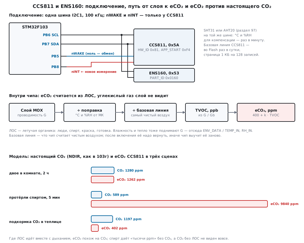
103е.2 CCS811: nWAKE, APP_START, HW_ID and mode
nWAKE. The input is active low: while it is one, the sensor does not answer
on I2C (that is how the pin is described in the Zephyr binding). Before each
exchange — zero and 50 µs, after — one and 20 µs (t_WAKE and t_DWAKE in the
Zephyr driver). If there is nothing to save, nWAKE is tied to ground and the
driver ignores it — the has_wake field = 0:
/* ── CCS811: каждый обмен — между nWAKE = 0 и nWAKE = 1, если вывод подключён ── */
static int ccs_rd(const aq_t *d, uint8_t reg, uint8_t *p, uint32_t n)
{
    int rc;
    if (d->has_wake) {
        aq_port_wake(1);
        aq_port_delay_us(CCS_US_WAKE);
    }
    rc = aq_port_read(d->addr, reg, p, n);
    if (d->has_wake) {
        aq_port_wake(0);
        aq_port_delay_us(CCS_US_DWAKE);
    }
    return rc;
}
In the model nWAKE left floating (has_wake = 0 and the pin not grounded) gives
−1, AQ_E_NACK, on the very first read. The same sensor with nWAKE grounded
starts with code 0.
Boot loader and application firmware. After power-on the CCS811 sits in its boot loader. STATUS bit 4 (APP_VALID) says the application firmware is present, bit 7 (FW_MODE) — that it is running. It is started by writing one byte 0xF4 — the address of the APP_START register without data — and waiting 1 ms. Before that, 20 ms after power-on (t_START) — the firmware waits them out. Then HW_ID, which must be 0x81, the version, the mode and a check that the mode was accepted:
/* запуск: STATUS → APP_START (0xF4) → STATUS → HW_ID = 0x81 → версия → MEAS_MODE → STATUS без ошибки */
int ccs_init(aq_t *d, uint8_t addr, uint8_t mode, uint8_t has_wake, uint8_t burnin, uint32_t now)
{
    uint8_t st, b[2], cmd = CCS_APP_START;
    int rc;
    *d = (aq_t){0};
    d->chip = AQ_CCS811;
    d->addr = addr;
    d->mode = mode;
    d->has_wake = has_wake;
    d->burnin = burnin;
    d->check_ready = 1;
    d->on_ms = now;
    if ((rc = ccs_rd(d, CCS_STATUS, &st, 1)) != AQ_OK)
        return rc;
    if (!(st & CCS_ST_APP_VALID))
        return AQ_E_APP;                                    /* в датчике нет прикладной прошивки */
    if (!(st & CCS_ST_FW_MODE)) {
        if ((rc = ccs_wr(d, &cmd, 1)) != AQ_OK)             /* APP_START — один байт, без данных */
            return rc;
        aq_port_delay_us(CCS_US_APP_START);
        if ((rc = ccs_rd(d, CCS_STATUS, &st, 1)) != AQ_OK)
            return rc;
        if (!(st & CCS_ST_FW_MODE))
            return AQ_E_APP;
    }
    if ((rc = ccs_rd(d, CCS_HW_ID, b, 1)) != AQ_OK)
        return rc;
    if (b[0] != CCS_HW_ID_VAL)
        return AQ_E_ID;
    if ((rc = ccs_rd(d, CCS_FW_APP_VER, b, 2)) != AQ_OK)
        return rc;
    d->app_ver = b[0];
    b[0] = CCS_MEAS_MODE;
    b[1] = mode;
    if ((rc = ccs_wr(d, b, 2)) != AQ_OK)
        return rc;
    if ((rc = ccs_rd(d, CCS_STATUS, &st, 1)) != AQ_OK)
        return rc;
    if (st & CCS_ST_ERROR) {
        (void)ccs_rd(d, CCS_ERROR_ID, b, 1);                /* чтение ERROR_ID снимает ошибку */
        return AQ_E_CHIP;
    }
    return AQ_OK;
}
In the model the start takes 7 exchanges and 4070 µs after those 20 ms; nWAKE toggles 14 times:
| Exchange | What the sensor returned |
|---|---|
| read STATUS | 0x10 — firmware present, not started |
write F4 |
— |
| read STATUS | 0x90 — application firmware running |
| read HW_ID | 0x81 |
| read FW_APP_VERSION | 20 00 (in the model — version 2.0) |
write 01 10 |
mode 1, once a second |
| read STATUS | 0x90 — no error |
A wrong mode — for example 0x50 — is not accepted: the error bit in STATUS and
MEASMODE_INVALID (bit 2) in ERROR_ID. The driver reads ERROR_ID, the read clears
the error (as in Zephyr), and returns −6, AQ_E_CHIP. A wrong address — 0x5B
instead of 0x5A — gives −1 on the first exchange.
Modes. MEAS_MODE, bits 6:4: 0 — do not measure, 1 — every 1 s, 2 — every 10 s, 3 — every 60 s, 4 — every 250 ms; bit 3 enables nINT. In Zephyr code 0x40 has two names — the 250 ms mode and RAW_DATA: per the manufacturer's documentation mode 4 has raw data only (not verified). On the fly Zephyr changes only the interrupt bits: the driver says that changing the mode of a running sensor has preconditions; which ones is per the manufacturer's documentation, not verified here. So the firmware sets the mode once at start.
103е.3 CCS811: result, readiness, nINT and clock stretching
ALG_RESULT_DATA is 8 bytes from register 0x02: eCO₂ and TVOC high byte first, STATUS, ERROR_ID and two RAW bytes. STATUS bit 3 (DATA_READY) says whether the registers hold a new measurement; reading clears it:
/* результат: 8 байт ALG_RESULT_DATA; eCO2 и TVOC — старшим байтом вперёд, байт 4 — STATUS, байт 5 — ERROR_ID */
int ccs_read(aq_t *d, aq_meas_t *m, uint32_t now)
{
    uint8_t b[8];
    uint32_t up = now - d->on_ms;
    int rc = ccs_rd(d, CCS_ALG_RESULT, b, 8);
    if (rc != AQ_OK) {
        d->n_err++;
        return rc;
    }
    m->eco2 = (uint16_t)(b[0] << 8 | b[1]);
    m->tvoc = (uint16_t)(b[2] << 8 | b[3]);
    m->status = b[4];
    m->error = b[5];
    m->raw = (uint16_t)(b[6] << 8 | b[7]);
    m->aqi = 0;
    if (m->status & CCS_ST_ERROR) {
        d->n_err++;
        return AQ_E_CHIP;
    }
    if (d->check_ready && !(m->status & CCS_ST_DATA_READY)) {
        d->n_stale++;                                       /* нового измерения нет: числа — прошлые */
        return AQ_E_STALE;
    }
    m->validity = (d->burnin && up < CCS_BURNIN_MS) ? 2u : (up < CCS_WARM_MS ? 1u : 0u);
    m->valid = m->validity == 0u;
    d->n_read++;
    return AQ_OK;
}
RAW is what the chip measures on the layer: the low 10 bits are the voltage,
1650000 / 1023 = 1612 µV per unit, the high 6 bits are the current in µA. In
the Zephyr sample after start — 0.677040 V and 14 µA; that is code 420: 420 ·
1612 = 677040 µV, and ccs_raw_uv gives exactly that. The same sample shows how
the sensor starts: the first two reads are 65021 ppm and 65021 ppb, then "no
new data", and from the fifth second — 400 ppm and 0 ppb. The first numbers
after start must not be used.
How many measurements. In the model the sensor clock is 0.3 % slow (model assumption). In 10 minutes:
| Mode | 1 (1 s) | 2 (10 s) | 3 (60 s) | 4 (250 ms) | 0 |
|---|---|---|---|---|---|
| measurements | 598 | 59 | 9 | 2392 | 0 |
In mode 0 a read returns −5, AQ_E_STALE: no data is ready.
Polling versus readiness. An hour of polling once a second:
| Mode | DATA_READY checked | Measurements | Accepted | "No new data" | Accepted again |
|---|---|---|---|---|---|
| 2 (10 s) | yes | 359 | 360 | 3240 | 0 |
| 2 (10 s) | no | 359 | 3600 | 0 | 3240 |
| 1 (1 s) | yes | 3594 | 3594 | 6 | 0 |
Without the DATA_READY check, in the 10 s mode the driver takes the previous measurement for a new one nine times out of ten — 3240 repeats per hour. An average over such numbers is an average over the same ones. 360 accepted with 359 measurements is not an error: the first read took a measurement made before the hour started. Even in the 1 s mode, polling once a second found the registers empty six times: the clocks of the sensor and the microcontroller differ.
nINT. With bit 3 in MEAS_MODE, nINT falls when a new measurement is ready and stays low until the result is read (as in the Zephyr binding). The firmware catches the falling edge on PB8 and reads in the main loop:
void EXTI9_5_IRQHandler(void)
{
    EXTI->PR = EXTI_PR_PR8;                                 /* снимается записью единицы */
    nint_flag = 1;                                          /* читать — в главном цикле */
}
In the model an hour in the 1 s mode gives 3589 measurements, 3589 reads, not one
empty, and the step follows the sensor clock: 1003 ms. If an edge is missed, the
line simply stays low, and the main loop reads by the GPIOB->IDR level.
Clock stretching. The CCS811 likes to hold SCL low while it prepares the reply. In the model this always happens when the result is read: in 90 % of cases for 20–100 µs, in 10 % — for 0.5–1.5 ms (model assumption: how long a real sensor holds it is not verified without a document). The F103 hardware I2C understands stretching: the master sees SCL low after its own rising edge and stops counting the high level until the line is released (p. 758). The trouble is the timeouts when waiting for flags. 10000 reads in mode 4:
| Port timeout | 0.2 ms | 0.5 ms | 1 ms | 2 ms | 25 ms |
|---|---|---|---|---|---|
| gave up | 981 | 982 | 506 | 0 | 0 |
The firmware uses 25 ms: more than ten times longer than any stretch in the model, and a broken wire is still caught.
/* ждать флаг; ведомый держит SCL — блок ждёт сам (RM0008, с. 758), а тайм-аут ловит обрыв и залипание */
static int sr1_wait(uint16_t mask)
{
    uint32_t t0 = DWT->CYCCNT;
    while (!(I2C1->SR1 & mask)) {
        if (I2C1->SR1 & I2C_SR1_AF)
            return AQ_E_NACK;
        if (expired(t0, I2C_TIMEOUT_US))
            return AQ_E_TIMEOUT;
    }
    return AQ_OK;
}
Worse is a bit-banged software I2C that releases SCL and does not check whether the line actually went up. The master samples bits while the sensor still holds the clock and SDA is released — it reads ones, and the sensor's data then shifts. A bit-level model, 10000 eCO₂ reads:
| Software I2C | 100 kHz | 10 kHz |
|---|---|---|
| does not wait for SCL | 10000 wrong | 6537 wrong |
| waits until SCL is one | 0 | 0 |
Slowing the bus does not help: stretching lasts microseconds, not clock periods. What helps is hardware I2C with a sensible timeout, or a software one that waits for a one on the line after every release of SCL.
Reading one and two bytes on the F1 has its own sequences (p. 764): one byte — clear ACK before clearing ADDR and STOP right away; two — POS and ACK before the address, then BTF and STOP. The port handles all three cases:
    if (n == 1u) {
        I2C1->CR1 &= (uint16_t)~I2C_CR1_ACK;                /* один байт: NACK и STOP сразу после ADDR */
        (void)I2C1->SR2;
        I2C1->CR1 |= I2C_CR1_STOP;
        if ((rc = sr1_wait(I2C_SR1_RXNE)) != AQ_OK)
            return fail(rc);
        p[0] = (uint8_t)I2C1->DR;
        return AQ_OK;
    }
103е.4 ENS160: OPMODE, PART_ID, status and data
The ENS160 in the Zephyr driver has neither APP_START nor nWAKE: everything is
done by the OPMODE register (0x10). 0x00 — deep sleep, 0x01 — idle, 0x02 —
operation, 0xF0 — reset; after each change — 10 ms (as in Zephyr). PART_ID is
two bytes low first, 60 01 = 0x0160. The chip puts its firmware version into
GPR_READ4…6 after command 0x0E in the COMMAND register; Zephyr asks for it in
idle mode, and this driver does the same:
/* запуск: сброс → PART_ID = 0x0160 → IDLE → версия прошивки → STANDARD; прогрев не ждём, его видно по статусу */
int ens_init(aq_t *d, uint8_t addr, uint32_t *appver)
{
    uint8_t b[3];
    int rc;
    *d = (aq_t){0};
    d->chip = AQ_ENS160;
    d->addr = addr;
    d->check_ready = 1;
    if ((rc = ens_opmode(d, ENS_OP_RESET)) != AQ_OK)
        return rc;
    if ((rc = aq_port_read(addr, ENS_PART_ID, b, 2)) != AQ_OK)
        return rc;
    if ((uint16_t)(b[1] << 8 | b[0]) != ENS_PART_ID_VAL)    /* младшим байтом вперёд: 60 01 */
        return AQ_E_ID;
    if ((rc = ens_opmode(d, ENS_OP_IDLE)) != AQ_OK)
        return rc;
    if ((rc = ens_wr1(d, ENS_COMMAND, ENS_CMD_GET_APPVER)) != AQ_OK)
        return rc;
    aq_port_delay_us(ENS_US_BOOT);
    if ((rc = aq_port_read(addr, ENS_GPR_READ4, b, 3)) != AQ_OK)
        return rc;
    *appver = (uint32_t)b[2] << 16 | (uint32_t)b[1] << 8 | b[0];
    return ens_opmode(d, ENS_OP_STANDARD);
}
In the model the start takes 6 exchanges and 42230 µs, almost all of it four 10 ms pauses. The model firmware is 5.4.6 (model assumption).
Status and data. Register 0x20 (DEVICE_STATUS in Zephyr): bit 6 (STATER) — error, bits 3:2 — validity, bit 1 (NEWDAT) — new measurement. Validity: 0 — normal, 1 — warm-up, 2 — initial start-up, 3 — invalid. Right after the status come AQI (0x21, bits 2:0), TVOC (0x22) and eCO₂ (0x24), both low byte first — so one 6-byte read takes everything:
/* результат одним чтением с 0x20: статус, AQI, TVOC и eCO2 (оба младшим байтом вперёд) */
int ens_read(aq_t *d, aq_meas_t *m)
{
    uint8_t b[6];
    int rc = aq_port_read(d->addr, ENS_DEV_STATUS, b, 6);
    if (rc != AQ_OK) {
        d->n_err++;
        return rc;
    }
    m->status = b[0];
    m->aqi = (uint8_t)(b[1] & 0x07u);
    m->tvoc = (uint16_t)(b[3] << 8 | b[2]);
    m->eco2 = (uint16_t)(b[5] << 8 | b[4]);
    m->error = 0;
    m->raw = 0;
    m->validity = (uint8_t)((b[0] >> ENS_VALID_SHIFT) & 3u);
    m->valid = m->validity == 0u;
    if (b[0] & ENS_ST_STATER) {
        d->n_err++;
        return AQ_E_CHIP;
    }
    if (d->check_ready && !(b[0] & ENS_ST_NEWDAT)) {
        d->n_stale++;
        return AQ_E_STALE;
    }
    d->n_read++;
    return AQ_OK;
}
The driver does not throw a number away during warm-up, it marks it: valid =
0. The Zephyr driver is stricter — after switching to operation it reads the
status and, if validity is not zero, refuses to start (-EINVAL). In the model
right after start the status is 0x08: validity 2, initial start-up — so a
Zephyr-style start would fail both for a new sensor and after every power-on
while the warm-up lasts.
AQI is an index on the UBA scale, 1–5 per the manufacturer's documentation (not verified); in the model the levels are taken from TVOC: up to 65, 220, 660 and 2200 ppb (model assumption). In the 103е.1 scenes people gave AQI 2, alcohol — 5.
DATA_MISR. Register 0x38 exists in the Zephyr map, but the driver does not read it. Per the manufacturer's documentation it is a check value the chip computes over the data it returned, so that the microcontroller can verify the read (not verified). How exactly it is computed is not on disk, so the driver does not check it; protection against corruption is the NEWDAT check, validity and plausibility of the numbers.
103е.5 Temperature and humidity compensation
Humidity and heat also raise the layer conductance. The chip divides G by a correction for the °C and %RH it was told; if it was told nothing, it assumes 25 °C and 50 % (Zephyr writes the same when there is no data). In the model the correction is e^(0.012 · (RH − 50) + 0.02 · (T − 25)) (model assumption). Where to get T and RH — the sensor from section 97 (SHT31 or AHT20) next to the module: the firmware sends them to both chips once a minute.
CCS811, ENV_DATA. Four bytes: humidity, zero, temperature, zero. Zephyr explains why: the low part is a fraction of which the chip looks only at the top bit, that is the half; so the meaningful bytes are the first and the third, 0.5 % and 0.5 °C each. Temperature is offset by +25 °C, below −25 °C — zero:
/* ENV_DATA: влажность и температура по байту, шаг 0,5; температура со сдвигом +25 °C; младшие байты — нули */
void ccs_env_bytes(int32_t t100, int32_t rh100, uint8_t out[4])
{
    int32_t h = (rh100 * 2 + 50) / 100, t;
    if (h < 0)
        h = 0;
    if (h > 200)
        h = 200;
    if (t100 < -2500)
        t = 0;                                              /* ниже −25 °C — ноль */
    else
        t = ((t100 + 2500) * 2 + 50) / 100;
    if (t > 255)
        t = 255;
    out[0] = (uint8_t)h;
    out[1] = 0;
    out[2] = (uint8_t)t;
    out[3] = 0;
}
ENS160, TEMP_IN and RH_IN. Two words low byte first: 64 · kelvin and 512 · %RH. Zephyr accepts only −5…60 °C and 20…80 %, outside — an error; this driver clamps to the edge:
/* TEMP_IN = 64 · (°C + 273,15), RH_IN = 512 · %RH, к ближайшему; пределы −5…60 °C и 20…80 % — как в Zephyr */
void ens_env_words(int32_t t100, int32_t rh100, uint16_t *t_in, uint16_t *rh_in)
{
    if (t100 < -500)
        t100 = -500;
    if (t100 > 6000)
        t100 = 6000;
    if (rh100 < 2000)
        rh100 = 2000;
    if (rh100 > 8000)
        rh100 = 8000;
    *t_in = (uint16_t)((64 * (t100 + 27315) + 50) / 100);
    *rh_in = (uint16_t)((512 * rh100 + 50) / 100);
}
| °C, %RH | ENV_DATA CCS811 | TEMP_IN | RH_IN |
|---|---|---|---|
| 25, 50 | 64 00 64 00 |
19082 | 25600 |
| 22, 60 | 78 00 5E 00 |
18890 | 30720 |
| 22.4, 43.8 | 58 00 5F 00 |
18915 | 22426 |
| −26, 50 | 64 00 00 00 |
17162 (−5 °C) | 25600 |
| 60, 90 | B4 00 AA 00 |
21322 | 40960 (80 %) |
What compensation gives. Clean air, the sensors learned for 2 h at 25 °C and 50 %, then an hour under other conditions. TVOC at the end of the hour, ppb (really 0):
| An hour at | Without compensation, CCS811 / ENS160 | With compensation, CCS811 / ENS160 |
|---|---|---|
| 25 °C, 30 % | 1 / 1, and after returning to 50 % — 39 | 2 / 2, after returning — 0 |
| 25 °C, 50 % | 2 / 2 | 2 / 2 |
| 25 °C, 70 % | 43 / 42 | 2 / 2 |
| 25 °C, 85 % | 85 / 84 | 2 / 10 |
| 35 °C, 50 % | 35 / 35 | 2 / 2 |
Damp air without compensation gives up to 85 ppb of "organics" out of nothing. A dry hour is more insidious: TVOC does not rise, but the baseline slides down after the "clean" dry air, and after returning to 50 % it reads 39 ppb for another hour. The 10 ppb of the ENS160 at 85 % is the 80 % limit from Zephyr: compensation does not see the remaining 5 %.
Byte order. 22 °C and 60 %, the sensors learned the baseline with correct compensation, then 200 ppb of organics appeared and the sensor was written:
| What was written | Chip understood | TVOC, ppb | eCO₂, ppm |
|---|---|---|---|
| CCS811, correct | 22 °C, 60 % | 199 | 1198 |
| CCS811, temperature and humidity swapped | 35 °C, 47 % | 159 | 1034 |
| CCS811, meaningful bytes in place of the zeros | −25 °C, 0 % | 2875 | 11900 |
| ENS160, words high byte first | 536 °C, 0.2 % | 0 | — |
Swapped fields give a 20 % error. Bytes out of place turn 200 ppb into 2875. And the ENS160 with "high byte first" words got 536 °C and went blind: TVOC is zero at 200 ppb.
103е.6 Warm-up, run-in and the baseline in Flash
Warm-up. Per the manufacturer's documentation the CCS811 needs 20 minutes
after each power-on, and a new sensor 48 hours of operation, before its numbers
become right (not verified). The CCS811 has no warm-up flag — the driver keeps it
by time from power-on: in aq_meas_t the field validity = 1 for the first
20 min and 2 for the first 48 h of a new sensor, and valid = 0. In the model
the conductance after power-on is raised 1 + e^(−t / 240 s) times (model
assumption). Air — 100 ppb, the baseline restored right at power-on:
| After power-on | 1 min | 5 min | 10 min | 20 min | 30 min |
|---|---|---|---|---|---|
| TVOC, ppb | 359 | 187 | 124 | 101 | 101 |
valid |
0 | 0 | 0 | 1 | 1 |
That is why the firmware restores the baseline not at once but after 20 minutes.
The ENS160 shows its warm-up in the status. In the model — 3 minutes of warm-up after each power-on and an hour of initial start-up for a new sensor (model assumption):
| ENS160 | Validity by time from start |
|---|---|
| new | 2 (initial start-up) until 3600 s, then 0 |
| used | 1 (warm-up) until 180 s, then 0 |
Baseline. Gb is what the chip takes for clean air. In the model after a power-on without a hint it takes the surrounding air for clean, then follows cleaner air within 10 minutes and dirtier air within 7 days; the layer ages, and clean air gives 0.5 % more conductance per day; a new sensor has a conductance raised 1 + 0.6 · e^(−t / 10 h) times during its first hours (model assumptions). The CCS811 returns Gb in the BASELINE register — two bytes whose meaning the chip does not disclose: they are read, stored and written back as is (as in Zephyr). An office: 300 ppb from 9 to 18, aired at night; the sensor is 40 days old and was powered on at 14:00. TVOC / real, ppb:
| Baseline at power-on | After 30 min | After 2 h | Next day at noon |
|---|---|---|---|
| none, the chip learns anew | 0 / 300 | 1 / 300 | 285 / 300 |
| saved yesterday | 301 / 300 | 295 / 300 | 285 / 300 |
| saved a month ago | 383 / 300 | 373 / 300 | 327 / 300 |
| saved 2 h after the first power-on | 193 / 300 | 190 / 300 | 285 / 300 |
Without a baseline the sensor took 300 ppb for clean air and showed zero until the evening — the truth returned only after airing at night. Yesterday's baseline gave correct numbers after 20 minutes. A month-old one — +83 ppb, and still +27 the next day: the layer has aged, and the baseline creeps up over weeks. A baseline saved in the first hours of the sensor's life reads a third low. Hence the rule: save once a day, for a new sensor — not before 48 hours.
Journal in Flash. A record is 8 bytes: tag, baseline, number, check. A 1 KB
page (table 5, p. 54) holds 128 records; once a day — one erase per 128 days,
and 10 thousand erases (table 29, p. 58) last 3507 years. The tag is written
first: if power fails in the middle of a write, the slot is taken, and
bl_load skips the incomplete record. More on journals — in 11.8:
int bl_save(uint16_t bl, uint32_t *erases)
{
    uint16_t old = 0, s = 0;
    uint32_t off = 0;
    int rc;
    if (bl_load(&old, &s) == 0)
        s = 0;
    while (off < BL_PAGE && aq_port_flash_read16(off) != 0xFFFFu)
        off += BL_REC;
    if (off >= BL_PAGE) {                                   /* страница кончилась — стереть, раз в 128 записей */
        if ((rc = aq_port_flash_erase()) != AQ_OK)
            return rc;
        (*erases)++;
        off = 0;
    }
    s++;
    if ((rc = aq_port_flash_write16(off, BL_TAG)) != AQ_OK || (rc = aq_port_flash_write16(off + 2u, bl)) != AQ_OK
        || (rc = aq_port_flash_write16(off + 4u, s)) != AQ_OK)
        return rc;
    return aq_port_flash_write16(off + 6u, chk(bl, s));
}
On the stand — 400 days of saves: 3 erases, 1600 half-word writes, not one write
to an unerased cell, the last one is 0x8190 with number 400. A break after two
half-words: bl_save returned −7, bl_load still returned 0x8190 number 400,
and the next save went to the next slot.
In the firmware:
        if (have_bl && !restored && now - C.on_ms >= CCS_WARM_MS) {
            restored = ccs_set_baseline(&C, bl) == AQ_OK;   /* вернуть линию — после прогрева 20 мин */
        }
        if (now - t_save >= DAY_MS && !(C.burnin && now - C.on_ms < CCS_BURNIN_MS)) {
            t_save = now;
            if (ccs_get_baseline(&C, &bl) == AQ_OK && bl_save(bl, &er) == AQ_OK) {
                baseline = bl;                              /* раз в сутки: страница 1 КБ — на 128 суток */
                bl_erases = er;
                have_bl = 1;
            }
        }
The firmware treats an empty journal as a sign of a new sensor: burnin = 1,
and the baseline is not saved for the first 48 h. When the sensor is replaced,
the journal is erased. The ENS160 has no baseline register in the Zephyr map:
per the manufacturer's documentation it keeps the baseline itself (not
verified).
103е.7 Pitfalls
eCO₂ taken for CO₂. The layer does not see carbon dioxide. In the model alcohol gave 9840 ppm of "CO₂" at 600, and a CO₂ cylinder — 402 at 1200. Where real CO₂ matters — NDIR from 103г or 103д.
nWAKE left floating. While it is not zero, the CCS811 is silent: −1 on the very first exchange. Either an MCU pin and 50 µs before the exchange, or ground.
APP_START forgotten. After power-on the CCS811 is in the boot loader, STATUS = 0x10, no data. Write byte 0xF4, 1 ms, STATUS = 0x90.
Polling without DATA_READY or NEWDAT. The 10 s mode polled once a second — 3240 repeats of the previous measurement per hour. Check the ready bit or read by nINT.
Clock stretching. A flag timeout of 0.2 ms — 981 failures in 10000 reads, 1 ms — 506; 2 ms and more — zero. A software I2C that does not wait for SCL spoils every read at 100 kHz and 6537 of 10000 at 10 kHz.
Byte order of ENV_DATA and TEMP_IN. CCS811: humidity is the first byte, temperature the third, offset by +25 °C; ENS160: words low byte first. A wrong order gives 2875 ppb instead of 200 or a blind sensor.
The first minutes and the first days. The first CCS811 reads after start in the Zephyr sample are 65021. 20 minutes after power-on and 48 h for a new one — per documentation; in the model one minute after power-on reads 359 ppb at 100. For the ENS160 look at the validity field instead of refusing to start, as Zephyr does.
Baseline: not restored, restored early, an old one saved. Without restoring — zero until the evening at 300 ppb; a month-old baseline — +83 ppb; one saved in the first hours — −107. Save once a day, not before 48 h, restore after the 20 min warm-up.
103е.8 Summary
- The CCS811 and ENS160 are metal-oxide sensors of volatile organics: TVOC is measured, eCO₂ is computed from it. In the model alcohol gives 9840 ppm eCO₂ at 600 ppm CO₂, a CO₂ cylinder — 402 at 1200.
- CCS811: address 0x5A or 0x5B; nWAKE low for every exchange (50 and 20 µs); STATUS 0x10 → write 0xF4 → 0x90; HW_ID 0x81; the mode is MEAS_MODE, 1 s, 10 s, 60 s or 250 ms; the result is 8 bytes high first, readiness — STATUS bit 3 or nINT.
- ENS160: address 0x53 or 0x52; OPMODE 0xF0 → 0x01 → 0x02, 10 ms each; PART_ID
60 01; the result in one 6-byte read from 0x20, low byte first; validity — status bits 3:2. - Clock stretching: the F1 hardware I2C waits for it (p. 758); the flag timeout is at least 2 ms in the model, 25 ms in the firmware.
- Compensation: ENV_DATA is
humidity·2, 0, (T + 25)·2, 0; TEMP_IN = 64 · K, RH_IN = 512 · %RH low byte first; without it, 85 % gives 85 ppb out of nothing. - The CCS811 baseline goes to Flash once a day, not before 48 h for a new sensor, and is restored 20 min after power-on; 128 records per 1 KB page — an erase every 128 days.
Full sources
aq103g.h — registers and bits of both chips, timings, error codes, structures and driver functions.
/* aq103g.h — раздел 103е: драйвер датчиков качества воздуха CCS811 и ENS160 по I2C без регистров микроконтроллера.
 * Обмен — функции порта (aq_port_*): в прошивке fw103g.c это I2C1, вывод nWAKE и Flash STM32F103, в стенде
 * host103g.c — модель model103g.py.
 * Регистры, биты STATUS и ERROR_ID, коды MEAS_MODE, HW_ID 0x81, APP_START 0xF4, сроки t_START, t_APP_START, t_WAKE и
 * t_DWAKE, формат ENV_DATA, PART_ID 0x0160, OPMODE, поля DEVICE_STATUS, TEMP_IN = 64 · K и RH_IN = 512 · %RH младшим
 * байтом вперёд, 10 мс после смены OPMODE — как в драйверах ccs811 и ens160 Zephyr 4.4.2. Прогрев 20 мин и 48 ч
 * первого включения CCS811 — по документации производителя, с датчиком не сверено. */
#ifndef AQ103G_H
#define AQ103G_H
#include <stdint.h>

/* ── CCS811 ─────────────────────────────────────────────────────────────── */
#define CCS_ADDR          0x5Au         /* второй адрес — 0x5B */
#define CCS_STATUS        0x00u
#define CCS_MEAS_MODE     0x01u
#define CCS_ALG_RESULT    0x02u         /* 8 байт: eCO2, TVOC (старшим вперёд), STATUS, ERROR_ID, RAW */
#define CCS_ENV_DATA      0x05u         /* 4 байта: влажность, 0, температура, 0 */
#define CCS_BASELINE      0x11u
#define CCS_HW_ID         0x20u
#define CCS_FW_APP_VER    0x24u
#define CCS_ERROR_ID      0xE0u
#define CCS_APP_START     0xF4u
#define CCS_HW_ID_VAL     0x81u
#define CCS_ST_ERROR      0x01u
#define CCS_ST_DATA_READY 0x08u
#define CCS_ST_APP_VALID  0x10u
#define CCS_ST_FW_MODE    0x80u
#define CCS_MODE_IDLE     0x00u         /* режим 0 — не мерит */
#define CCS_MODE_1S       0x10u         /* режим 1 — раз в 1 с */
#define CCS_MODE_10S      0x20u         /* режим 2 — раз в 10 с */
#define CCS_MODE_60S      0x30u         /* режим 3 — раз в 60 с */
#define CCS_MODE_250MS    0x40u         /* режим 4 — раз в 250 мс */
#define CCS_MODE_INT_DRDY 0x08u         /* nINT — при новом измерении */
#define CCS_US_START      20000u        /* t_START после включения питания */
#define CCS_US_APP_START  1000u         /* t_APP_START */
#define CCS_US_WAKE       50u           /* t_WAKE: nWAKE в ноль — и только потом обмен */
#define CCS_US_DWAKE      20u           /* t_DWAKE: после обмена nWAKE в единицу */
#define CCS_WARM_MS       1200000u      /* 20 мин после каждого включения (по документации) */
#define CCS_BURNIN_MS     172800000u    /* 48 ч первого включения нового датчика (по документации) */

/* ── ENS160 ─────────────────────────────────────────────────────────────── */
#define ENS_ADDR          0x53u         /* второй адрес — 0x52 */
#define ENS_PART_ID       0x00u         /* 2 байта, младшим вперёд: 0x0160 */
#define ENS_OPMODE        0x10u
#define ENS_CONFIG        0x11u
#define ENS_COMMAND       0x12u
#define ENS_TEMP_IN       0x13u         /* 64 · K, младшим вперёд */
#define ENS_RH_IN         0x15u         /* 512 · %RH, младшим вперёд */
#define ENS_DEV_STATUS    0x20u         /* за ним подряд AQI (0x21), TVOC (0x22), eCO2 (0x24) */
#define ENS_DATA_MISR     0x38u
#define ENS_GPR_READ4     0x4Cu
#define ENS_PART_ID_VAL   0x0160u
#define ENS_OP_SLEEP      0x00u         /* глубокий сон */
#define ENS_OP_IDLE       0x01u
#define ENS_OP_STANDARD   0x02u
#define ENS_OP_RESET      0xF0u
#define ENS_CMD_GET_APPVER 0x0Eu
#define ENS_ST_STATER     0x40u         /* ошибка */
#define ENS_ST_NEWDAT     0x02u
#define ENS_VALID_SHIFT   2u            /* биты 3:2: 0 — норма, 1 — прогрев, 2 — начальный запуск, 3 — негодно */
#define ENS_US_BOOT       10000u        /* 10 мс после смены OPMODE */

enum { AQ_OK = 0, AQ_E_NACK = -1, AQ_E_TIMEOUT = -2, AQ_E_ID = -3, AQ_E_APP = -4, AQ_E_STALE = -5, AQ_E_CHIP = -6,
       AQ_E_ARG = -7 };
enum { AQ_CCS811 = 1, AQ_ENS160 = 2 };

typedef struct {
    uint16_t eco2, tvoc, raw;           /* eCO2 — ppm, TVOC — ppb */
    uint8_t status, error, aqi;         /* error — ERROR_ID CCS811; aqi — AQI-UBA ENS160 */
    uint8_t validity;                   /* ENS160: 0…3; CCS811: 0 — норма, 1 — прогрев, 2 — первые 48 ч */
    uint8_t valid;                      /* числу можно верить */
} aq_meas_t;

typedef struct {
    uint8_t chip, addr, mode, has_wake; /* has_wake: nWAKE подключён к выводу, а не к земле */
    uint8_t app_ver, check_ready;       /* check_ready: 1; 0 — не смотреть DATA_READY/NEWDAT (для опыта) */
    uint8_t burnin;                     /* 1 — датчик новый, ещё не отработал 48 ч */
    uint32_t on_ms;                     /* когда включилось питание датчика */
    uint32_t n_read, n_stale, n_err;
} aq_t;

/* ── порт: в прошивке — I2C1, PB5 (nWAKE) и Flash; в стенде — строки к модели ── */
int aq_port_write(uint8_t addr7, const uint8_t *p, uint32_t n);
int aq_port_read(uint8_t addr7, uint8_t reg, uint8_t *p, uint32_t n);   /* запись адреса регистра, повторный старт, чтение */
void aq_port_wake(uint8_t active);                                       /* 1 — nWAKE в ноль */
void aq_port_delay_us(uint32_t us);
int aq_port_flash_erase(void);
int aq_port_flash_write16(uint32_t off, uint16_t v);
uint16_t aq_port_flash_read16(uint32_t off);

/* ── CCS811 ── */
int ccs_init(aq_t *d, uint8_t addr, uint8_t mode, uint8_t has_wake, uint8_t burnin, uint32_t now);
int ccs_read(aq_t *d, aq_meas_t *m, uint32_t now);
int ccs_env(aq_t *d, int32_t t100, int32_t rh100);
void ccs_env_bytes(int32_t t100, int32_t rh100, uint8_t out[4]);
int ccs_get_baseline(aq_t *d, uint16_t *bl);
int ccs_set_baseline(aq_t *d, uint16_t bl);
uint32_t ccs_raw_uv(uint16_t raw);

/* ── ENS160 ── */
int ens_init(aq_t *d, uint8_t addr, uint32_t *appver);
int ens_read(aq_t *d, aq_meas_t *m);
int ens_env(aq_t *d, int32_t t100, int32_t rh100);
void ens_env_words(int32_t t100, int32_t rh100, uint16_t *t_in, uint16_t *rh_in);
int ens_opmode(aq_t *d, uint8_t op);

/* ── базовая линия CCS811 во Flash: запись 8 байт, страница 1 КБ — 128 записей ── */
#define BL_PAGE           1024u
#define BL_REC            8u
#define BL_TAG            0xB15Eu
int bl_load(uint16_t *bl, uint16_t *seq);
int bl_save(uint16_t bl, uint32_t *erases);

#endif
aq103g.c — the driver: starting the CCS811 and ENS160, reading the result with a readiness check, compensation, the baseline and its Flash journal.
/* aq103g.c — раздел 103е: драйвер CCS811 и ENS160. Запуск, чтение результата с проверкой готовности, компенсация
 * температуры и влажности, базовая линия CCS811 и её журнал во Flash. Регистров микроконтроллера здесь нет: тот же
 * файл собирается в прошивку и в стенд на компьютере. */
#include "aq103g.h"

/* ── CCS811: каждый обмен — между nWAKE = 0 и nWAKE = 1, если вывод подключён ── */
static int ccs_rd(const aq_t *d, uint8_t reg, uint8_t *p, uint32_t n)
{
    int rc;
    if (d->has_wake) {
        aq_port_wake(1);
        aq_port_delay_us(CCS_US_WAKE);
    }
    rc = aq_port_read(d->addr, reg, p, n);
    if (d->has_wake) {
        aq_port_wake(0);
        aq_port_delay_us(CCS_US_DWAKE);
    }
    return rc;
}

static int ccs_wr(const aq_t *d, const uint8_t *p, uint32_t n)
{
    int rc;
    if (d->has_wake) {
        aq_port_wake(1);
        aq_port_delay_us(CCS_US_WAKE);
    }
    rc = aq_port_write(d->addr, p, n);
    if (d->has_wake) {
        aq_port_wake(0);
        aq_port_delay_us(CCS_US_DWAKE);
    }
    return rc;
}

/* запуск: STATUS → APP_START (0xF4) → STATUS → HW_ID = 0x81 → версия → MEAS_MODE → STATUS без ошибки */
int ccs_init(aq_t *d, uint8_t addr, uint8_t mode, uint8_t has_wake, uint8_t burnin, uint32_t now)
{
    uint8_t st, b[2], cmd = CCS_APP_START;
    int rc;
    *d = (aq_t){0};
    d->chip = AQ_CCS811;
    d->addr = addr;
    d->mode = mode;
    d->has_wake = has_wake;
    d->burnin = burnin;
    d->check_ready = 1;
    d->on_ms = now;
    if ((rc = ccs_rd(d, CCS_STATUS, &st, 1)) != AQ_OK)
        return rc;
    if (!(st & CCS_ST_APP_VALID))
        return AQ_E_APP;                                    /* в датчике нет прикладной прошивки */
    if (!(st & CCS_ST_FW_MODE)) {
        if ((rc = ccs_wr(d, &cmd, 1)) != AQ_OK)             /* APP_START — один байт, без данных */
            return rc;
        aq_port_delay_us(CCS_US_APP_START);
        if ((rc = ccs_rd(d, CCS_STATUS, &st, 1)) != AQ_OK)
            return rc;
        if (!(st & CCS_ST_FW_MODE))
            return AQ_E_APP;
    }
    if ((rc = ccs_rd(d, CCS_HW_ID, b, 1)) != AQ_OK)
        return rc;
    if (b[0] != CCS_HW_ID_VAL)
        return AQ_E_ID;
    if ((rc = ccs_rd(d, CCS_FW_APP_VER, b, 2)) != AQ_OK)
        return rc;
    d->app_ver = b[0];
    b[0] = CCS_MEAS_MODE;
    b[1] = mode;
    if ((rc = ccs_wr(d, b, 2)) != AQ_OK)
        return rc;
    if ((rc = ccs_rd(d, CCS_STATUS, &st, 1)) != AQ_OK)
        return rc;
    if (st & CCS_ST_ERROR) {
        (void)ccs_rd(d, CCS_ERROR_ID, b, 1);                /* чтение ERROR_ID снимает ошибку */
        return AQ_E_CHIP;
    }
    return AQ_OK;
}

/* результат: 8 байт ALG_RESULT_DATA; eCO2 и TVOC — старшим байтом вперёд, байт 4 — STATUS, байт 5 — ERROR_ID */
int ccs_read(aq_t *d, aq_meas_t *m, uint32_t now)
{
    uint8_t b[8];
    uint32_t up = now - d->on_ms;
    int rc = ccs_rd(d, CCS_ALG_RESULT, b, 8);
    if (rc != AQ_OK) {
        d->n_err++;
        return rc;
    }
    m->eco2 = (uint16_t)(b[0] << 8 | b[1]);
    m->tvoc = (uint16_t)(b[2] << 8 | b[3]);
    m->status = b[4];
    m->error = b[5];
    m->raw = (uint16_t)(b[6] << 8 | b[7]);
    m->aqi = 0;
    if (m->status & CCS_ST_ERROR) {
        d->n_err++;
        return AQ_E_CHIP;
    }
    if (d->check_ready && !(m->status & CCS_ST_DATA_READY)) {
        d->n_stale++;                                       /* нового измерения нет: числа — прошлые */
        return AQ_E_STALE;
    }
    m->validity = (d->burnin && up < CCS_BURNIN_MS) ? 2u : (up < CCS_WARM_MS ? 1u : 0u);
    m->valid = m->validity == 0u;
    d->n_read++;
    return AQ_OK;
}

/* ENV_DATA: влажность и температура по байту, шаг 0,5; температура со сдвигом +25 °C; младшие байты — нули */
void ccs_env_bytes(int32_t t100, int32_t rh100, uint8_t out[4])
{
    int32_t h = (rh100 * 2 + 50) / 100, t;
    if (h < 0)
        h = 0;
    if (h > 200)
        h = 200;
    if (t100 < -2500)
        t = 0;                                              /* ниже −25 °C — ноль */
    else
        t = ((t100 + 2500) * 2 + 50) / 100;
    if (t > 255)
        t = 255;
    out[0] = (uint8_t)h;
    out[1] = 0;
    out[2] = (uint8_t)t;
    out[3] = 0;
}

int ccs_env(aq_t *d, int32_t t100, int32_t rh100)
{
    uint8_t b[5] = {CCS_ENV_DATA};
    ccs_env_bytes(t100, rh100, &b[1]);
    return ccs_wr(d, b, 5);
}

/* базовая линия — два байта как есть: что в них, датчик не раскрывает; сохранить и вернуть тем же порядком */
int ccs_get_baseline(aq_t *d, uint16_t *bl)
{
    uint8_t b[2];
    int rc = ccs_rd(d, CCS_BASELINE, b, 2);
    if (rc == AQ_OK)
        *bl = (uint16_t)(b[0] << 8 | b[1]);
    return rc;
}

int ccs_set_baseline(aq_t *d, uint16_t bl)
{
    uint8_t b[3] = {CCS_BASELINE, (uint8_t)(bl >> 8), (uint8_t)bl};
    return ccs_wr(d, b, 3);
}

/* напряжение на слое: младшие 10 бит RAW, 1 650 000 мкВ / 1023 = 1612 мкВ на единицу; ток — старшие 6 бит, мкА */
uint32_t ccs_raw_uv(uint16_t raw)
{
    return (uint32_t)(raw & 0x3FFu) * (1650000u / 1023u);
}

/* ── ENS160 ─────────────────────────────────────────────────────────────── */
static int ens_wr1(const aq_t *d, uint8_t reg, uint8_t v)
{
    uint8_t b[2] = {reg, v};
    return aq_port_write(d->addr, b, 2);
}

int ens_opmode(aq_t *d, uint8_t op)
{
    int rc = ens_wr1(d, ENS_OPMODE, op);
    aq_port_delay_us(ENS_US_BOOT);                          /* 10 мс после смены режима */
    return rc;
}

/* запуск: сброс → PART_ID = 0x0160 → IDLE → версия прошивки → STANDARD; прогрев не ждём, его видно по статусу */
int ens_init(aq_t *d, uint8_t addr, uint32_t *appver)
{
    uint8_t b[3];
    int rc;
    *d = (aq_t){0};
    d->chip = AQ_ENS160;
    d->addr = addr;
    d->check_ready = 1;
    if ((rc = ens_opmode(d, ENS_OP_RESET)) != AQ_OK)
        return rc;
    if ((rc = aq_port_read(addr, ENS_PART_ID, b, 2)) != AQ_OK)
        return rc;
    if ((uint16_t)(b[1] << 8 | b[0]) != ENS_PART_ID_VAL)    /* младшим байтом вперёд: 60 01 */
        return AQ_E_ID;
    if ((rc = ens_opmode(d, ENS_OP_IDLE)) != AQ_OK)
        return rc;
    if ((rc = ens_wr1(d, ENS_COMMAND, ENS_CMD_GET_APPVER)) != AQ_OK)
        return rc;
    aq_port_delay_us(ENS_US_BOOT);
    if ((rc = aq_port_read(addr, ENS_GPR_READ4, b, 3)) != AQ_OK)
        return rc;
    *appver = (uint32_t)b[2] << 16 | (uint32_t)b[1] << 8 | b[0];
    return ens_opmode(d, ENS_OP_STANDARD);
}

/* результат одним чтением с 0x20: статус, AQI, TVOC и eCO2 (оба младшим байтом вперёд) */
int ens_read(aq_t *d, aq_meas_t *m)
{
    uint8_t b[6];
    int rc = aq_port_read(d->addr, ENS_DEV_STATUS, b, 6);
    if (rc != AQ_OK) {
        d->n_err++;
        return rc;
    }
    m->status = b[0];
    m->aqi = (uint8_t)(b[1] & 0x07u);
    m->tvoc = (uint16_t)(b[3] << 8 | b[2]);
    m->eco2 = (uint16_t)(b[5] << 8 | b[4]);
    m->error = 0;
    m->raw = 0;
    m->validity = (uint8_t)((b[0] >> ENS_VALID_SHIFT) & 3u);
    m->valid = m->validity == 0u;
    if (b[0] & ENS_ST_STATER) {
        d->n_err++;
        return AQ_E_CHIP;
    }
    if (d->check_ready && !(b[0] & ENS_ST_NEWDAT)) {
        d->n_stale++;
        return AQ_E_STALE;
    }
    d->n_read++;
    return AQ_OK;
}

/* TEMP_IN = 64 · (°C + 273,15), RH_IN = 512 · %RH, к ближайшему; пределы −5…60 °C и 20…80 % — как в Zephyr */
void ens_env_words(int32_t t100, int32_t rh100, uint16_t *t_in, uint16_t *rh_in)
{
    if (t100 < -500)
        t100 = -500;
    if (t100 > 6000)
        t100 = 6000;
    if (rh100 < 2000)
        rh100 = 2000;
    if (rh100 > 8000)
        rh100 = 8000;
    *t_in = (uint16_t)((64 * (t100 + 27315) + 50) / 100);
    *rh_in = (uint16_t)((512 * rh100 + 50) / 100);
}

int ens_env(aq_t *d, int32_t t100, int32_t rh100)
{
    uint16_t t, h;
    uint8_t b[3];
    int rc;
    ens_env_words(t100, rh100, &t, &h);
    b[0] = ENS_TEMP_IN;
    b[1] = (uint8_t)t;                                      /* младшим байтом вперёд */
    b[2] = (uint8_t)(t >> 8);
    if ((rc = aq_port_write(d->addr, b, 3)) != AQ_OK)
        return rc;
    b[0] = ENS_RH_IN;
    b[1] = (uint8_t)h;
    b[2] = (uint8_t)(h >> 8);
    return aq_port_write(d->addr, b, 3);
}

/* ── журнал базовой линии: запись — метка, линия, номер, проверка; метку пишем первой ── */
static uint16_t chk(uint16_t bl, uint16_t seq)
{
    return (uint16_t)(BL_TAG ^ bl ^ seq ^ 0x5A5Au);
}

/* последняя годная запись: 1 — есть, 0 — журнал пуст */
int bl_load(uint16_t *bl, uint16_t *seq)
{
    int found = 0;
    for (uint32_t off = 0; off < BL_PAGE; off += BL_REC) {
        uint16_t tag = aq_port_flash_read16(off);
        uint16_t b = aq_port_flash_read16(off + 2u), s = aq_port_flash_read16(off + 4u);
        if (tag == 0xFFFFu)
            break;                                          /* дальше свободно */
        if (tag == BL_TAG && aq_port_flash_read16(off + 6u) == chk(b, s)) {
            *bl = b;
            *seq = s;
            found = 1;                                      /* недописанную при обрыве питания пропускаем */
        }
    }
    return found;
}

int bl_save(uint16_t bl, uint32_t *erases)
{
    uint16_t old = 0, s = 0;
    uint32_t off = 0;
    int rc;
    if (bl_load(&old, &s) == 0)
        s = 0;
    while (off < BL_PAGE && aq_port_flash_read16(off) != 0xFFFFu)
        off += BL_REC;
    if (off >= BL_PAGE) {                                   /* страница кончилась — стереть, раз в 128 записей */
        if ((rc = aq_port_flash_erase()) != AQ_OK)
            return rc;
        (*erases)++;
        off = 0;
    }
    s++;
    if ((rc = aq_port_flash_write16(off, BL_TAG)) != AQ_OK || (rc = aq_port_flash_write16(off + 2u, bl)) != AQ_OK
        || (rc = aq_port_flash_write16(off + 4u, s)) != AQ_OK)
        return rc;
    return aq_port_flash_write16(off + 6u, chk(bl, s));
}
fw103g.c — F103 firmware: I2C1 with a repeated start and a timeout, nWAKE on PB5, nINT on PB8, the journal in the last Flash page.
/* fw103g.c — раздел 103е: CCS811 и ENS160 на одной шине I2C1 STM32F103 (BluePill), 72 МГц, APB1 = 36 МГц.
 * PB6 — SCL, PB7 — SDA (открытый сток, 100 кГц, подтяжки — на модулях). PB5 — nWAKE CCS811 (выход, 1 — сон),
 * PB8 — nINT CCS811 (вход с подтяжкой, EXTI8 по спаду). CCS811 — 0x5A, режим 2 (раз в 10 с) с прерыванием;
 * ENS160 — 0x53, стандартный режим, опрос раз в секунду. Температура и влажность для компенсации — из датчика
 * раздела 97 (SHT31 или AHT20 на той же шине): здесь они приходят готовыми в env_t100 и env_rh100.
 * Базовая линия CCS811: вернуть из Flash через 20 мин после включения, сохранять раз в сутки работы, у нового
 * датчика — не раньше 48 ч. Журнал — последняя страница Flash (0x0800FC00, 1 КБ). Результат — в переменных для
 * отладчика. Тактирование до 72 МГц — как в разделе 6. */
#include "stm32f10x.h"
#include "aq103g.h"

#define CPU_HZ          72000000u
#define APB1_MHZ        36u
#define I2C_TIMEOUT_US  25000u          /* растягивание такта CCS811: в модели до 1,5 мс — запас больше чем вдесятеро */
#define BL_ADDR         0x0800FC00u     /* последняя страница 64 КБ Flash */
#define ENV_MS          60000u
#define ENS_MS          1000u
#define DAY_MS          86400000u

static aq_t C, E;
static volatile uint32_t ms;
static volatile uint8_t nint_flag;
volatile int32_t env_t100 = 2500, env_rh100 = 5000;  /* °C и %RH в сотых — от датчика раздела 97 */
volatile uint16_t ccs_eco2, ccs_tvoc, ens_eco2, ens_tvoc, baseline;
volatile uint8_t ens_aqi, ccs_valid, ens_validity;
volatile uint32_t appver, bl_erases, errors;
volatile int32_t last_rc;

void SysTick_Handler(void)
{
    ms++;
}

void EXTI9_5_IRQHandler(void)
{
    EXTI->PR = EXTI_PR_PR8;                                 /* снимается записью единицы */
    nint_flag = 1;                                          /* читать — в главном цикле */
}

static int expired(uint32_t t0, uint32_t us)
{
    return DWT->CYCCNT - t0 >= us * (CPU_HZ / 1000000u);
}

void aq_port_delay_us(uint32_t us)
{
    uint32_t t0 = DWT->CYCCNT;
    while (!expired(t0, us)) {
    }
}

void aq_port_wake(uint8_t active)
{
    GPIOB->BSRR = active ? GPIO_BSRR_BR5 : GPIO_BSRR_BS5;   /* nWAKE активен нулём */
}

static void i2c1_init(void)
{
    I2C1->CR1 = 0;                                          /* настраивать при PE = 0 */
    I2C1->CR2 = APB1_MHZ;
    I2C1->CCR = 180u;                                       /* Sm: Thigh = Tlow = 180 × 27,8 нс = 5 мкс — 100 кГц */
    I2C1->TRISE = APB1_MHZ + 1u;                            /* 1000 нс × 36 МГц = 36 → 37 */
    I2C1->CR1 = I2C_CR1_PE;
}

/* ждать флаг; ведомый держит SCL — блок ждёт сам (RM0008, с. 758), а тайм-аут ловит обрыв и залипание */
static int sr1_wait(uint16_t mask)
{
    uint32_t t0 = DWT->CYCCNT;
    while (!(I2C1->SR1 & mask)) {
        if (I2C1->SR1 & I2C_SR1_AF)
            return AQ_E_NACK;
        if (expired(t0, I2C_TIMEOUT_US))
            return AQ_E_TIMEOUT;
    }
    return AQ_OK;
}

static int fail(int rc)
{
    I2C1->CR1 |= I2C_CR1_STOP;
    I2C1->SR1 = (uint16_t)~I2C_SR1_AF;                      /* AF снимается записью нуля */
    I2C1->CR1 &= (uint16_t)~I2C_CR1_POS;
    I2C1->CR1 |= I2C_CR1_ACK;
    return rc;
}

static int start(uint8_t addr_rw, uint8_t restart)
{
    uint32_t t0 = DWT->CYCCNT;
    int rc;
    while (!restart && (I2C1->SR2 & I2C_SR2_BUSY)) {        /* SDA держит ведомый — раздел 17.6 */
        if (expired(t0, I2C_TIMEOUT_US))
            return AQ_E_TIMEOUT;
    }
    I2C1->CR1 |= I2C_CR1_START;
    if ((rc = sr1_wait(I2C_SR1_SB)) != AQ_OK)
        return rc;
    I2C1->DR = addr_rw;
    return sr1_wait(I2C_SR1_ADDR);
}

int aq_port_write(uint8_t addr7, const uint8_t *p, uint32_t n)
{
    int rc;
    I2C1->CR1 |= I2C_CR1_ACK;
    if ((rc = start((uint8_t)(addr7 << 1), 0)) != AQ_OK)
        return fail(rc);
    (void)I2C1->SR2;
    for (uint32_t i = 0; i < n; i++) {
        if ((rc = sr1_wait(I2C_SR1_TXE)) != AQ_OK)
            return fail(rc);
        I2C1->DR = p[i];
    }
    if ((rc = sr1_wait(I2C_SR1_BTF)) != AQ_OK)
        return fail(rc);
    I2C1->CR1 |= I2C_CR1_STOP;
    return AQ_OK;
}

/* адрес регистра, повторный старт и приём: 1 байт, 2 байта (POS) и больше двух — RM0008, с. 763–764 */
int aq_port_read(uint8_t addr7, uint8_t reg, uint8_t *p, uint32_t n)
{
    uint32_t i = 0;
    int rc;
    if (n == 0u)
        return AQ_E_ARG;
    I2C1->CR1 |= I2C_CR1_ACK;
    if ((rc = start((uint8_t)(addr7 << 1), 0)) != AQ_OK)
        return fail(rc);
    (void)I2C1->SR2;
    I2C1->DR = reg;
    if ((rc = sr1_wait(I2C_SR1_BTF)) != AQ_OK)
        return fail(rc);
    if (n == 2u)
        I2C1->CR1 |= I2C_CR1_POS;                           /* ACK относится к следующему байту */
    if ((rc = start((uint8_t)(addr7 << 1 | 1u), 1)) != AQ_OK)
        return fail(rc);
    if (n == 1u) {
        I2C1->CR1 &= (uint16_t)~I2C_CR1_ACK;                /* один байт: NACK и STOP сразу после ADDR */
        (void)I2C1->SR2;
        I2C1->CR1 |= I2C_CR1_STOP;
        if ((rc = sr1_wait(I2C_SR1_RXNE)) != AQ_OK)
            return fail(rc);
        p[0] = (uint8_t)I2C1->DR;
        return AQ_OK;
    }
    if (n == 2u) {
        (void)I2C1->SR2;
        I2C1->CR1 &= (uint16_t)~I2C_CR1_ACK;
        if ((rc = sr1_wait(I2C_SR1_BTF)) != AQ_OK)          /* оба байта приняты: в DR и в сдвиговом */
            return fail(rc);
        I2C1->CR1 |= I2C_CR1_STOP;
        p[0] = (uint8_t)I2C1->DR;
        p[1] = (uint8_t)I2C1->DR;
        I2C1->CR1 &= (uint16_t)~I2C_CR1_POS;
        return AQ_OK;
    }
    (void)I2C1->SR2;
    for (; i + 3u < n; i++) {
        if ((rc = sr1_wait(I2C_SR1_RXNE)) != AQ_OK)
            return fail(rc);
        p[i] = (uint8_t)I2C1->DR;
    }
    if ((rc = sr1_wait(I2C_SR1_BTF)) != AQ_OK)              /* осталось три: N−2 в DR, N−1 в сдвиговом */
        return fail(rc);
    I2C1->CR1 &= (uint16_t)~I2C_CR1_ACK;
    p[i++] = (uint8_t)I2C1->DR;
    if ((rc = sr1_wait(I2C_SR1_BTF)) != AQ_OK)
        return fail(rc);
    I2C1->CR1 |= I2C_CR1_STOP;
    p[i++] = (uint8_t)I2C1->DR;
    if ((rc = sr1_wait(I2C_SR1_RXNE)) != AQ_OK)
        return fail(rc);
    p[i] = (uint8_t)I2C1->DR;
    return AQ_OK;
}

/* ── Flash: страница журнала (раздел 11.5) ──────────────────────────────── */
static void flash_unlock(void)
{
    if (FLASH->CR & FLASH_CR_LOCK) {
        FLASH->KEYR = 0x45670123u;
        FLASH->KEYR = 0xCDEF89ABu;
    }
}

static void flash_wait(void)
{
    while (FLASH->SR & FLASH_SR_BSY) {
    }
}

int aq_port_flash_erase(void)
{
    flash_unlock();
    flash_wait();
    FLASH->SR = FLASH_SR_PGERR | FLASH_SR_WRPRTERR | FLASH_SR_EOP;
    FLASH->CR |= FLASH_CR_PER;
    FLASH->AR = BL_ADDR;
    FLASH->CR |= FLASH_CR_STRT;
    flash_wait();
    FLASH->CR &= ~FLASH_CR_PER;
    FLASH->CR |= FLASH_CR_LOCK;
    return (FLASH->SR & (FLASH_SR_PGERR | FLASH_SR_WRPRTERR)) ? AQ_E_ARG : AQ_OK;
}

int aq_port_flash_write16(uint32_t off, uint16_t v)
{
    int rc;
    flash_unlock();
    flash_wait();
    FLASH->SR = FLASH_SR_PGERR | FLASH_SR_WRPRTERR | FLASH_SR_EOP;
    FLASH->CR |= FLASH_CR_PG;
    *(volatile uint16_t *)(BL_ADDR + off) = v;              /* у F1 — только полусловами */
    flash_wait();
    rc = (FLASH->SR & (FLASH_SR_PGERR | FLASH_SR_WRPRTERR)) ? AQ_E_ARG : AQ_OK;
    FLASH->CR &= ~FLASH_CR_PG;
    FLASH->CR |= FLASH_CR_LOCK;
    return rc;
}

uint16_t aq_port_flash_read16(uint32_t off)
{
    return *(const volatile uint16_t *)(BL_ADDR + off);
}

static void board_init(void)
{
    CoreDebug->DEMCR |= CoreDebug_DEMCR_TRCENA_Msk;
    DWT->CYCCNT = 0;
    DWT->CTRL |= DWT_CTRL_CYCCNTENA_Msk;
    RCC->APB2ENR |= RCC_APB2ENR_IOPBEN | RCC_APB2ENR_AFIOEN;
    RCC->APB1ENR |= RCC_APB1ENR_I2C1EN;
    GPIOB->BSRR = GPIO_BSRR_BS5 | GPIO_BSRR_BS8;            /* nWAKE = 1 (сон); подтяжка PB8 — вверх */
    GPIOB->CRL = (GPIOB->CRL & 0x000FFFFFu)
               | 0x2u << 20                                 /* PB5 — выход 2 МГц, nWAKE */
               | 0xFFu << 24;                               /* PB6, PB7 — альтернативная функция, открытый сток */
    GPIOB->CRH = (GPIOB->CRH & ~0xFu) | 0x8u;               /* PB8 — вход с подтяжкой, nINT */
    AFIO->EXTICR[2] = (AFIO->EXTICR[2] & ~AFIO_EXTICR3_EXTI8) | AFIO_EXTICR3_EXTI8_PB;
    EXTI->FTSR |= EXTI_FTSR_TR8;                            /* nINT падает — есть новое измерение */
    EXTI->IMR |= EXTI_IMR_MR8;
    NVIC_SetPriority(EXTI9_5_IRQn, 6);
    NVIC_EnableIRQ(EXTI9_5_IRQn);
    i2c1_init();
    SysTick_Config(CPU_HZ / 1000u);
}

static void env_update(void)
{
    (void)ccs_env(&C, env_t100, env_rh100);                 /* без них MOX-слой путает влажность с газом */
    (void)ens_env(&E, env_t100, env_rh100);
}

int main(void)
{
    aq_meas_t m;
    uint16_t bl = 0, seq = 0;
    uint32_t t_env = 0, t_ens = 0, t_save, av = 0, er = 0;
    uint8_t have_bl, restored = 0;
    board_init();
    aq_port_delay_us(CCS_US_START);                         /* t_START: 20 мс после включения */
    have_bl = (uint8_t)bl_load(&bl, &seq);                  /* журнала нет — датчик новый: первые 48 ч не сохранять */
    while ((last_rc = ccs_init(&C, CCS_ADDR, CCS_MODE_10S | CCS_MODE_INT_DRDY, 1, (uint8_t)!have_bl, ms)) != AQ_OK) {
        errors++;
        aq_port_delay_us(100000u);                          /* нет ответа: nWAKE, адрес, питание, подтяжки */
    }
    while ((last_rc = ens_init(&E, ENS_ADDR, &av)) != AQ_OK) {
        errors++;
        aq_port_delay_us(100000u);
    }
    appver = av;
    env_update();
    t_save = ms;
    for (;;) {
        uint32_t now = ms;
        if (nint_flag || !(GPIOB->IDR & GPIO_IDR_IDR8)) {   /* nINT держится нулём, пока результат не прочитан */
            nint_flag = 0;
            last_rc = ccs_read(&C, &m, now);
            if (last_rc == AQ_OK) {
                ccs_eco2 = m.eco2;
                ccs_tvoc = m.tvoc;
                ccs_valid = m.valid;
            } else if (last_rc != AQ_E_STALE) {
                errors++;
            }
        }
        if (now - t_ens >= ENS_MS) {
            t_ens = now;
            if (ens_read(&E, &m) == AQ_OK) {
                ens_eco2 = m.eco2;
                ens_tvoc = m.tvoc;
                ens_aqi = m.aqi;
            }
            ens_validity = m.validity;
        }
        if (now - t_env >= ENV_MS) {
            t_env = now;
            env_update();
        }
        if (have_bl && !restored && now - C.on_ms >= CCS_WARM_MS) {
            restored = ccs_set_baseline(&C, bl) == AQ_OK;   /* вернуть линию — после прогрева 20 мин */
        }
        if (now - t_save >= DAY_MS && !(C.burnin && now - C.on_ms < CCS_BURNIN_MS)) {
            t_save = now;
            if (ccs_get_baseline(&C, &bl) == AQ_OK && bl_save(bl, &er) == AQ_OK) {
                baseline = bl;                              /* раз в сутки: страница 1 КБ — на 128 суток */
                bl_erases = er;
                have_bl = 1;
            }
        }
        __WFI();                                            /* до тика SysTick или спада nINT */
    }
}
Next: section 104 "Thermocouple: MAX31855 and MAX6675" — the thermocouple, the cold junction and ready-made converters on SPI.