 Embedded HandbookApps
103д. MH-Z19B/C CO₂ sensor over UART: 9-byte frame, checksum, reading ppm, range, ABC automatic calibration, zero calibration and the PWM output
In 103г the SCD40 measured carbon dioxide and returned words over I2C. The MH-Z19B and MH-Z19C measure the same gas, but are cheaper and simpler to talk to: UART at 9600 baud, a 9-byte frame with a one-byte checksum, and next to it a PWM output from which ppm can be measured without UART at all. Here — how the frame and the checksum are built; how to receive the reply through DMA on a line pause and find the start of a frame after noise; how long to wait for a reply and when to repeat the request; why the numbers of the first minutes after power-on are not trusted; how to set the range and make sure the sensor accepted it; why the ABC automatic calibration is dangerous and how to calibrate the zero; how to compute ppm from the PWM with a timer in PWM input mode.
Sources: RM0008 (DocID13902 Rev 17): DMA1 requests — USART1_RX on channel 5,
table 78, p. 281; 9600 baud from 72 MHz — 468.75, error 0%, table 192, p. 800;
the IDLE flag and how it is cleared by the "SR, then DR" pair, p. 820; PWM
input mode, 15.3.6, p. 384; TS = 101 and SMS = 100 in TIMx_SMCR, p. 407;
CC1IF is cleared by reading TIMx_CCR1, p. 410; the PSC prescaler, p. 418.
DocID13587 Rev 17 (STM32F103x8/xB): PA9 — USART1_TX, PA10 — USART1_RX,
both FT, p. 31; PB6 — TIM4_CH1, FT, p. 32; PA0 — TIM2_CH1_ETR, not FT,
p. 29. Reception through DMA into a ring and IDLE are section 16б, timer capture
is 13.6, they are not repeated here; the NDIR principle is in 103г.1. There is
no Winsen document on the MH-Z19B/C in the project. The FF start, byte 1 =
0x01, the codes 0x86, 0x79, 0x7D, 0x99 and 0x9B, the 0xA0 byte for ABC, the
place of the range and of ppm in the frame, the checksum formula and eight
ready frames with their checksums are taken from the mhz19b driver of Zephyr
4.4.2 on disk. The commands 0x87 and 0x88, the warm-up, the 24 h of the
automatic calibration, the 20 min before zero calibration, the PWM output and
its formula, the supply and the levels are per the manufacturer's
documentation, not verified: the model repeats them rather than checks them.
All numbers are a run of the driver _verify/co2103f/mhz103f.c on a PC (gcc
12.2.0) with our own model of the MH-Z19B in Python 3.11; the firmware was built
with armclang 6.24 for Cortex-M3. The reply delay, warm-up, drift, ageing,
smoothing, noise and the ABC algorithm itself are assumptions in the model: the
numbers below describe the model, not the sensor.
What it is called in the documentation
Original Meaning NDIR (non-dispersive infrared) non-dispersive infrared method gas concentration read reading the concentration (0x86) zero point calibration zero calibration (0x87) span point calibration calibration of the span, the second point (0x88) ABC (Automatic Baseline Correction) automatic baseline calibration (0x79) detection range measuring range (0x99) checksum checksum preheat time warm-up time PWM output PWM output PWM input mode timer PWM input mode
103д.1 What this sensor is and how to connect it
Inside the MH-Z19B there is an infrared emitter, a chamber with air and a detector: CO₂ absorbs light in its band, and from the attenuation the sensor computes the concentration. It is the same NDIR as in 103г.1, only without a microphone — the attenuation is caught by the detector (per the manufacturer's documentation, not verified). What comes out is a ready number in ppm. The MH-Z19C is a newer version; per the manufacturer's documentation its UART protocol is the same (not verified), and the Zephyr driver is called mhz19b and does not tell versions apart.
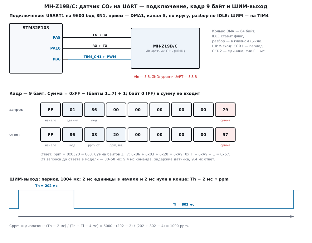
There are two outputs, and they are independent: UART — on request, PWM — by itself, once per period. The sensor may also have an HD pin for zero calibration with a jumper and an analog output (per the manufacturer's documentation, not verified); they are not needed here.
| Sensor pin | STM32F103 | Purpose |
|---|---|---|
| Vin | 5 V | emitter supply |
| GND | GND | ground |
| TX | PA10 | USART1_RX, replies of the sensor |
| RX | PA9 | USART1_TX, commands to the sensor |
| PWM | PB6 | TIM4_CH1, PWM input |
Per the manufacturer's documentation (not verified): supply 4.5…5.5 V, UART
levels 3.3 V, average current up to 60 mA, and peaks up to 150 mA when the
emitter flashes. The F103 drives TX at 3.3 V — that suits the sensor. The
receiving pins are FT: PA10 (p. 31) and PB6 (p. 32) withstand 5 V if an adapter
board with five-volt logic turns up. PA0 with TIM2_CH1_ETR is not taken for the
PWM: it is not FT (p. 29). About the current peaks — in 103д.7.
UART — 9600 baud, 8N1, USART1 on APB2 = 72 MHz: BRR = 72 000 000 / 9600 =
7500 = 0x1D4C, that is 468 + 12/16 = 468.75, exactly what table 192 of RM0008
(p. 800) gives, error 0%. A byte takes 1041.7 µs, a 9-byte frame 9.375 ms; no
more than 960 bytes per second. The exchange is rare: a request and a reply
every few seconds.
103д.2 The 9-byte frame and the checksum
Both the command and the reply are exactly 9 bytes. The command: FF, byte 1 =
0x01, the code, five parameter bytes, the checksum. The reply: FF, the command
code in byte 1, six data bytes, the checksum. This is how the mhz19b driver in
Zephyr 4.4.2 works: it sends FF 01 code … and in the reply to a setting
compares byte 1 with the code.
| Command | Frame | Reply |
|---|---|---|
| 0x86 — read CO₂ | FF 01 86 00 00 00 00 00 79 |
ppm — bytes 2–3 |
| 0x79 — ABC on | FF 01 79 A0 00 00 00 00 E6 |
byte 1 = 0x79 |
| 0x79 — ABC off | FF 01 79 00 00 00 00 00 86 |
byte 1 = 0x79 |
| 0x7D — read ABC | FF 01 7D 00 00 00 00 00 82 |
ABC — byte 7 |
| 0x99 — range 2000 | FF 01 99 00 00 00 07 D0 8F |
byte 1 = 0x99 |
| 0x99 — range 5000 | FF 01 99 00 00 00 13 88 CB |
byte 1 = 0x99 |
| 0x99 — range 10 000 | FF 01 99 00 00 00 27 10 2F |
byte 1 = 0x99 |
| 0x9B — read range | FF 01 9B 00 00 00 00 00 64 |
range — bytes 4–5 |
| 0x87 — zero calibration | FF 01 87 00 00 00 00 00 78 |
per documentation — none |
| 0x88 — span 2000 ppm | FF 01 88 07 D0 00 00 00 A0 |
per documentation — none |
The first eight frames are written ready in Zephyr, with checksums; the driver builds them itself, and all eight matched byte for byte. The codes 0x87 and 0x88 and the place of the span in bytes 3–4 are per the manufacturer's documentation, not verified: they are not in Zephyr.
The checksum is 0xFF minus the sum of bytes 1…7 plus 1, that is simply minus the
sum modulo 256. Byte 0 (FF) is not part of it. If bytes 1…8 are added together
with the checksum, the result is zero modulo 256:
/* контрольная сумма: 0xFF − (байты 1…7) + 1, то есть минус сумма по модулю 256; байт 0 (FF) не входит */
uint8_t mhz_sum(const uint8_t *f)
{
    uint8_t s = 0;
    for (uint32_t i = 1; i < MHZ_FRAME - 1; i++)
        s = (uint8_t)(s + f[i]);
    return (uint8_t)(0xFFu - s + 1u);
}
/* кадр команды: FF 01 cmd, байты 3–4 = w34, байт 5 = 0, байты 6–7 = w67, сумма */
void mhz_cmd_frame(uint8_t cmd, uint16_t w34, uint16_t w67, uint8_t out[MHZ_FRAME])
{
    out[0] = MHZ_HEAD;
    out[1] = MHZ_ADDR;
    out[2] = cmd;
    out[3] = (uint8_t)(w34 >> 8);
    out[4] = (uint8_t)w34;
    out[5] = 0;
    out[6] = (uint8_t)(w67 >> 8);
    out[7] = (uint8_t)w67;
    out[8] = mhz_sum(out);
}
The model's reply at 800 ppm is FF 86 03 20 00 00 00 00 57: ppm in bytes 2–3,
0x0320 = 800. Bytes 4–7 in the model are zeros: what the real sensor puts there
Zephyr does not parse, and it is not verified here. The sum of bytes 1…7 is
0x86 + 0x03 + 0x20 = 169 = 0xA9, and 0xFF − 0xA9 + 1 = 0x57 — exactly the last
byte. Two frequent mistakes: adding byte 0 as well gives 0x58; forgetting the
"+ 1" gives 0x56. Neither matches any frame. One flipped bit (byte 3, bit 4) —
and mhz_check returns −2, MHZ_E_SUM.
The checksum is one byte, and it is weak. Enumerating all 72 single-bit errors
in this frame: 0 missed. Enumerating all 2556 errors of exactly two bits (with a
check that the FF 86 start is intact): 65 missed — every 39th. It misses pairs
where the same bit in two bytes changed in opposite directions, and pairs of top
bits: 0x80 + 0x80 = 0x100 — zero modulo 256; there are 21 such pairs out of 65.
Hence another protection — check that the reply came to its own request (103д.3)
and that the number is plausible.
103д.3 Reception through DMA on IDLE: frame start, timeout and retry
Reception is as in 16б: DMA1, channel 5 (table 78, p. 281), puts bytes into a
64-byte ring circularly. The half and the end of the ring are not needed here:
the reply is 9 bytes followed by a pause. The IDLE flag rises when the line is
silent for a whole character after the last byte (p. 820), and is cleared by the
"read SR, then DR" pair. The handler only sets a flag, and parsing runs in the
main loop: then the driver lives in one thread, and the shared mhz_t does not
need protection from the interrupt.
void USART1_IRQHandler(void)
{
    uint32_t sr = USART1->SR;
    /* IDLE, ORE, NE, FE снимает пара «чтение SR, затем DR»; при RXNE = 1 байт ещё ждёт DMA — не трогаем (16б.3) */
    if ((sr & (USART_SR_IDLE | USART_SR_ORE | USART_SR_NE | USART_SR_FE)) && !(sr & USART_SR_RXNE))
        (void)USART1->DR;
    if (sr & USART_SR_IDLE)
        idle_flag = 1;                           /* разбор — в главном цикле: драйвер живёт в одном потоке */
}
Parsing runs right in the ring (16б.4), from rd to the DMA write position.
The start of a frame is FF followed by a code that can have a reply. Not a
start — shift by a byte. The frame has not fully arrived — exit, rd stays at
its start. The checksum does not match — again shift by one byte, not by nine:
the real start may be inside the rejected bytes:
/* разбор кольца от rd до позиции записи DMA (размер − NDTR): зовут по IDLE, затем таймеры */
void mhz_on_rx(mhz_t *m, uint16_t ndtr, uint32_t now)
{
    uint16_t wr = (uint16_t)(m->size - ndtr);
    uint16_t used;
    uint8_t f[MHZ_FRAME];
    if (wr >= m->size)                                      /* NDTR = 0 в миг перезагрузки */
        wr = 0;
    m->wr = wr;
    used = (uint16_t)(wr >= m->rd ? wr - m->rd : wr + m->size - m->rd);
    if (used > m->hiwater)
        m->hiwater = used;
    while (used >= (m->search ? 2u : MHZ_FRAME)) {
        if (m->search && (at(m, 0) != MHZ_HEAD || !known(at(m, 1)))) {
            skip(m, 1);                                     /* ищем FF и код ответа */
            used--;
            m->n_junk++;
            continue;
        }
        if (used < MHZ_FRAME)
            break;                                          /* кадр пришёл не весь: rd стоит на его начале */
        for (uint16_t i = 0; i < MHZ_FRAME; i++)
            f[i] = at(m, i);
        if ((!m->search && f[0] != MHZ_HEAD) || (m->check_sum && mhz_sum(f) != f[8])) {
            uint16_t n = m->search ? 1u : MHZ_FRAME;        /* ложное начало или порча: искать со следующего байта */
            skip(m, n);
            used = (uint16_t)(used - n);
            m->n_badsum++;
            continue;
        }
        skip(m, MHZ_FRAME);
        used = (uint16_t)(used - MHZ_FRAME);
        on_frame(m, f, now);
    }
    mhz_poll(m, now);
}
The check_sum and search flags are needed only for the experiments below: in
the firmware both are ones. With search = 0 the driver behaves like simple
drivers: before a request it drops the ring and takes nine bytes in a row.
Zephyr reads the reply the same way — nine bytes in a row without searching for
the start.
One request at a time: while a reply is awaited, a second mhz_read call
returns −3, MHZ_E_BUSY, and replies do not get mixed up. No reply within
100 ms — the same command again, three attempts in all:
/* ответа нет за MHZ_REPLY_MS — повтор той же команды, всего MHZ_TRIES попыток, потом событие «тайм-аут» */
void mhz_poll(mhz_t *m, uint32_t now)
{
    if (m->pending && due(now, m->req_at + MHZ_REPLY_MS)) {
        if (++m->tries < MHZ_TRIES) {
            m->n_retry++;
            m->req_at = now;
            if (!m->search)
                m->rd = m->wr;
            tx_cmd(m);
        } else {
            m->pending = 0;
            m->n_tmo++;
            ev(m, MHZ_EV_TIMEOUT, m->cmd, now);
        }
    }
}
In the model the sensor replies 10…30 ms after the command (model
assumption). 120 requests every 5 s — all 120 answered, from request to event
30–50 ms: 9.4 ms command, the delay, 9.4 ms reply and 1 ms until IDLE.
Retries — 0, the highest ring occupancy — 9 bytes, exactly a frame. The sensor
is silent (broken wire, TX and RX swapped) — three attempts, after 300 ms a
"timeout" event. Zephyr waits 1 s for a reply, and the comment to this number
says it was chosen arbitrarily.
Noise. An experiment on 20 000 requests: in every byte of the reply a bit is flipped with probability 0.2%, the byte is lost with probability 0.05% and an extra one is inserted after it with probability 0.05% (so in the model; a real line has fewer errors):
| Parsing | Accepted | Wrong accepted | Largest wrong, ppm | Retries | Timeouts |
|---|---|---|---|---|---|
search for FF and code, checksum |
19 999 | 0 | — | 519 | 1 |
| no checksum | 19 997 | 108 | 64 259 | 178 | 0 |
| nine in a row, checksum | 19 999 | 0 | — | 519 | 1 |
With the checksum there are no wrong values: a corrupted reply is rejected, and 100 ms later it is asked again. One request out of 20 000 got no reply in three attempts. Without the checksum 108 wrong numbers got into the program, up to 64 259 ppm — more than any range. In Zephyr the checksum of the reply to a read is checked, but the reply to a setting is not: only byte 1 is compared there.
Synchronization. In this exchange the pause between replies helps: whatever
is not parsed is dropped before the next request. It is worse when junk arrives
right before the reply itself — line noise, a sensor that has just powered up.
In the model the reply was preceded by the last k bytes of a foreign frame
FF 86 01 FF 86 00 00 00 F4, k = 0…8. In it ppm = 511, and 0x86 in byte 4
gives a second FF 86 inside (model assumption: bytes 4–7 in the model are
arbitrary):
| Parsing | Reply received | Wrong accepted | Retries | Largest delay, ms |
|---|---|---|---|---|
search for FF and code, checksum |
9 of 9 | 0 | 0 | 40 |
| no checksum | 6 of 9 | 3 | 0 | 40 |
| nine in a row, checksum | 9 of 9 | 0 | 8 | 146 |
With search and checksum the junk is skipped and the reply is parsed at once.
Without the checksum at k = 6, 7 and 8 the driver caught on the false FF 86,
accepted 0 ppm and lost the real reply. "Nine in a row" does not lose the reply,
but pays with a retry: the first nine bytes are rejected, the tail waits for the
timeout.
103д.4 Warm-up, range and checking the settings
Warm-up. Per the manufacturer's documentation the sensor needs 3 minutes after power-on (not verified). All that time it answers, and the number looks like the truth. In the model the reading after power-on is too high by 250 · e^(−t / 150 s) ppm (model assumption). Air — 600 ppm, a request every 5 s:
| After power-on | 30 s | 1 min | 2 min | 3 min | 5 min | 10 min | 20 min |
|---|---|---|---|---|---|---|---|
| error, ppm | +205 | +168 | +112 | +75 | +34 | +5 | 0 |
The driver returns the number during warm-up too, but sets valid = 0: of 240
reads the first 35 (up to 175 s) are flagged, the first valid one is at 180 s.
The model shows something else: the 3 minutes of the documentation are a
minimum, not a guarantee. Calibrate only after a long run (103д.5).
Range. The 0x99 command sets the top of the scale: in Zephyr 2000, 5000 or
10 000 ppm, bytes 6–7. The driver does not send other numbers and returns −5,
MHZ_E_ARG. What the sensor does above the range cannot be said without a
document; in the model the number hits the top (model assumption). Air —
3000 ppm:
| Sensor | Range set | Read back (0x9B) | Over UART, ppm | PWM Th, ms |
|---|---|---|---|---|
| ordinary | 2000 | 2000 | 2000 | 1002 |
| ordinary | 5000 | 5000 | 3000 | 602 |
| ordinary | 10 000 | 10 000 | 3000 | 302 |
| "fake" | 2000 | 5000 | 3000 | 602 |
| "fake" | 10 000 | 5000 | 3000 | 602 |
The PWM also depends on the range: at 3000 ppm the high level lasts 602 ms on the 5000 range and 302 ms on 10 000 (103д.6).
Checking the settings. The sensor confirms 0x79 and 0x99 with a frame
carrying the same code, but a confirmation does not mean the setting took
effect. In the model the "fake" replies the same way but changes nothing
(model assumption: how exactly counterfeit sensors differ is not verified
without samples). So after each setting the firmware reads it back — 0x7D and
0x9B — and on a mismatch sets the suspect flag:
static void on_ev(mhz_t *m, uint8_t ev, uint16_t v, uint32_t now)
{
    if (ev == MHZ_EV_PPM) {
        co2_ppm = v;
        co2_valid = m->valid;
        reads++;
        return;
    }
    if (ev == MHZ_EV_TIMEOUT) {
        timeouts++;
        return;                                  /* настройку повторит следующий шаг цикла */
    }
    if (ev == MHZ_EV_ABC) {
        abc_back = v;
        suspect |= v != 0;                       /* выключали — а датчик говорит «включена» */
    } else if (ev == MHZ_EV_RANGE) {
        range_back = v;
        suspect |= v != RANGE;
    }
    if (step < 4)
        step++;
    next_step(now);
}
In the model the ordinary sensor after "ABC off" reads back 0, and the "fake" — 1; the range 2000 of the "fake" reads back as 5000.
103д.5 ABC automatic calibration, zero calibration 0x87 and span 0x88
An NDIR sensor drifts with time. What to do about it in general was already in 103г.6; here — how it is arranged in the MH-Z19 and what comes out in the model. In the model a new sensor is off by +80 ppm and ages by +5 ppm per day (model assumption).
ABC. Per the manufacturer's documentation (not verified) the automatic calibration is on from the factory and once every 24 h from power-on takes the lowest reading of the day as 400 ppm. The command is 0x79: byte 3 = 0xA0 turns it on, 0x00 turns it off. In the model ABC does exactly this (model assumption: the real algorithm is not disclosed). The error at noon, one week:
| Room | ABC | Day 1 | Day 2 | Days 3–7 |
|---|---|---|---|---|
| flat, an hour of airing in the morning (420 ppm) | on | +83 | −14 | −14 |
| room without airing, never below 800 ppm | on | +82 | −398 | −393 |
| same | off | +82 | +87 | +92 … +112 |
In the flat ABC removed the offset: −14 is 420 taken as 400, plus ageing. In the room without airing it took 800 as 400 and began to read almost 400 ppm low — worse than without it. Without ABC the offset stays and grows by 5 ppm per day. Hence the rule: ABC only where the sensor sees outdoor air every day. In a greenhouse, a cellar, a bedroom with the window closed it is turned off and the zero is calibrated by hand.
Zero, 0x87. Per the manufacturer's documentation the command takes the current reading as 400 ppm, and before it the sensor must spend at least 20 minutes in air of about 400 ppm (not verified). In the model the calibration takes the current smoothed reading, and the reading follows the air with a time constant of 50 s (model assumptions). The sensor worked for an hour in a room at 900 ppm, ABC off:
| Case | Before, ppm | Driver reply | Error after 30 min, ppm | After 4 h, ppm |
|---|---|---|---|---|
| outdoors, after 20 min | +80 | 0 | 0 | +1 |
| outdoors, after 2 min | +118 | 0 | −38 | −37 |
| in the room at 900 ppm | +80 | 0 | −500 | −499 |
After 2 minutes outdoors the sensor had not yet caught up with the air, and the −38 ppm stayed for good. In the room the calibration believed that 900 is 400 and spoiled the sensor by 500 ppm. The second rule the driver can check — not earlier than 20 minutes after power-on:
/* калибровка нуля: датчик сейчас на свежем воздухе (около 400 ppm); без force — не раньше 20 мин после включения */
int mhz_zero(mhz_t *m, uint8_t force, uint32_t now)
{
    if (!force && !due(now, m->on_at + MHZ_ZERO_MIN_MS))
        return MHZ_E_EARLY;
    return send(m, MHZ_CMD_ZERO, 0, 0, 0, now);
}
The sensor was powered on right outdoors and a minute later 0x87 was called:
the driver returned −4, MHZ_E_EARLY, and an hour later the error is the same
+80 ppm. With force = 1 the calibration went through in the middle of the
warm-up, and an hour later the error is −167 ppm. But whether the sensor was
outdoors, the driver does not know: that is the concern of whoever presses the
button.
Span, 0x88. The zero shifts the scale, the span changes its slope: a gas of
known concentration is fed to the sensor and the concentration is sent in bytes
3–4 (per the manufacturer's documentation, not verified; a cylinder of
calibration mixture is needed). In the model the slope is off by 6% (model
assumption). After the zero calibration: 2000 ppm reads as 2096, 1000 as
1036; after 0x88 with 2000 — 2000, 1000 and 400 ppm read correctly. A span below
400 ppm the driver does not send: −5, MHZ_E_ARG. And only after the zero —
otherwise the span fixes someone else's offset.
103д.6 PWM output: ppm with a timer in PWM input mode
Per the manufacturer's documentation (not verified) the PWM output repeats with a period of 1004 ms ±5%: 2 ms high at the start, 2 ms low at the end, and the middle 1000 ms is divided in proportion to the concentration. Hence the formula:
Cppm = range · (Th − 2 ms) / (Th + Tl − 4 ms),
where Th is the high time and Tl the low time. The range is the one set by the 0x99 command. In the model at 1000 ppm on the 5000 range: Th = 202 ms, Tl = 802 ms, and the formula gives 5000 · 200 / 1000 = 1000.
Th and Tl are conveniently measured by a timer in PWM input mode (RM0008,
15.3.6, p. 384): both capture channels look at one input TI1, the first on the
rising edge, the second on the falling edge, and the rising edge also resets
the counter. Then CCR1 is the period and CCR2 the high time. TIM4 sits on
APB1 but counts from 72 MHz (13.3); PSC = 7199 gives 10 kHz (p. 418) — a
0.1 ms tick, and the 1004 ms period is 10 040 ticks, which fits in 16 bits even
with the +5% margin:
    /* ШИМ-вход (RM0008, 15.3.6): IC1 и IC2 — оба с TI1, IC1 по фронту, IC2 по спаду, сброс счётчика по TI1FP1 */
    TIM4->PSC = TIM_PSC;
    TIM4->ARR = 0xFFFFu;
    TIM4->EGR = TIM_EGR_UG;                     /* PSC вступает в силу сразу (13.4) */
    TIM4->CCMR1 = TIM_CCMR1_CC1S_0 | TIM_CCMR1_CC2S_1;        /* CC1S = 01 (TI1), CC2S = 10 (TI1) */
    TIM4->CCER = TIM_CCER_CC1E | TIM_CCER_CC2E | TIM_CCER_CC2P;   /* CC1P = 0 — фронт, CC2P = 1 — спад */
    TIM4->SMCR = TIM_SMCR_TS_2 | TIM_SMCR_TS_0 | TIM_SMCR_SMS_2;  /* TS = 101 (TI1FP1), SMS = 100 (сброс) */
    TIM4->DIER = TIM_DIER_CC1IE;
    TIM4->CR1 = TIM_CR1_CEN;
The interrupt is on the rising edge: at this moment CCR1 holds the period that
has just ended, and CCR2 the high time inside it. Reading CCR1 clears
CC1IF (p. 410). The first edge after start-up is skipped: the counter had not
been reset before it.
void TIM4_IRQHandler(void)
{
    if (TIM4->SR & TIM_SR_CC1IF) {               /* нарастающий фронт: CCR1 — период, CCR2 — единица до него */
        uint16_t per = TIM4->CCR1;               /* чтение CCR1 снимает CC1IF */
        uint16_t hi = TIM4->CCR2;
        if (pwm_skip) {
            pwm_skip = 0;                        /* первый фронт после включения: счётчик ещё не сбрасывался */
        } else {
            pwm_per = per;
            pwm_hi = hi;
            pwm_new = 1;
        }
    }
}
The computation is in integers, in ticks, rounded to the nearest. A period
outside 1004 ms ±5% is not the sensor's PWM (broken wire, noise, wrong pin): −6,
MHZ_E_PWM. A high time shorter than 2 ms gives 0, longer than the period minus
2 ms — the whole range:
/* ШИМ-выход: Cppm = диапазон · (Th − 2 мс) / (Th + Tl − 4 мс); th и period — в тиках таймера, к ближайшему целому */
int32_t mhz_pwm_ppm(uint32_t th, uint32_t period, uint16_t range, uint32_t ticks_per_ms)
{
    uint32_t edge = MHZ_PWM_EDGE_MS * ticks_per_ms;
    uint32_t nom = MHZ_PWM_CYCLE_MS * ticks_per_ms;
    uint32_t span;
    if (period < nom - nom * MHZ_PWM_TOL_PCT / 100u || period > nom + nom * MHZ_PWM_TOL_PCT / 100u || th > period)
        return MHZ_E_PWM;                                   /* не ШИМ датчика: обрыв, помеха, не тот вывод */
    if (th <= edge)
        return 0;
    if (th >= period - edge)
        return range;
    span = period - 2u * edge;
    return (int32_t)(((uint32_t)range * (th - edge) * 2u + span) / (2u * span));
}
Why divide by the measured period and not by 1000 ms? The sensor's clock drifts within ±5%, and Th stretches with it. In the model — seven concentrations from 0 to 5000 ppm on the 5000 range, 50 random tick phases each, 350 captures in all for each clock rate:
| Sensor clock rate | ×0.95 | ×1.00 | ×1.05 |
|---|---|---|---|
| period, ms | 953.8 | 1004.0 | 1054.2 |
| error by the formula, ppm, at most | 1 | 0 | 1 |
| error when dividing by 1000 ms, ppm, at most | 250 | 0 | 250 |
By the formula the error is at most 1 ppm: only the rounding of the 0.1 ms tick. Dividing by 1000 ms gives up to 250 ppm near the top of the scale — exactly those 5%.
PWM is slower than UART — one number per 1004 ms — but needs neither a request nor frame parsing. But the range in the formula must be the same as in the sensor: a sensor on 5000 at 3000 ppm gives Th = 602 ms, and the formula with range 2000 yields 1200 ppm instead of 3000.
103д.7 Pitfalls
ABC in a room that is never aired. The automatic calibration takes the daily minimum as 400 ppm. Where the air is never outdoor air, it "repairs" a good sensor: −398 ppm on the second day in the model. Turn ABC off (0x79 with 0x00) and read it back (0x7D).
0x87 not outdoors or too early. Zero calibration believes there are 400 ppm around. In a room at 900 ppm the model gives −500 ppm for good; after 2 minutes outdoors — −38 ppm; a minute after power-on — −167 ppm. At least 20 minutes of operation, and in fresh air.
The checksum over the wrong bytes. The checksum is over bytes 1…7, without
FF, and with "+ 1". With byte 0 it comes out as 0x58, without "+ 1" as 0x56
instead of 0x57: no frame will match.
No checksum. 108 wrong numbers out of 20 000 in the 103д.3 experiment, up to
64 259 ppm, and a false FF 86 start in the data.
PWM: wrong range or a 1000 ms period. The range in the formula is as in the sensor: otherwise 1200 instead of 3000 ppm. Divide by the measured period: otherwise up to 250 ppm when the sensor clock is off by 5%.
A setting is "accepted" but did not take effect. The confirmation of 0x79 and 0x99 guarantees nothing. Counterfeit and remarked sensors are around; how they differ is not verified without samples. Read the settings back (0x7D, 0x9B) and compare: in the model the "fake" answers "5000" to "range 2000".
The first minutes. Warm-up is 3 minutes per the documentation, but in the
model even after 3 minutes it is +75 ppm. A number during warm-up carries the
flag valid = 0.
Current peaks. Per the manufacturer's documentation the average current is up to 60 mA, and at the moment of the emitter flash up to 150 mA (not verified, this is not in the model). A supply from the 5 V pin of a development board through a thin long wire sags at every flash. A capacitor right at the sensor and a separate supply wire; without them expect sensor resets and noise on the UART.
Five volts on the pins. The sensor UART levels are 3.3 V (per the manufacturer's documentation), but adapters can be five-volt. Receive on FT pins: PA10 and PB6 (pp. 31, 32) withstand it, PA0 (p. 29) does not.
103д.8 Summary
- The MH-Z19B/C is an NDIR CO₂ sensor on UART 9600 baud 8N1 (
BRR= 0x1D4C); supply 5 V, levels 3.3 V; the second output is PWM. - The frame is 9 bytes:
FF, byte 1, code, five bytes, checksum = 0xFF − (bytes 1…7) + 1. Read —FF 01 86 00 00 00 00 00 79, ppm — bytes 2–3 of the reply. The checksum catches all 72 single errors, misses 65 of 2556 double ones. - Reception — DMA1, channel 5, into a 64-byte ring, parsing on
IDLEin the main loop: look forFFand a code, check the checksum, shift by a byte. The reply in the model comes after 30–50 ms; no reply — a retry after 100 ms, three attempts. - Without the checksum the experiment gives 108 wrong out of 20 000; with it — 0.
- Warm-up is 3 minutes per the documentation; in the model after 3 minutes still +75 ppm. The range is 2000, 5000 or 10 000 (0x99), read the settings back (0x9B, 0x7D).
- ABC only where the sensor sees outdoor air every day, otherwise −398 ppm in the model; 0x87 — outdoors, not earlier than 20 minutes of operation.
- PWM: Cppm = range · (Th − 2) / (Th + Tl − 4), period 1004 ms; TIM4 in PWM input mode, 0.1 ms tick — error at most 1 ppm, dividing by 1000 ms instead of the period — up to 250 ppm.
Full sources
mhz103f.h — frame, command codes, timings, error codes and functions of the MH-Z19B/C driver.
/* mhz103f.h — раздел 103д: драйвер датчика CO2 MH-Z19B/C (Winsen) по UART без регистров микроконтроллера.
 * Приём — кольцо, в которое пишет DMA (раздел 16б); разбор зовут по паузе в линии (IDLE) с текущим NDTR.
 * Передача и время — функции порта (mhz_port_tx): в прошивке fw103f.c это USART1 и SysTick STM32F103, в стенде
 * host103f.c — модель model103f.py.
 * Кадр — 9 байт: FF, байт 1, команда (в ответе — байт 1), пять байт, контрольная сумма 0xFF − (байты 1…7) + 1.
 * Начало FF, байт 1 = 0x01 в команде, коды 0x86/0x79/0x7D/0x99/0x9B, 0xA0 для ABC, диапазон в байтах 6–7, ppm в
 * ответе — байты 2–3, диапазон — 4–5, ABC — 7, и сумма — как в драйвере mhz19b Zephyr 4.4.2. Команды 0x87 и 0x88,
 * прогрев 3 мин, 20 мин перед калибровкой нуля и ШИМ-выход — по документации производителя, с датчиком не сверено. */
#ifndef MHZ103F_H
#define MHZ103F_H
#include <stdint.h>

#define MHZ_FRAME         9u
#define MHZ_HEAD          0xFFu
#define MHZ_ADDR          0x01u         /* байт 1 команды (в Zephyr — MHZ19B_RESERVED) */
#define MHZ_CMD_READ      0x86u         /* прочитать CO2: ответ — ppm в байтах 2–3 */
#define MHZ_CMD_ZERO      0x87u         /* калибровка нуля: сейчас вокруг 400 ppm (по документации) */
#define MHZ_CMD_SPAN      0x88u         /* калибровка пролёта: ppm в байтах 3–4 (по документации) */
#define MHZ_CMD_ABC       0x79u         /* автокалибровка: байт 3 = 0xA0 — вкл, 0x00 — выкл */
#define MHZ_CMD_ABC_GET   0x7Du         /* ответ — байт 7 */
#define MHZ_CMD_RANGE     0x99u         /* диапазон: байты 6–7, 2000/5000/10000 */
#define MHZ_CMD_RANGE_GET 0x9Bu         /* ответ — байты 4–5 */
#define MHZ_ABC_ON        0xA0u

#define MHZ_REPLY_MS      100u          /* ждать ответ: 9,4 мс команда + задержка датчика + 9,4 мс ответ */
#define MHZ_TRIES         3u            /* попыток одного запроса */
#define MHZ_WARM_MS       180000u       /* прогрев после включения: 3 мин (по документации) */
#define MHZ_ZERO_MIN_MS   1200000u      /* калибровка нуля — не раньше 20 мин работы (по документации) */
#define MHZ_PWM_EDGE_MS   2u            /* ШИМ: 2 мс единицы в начале и 2 мс нуля в конце периода */
#define MHZ_PWM_CYCLE_MS  1004u         /* период ШИМ, ±5 % (по документации) */
#define MHZ_PWM_TOL_PCT   5u

enum { MHZ_OK = 0, MHZ_E_HEAD = -1, MHZ_E_SUM = -2, MHZ_E_BUSY = -3, MHZ_E_EARLY = -4, MHZ_E_ARG = -5, MHZ_E_PWM = -6 };
enum { MHZ_EV_PPM = 0, MHZ_EV_RANGE = 1, MHZ_EV_ABC = 2, MHZ_EV_ACK = 3, MHZ_EV_TIMEOUT = 4 };

typedef struct mhz mhz_t;
typedef void (*mhz_cb)(mhz_t *m, uint8_t ev, uint16_t value, uint32_t now);

struct mhz {
    const volatile uint8_t *ring;       /* кольцо DMA */
    uint16_t size, rd, wr, hiwater;     /* wr — позиция записи DMA при последнем разборе */
    uint8_t check_sum;                  /* 1; 0 — сумму не смотреть (для опыта) */
    uint8_t search;                     /* 1 — искать FF и код, сдвиг на байт; 0 — девять байт подряд (для опыта) */
    uint8_t pending, tries, cmd, valid, abc;
    uint16_t w34, w67, ppm, range;
    uint32_t req_at, on_at;
    mhz_cb cb;
    uint32_t n_good, n_badsum, n_junk, n_req, n_retry, n_tmo, n_stray;
};

/* ── порт: в прошивке — USART1; в стенде — строки к модели ── */
void mhz_port_tx(const uint8_t *p, uint16_t n);

/* ── драйвер ──────────────────────────────────────────────────────────── */
uint8_t mhz_sum(const uint8_t *f);
void mhz_cmd_frame(uint8_t cmd, uint16_t w34, uint16_t w67, uint8_t out[MHZ_FRAME]);
int mhz_check(const uint8_t *f);
void mhz_init(mhz_t *m, const volatile uint8_t *ring, uint16_t size, mhz_cb cb, uint32_t now);
void mhz_on_rx(mhz_t *m, uint16_t ndtr, uint32_t now);
void mhz_poll(mhz_t *m, uint32_t now);
int mhz_read(mhz_t *m, uint32_t now);
int mhz_set_abc(mhz_t *m, uint8_t on, uint32_t now);
int mhz_get_abc(mhz_t *m, uint32_t now);
int mhz_set_range(mhz_t *m, uint16_t range, uint32_t now);
int mhz_get_range(mhz_t *m, uint32_t now);
int mhz_zero(mhz_t *m, uint8_t force, uint32_t now);
int mhz_span(mhz_t *m, uint16_t ppm, uint32_t now);
int32_t mhz_pwm_ppm(uint32_t th, uint32_t period, uint16_t range, uint32_t ticks_per_ms);
uint32_t mhz_next_ms(const mhz_t *m, uint32_t now);

#endif
mhz103f.c — driver: checksum, command frame, ring parsing on IDLE, request with retry, settings, calibration and ppm from PWM.
/* mhz103f.c — раздел 103д: драйвер MH-Z19B/C. Кадр 9 байт с суммой, разбор прямо из кольца DMA по IDLE с поиском
 * начала, запрос с тайм-аутом и повтором, ABC, диапазон, калибровка нуля и пролёта, ppm по ШИМ-выходу. Регистров
 * микроконтроллера здесь нет: тот же файл собирается в прошивку и в стенд на компьютере. */
#include "mhz103f.h"

static int due(uint32_t now, uint32_t t)
{
    return (int32_t)(now - t) >= 0;
}

static uint8_t at(const mhz_t *m, uint16_t k)             /* k-й байт от rd; без деления на размер кольца */
{
    uint32_t i = (uint32_t)m->rd + k;
    if (i >= m->size)
        i -= m->size;
    return m->ring[i];
}

static void skip(mhz_t *m, uint16_t n)
{
    uint32_t i = (uint32_t)m->rd + n;
    if (i >= m->size)
        i -= m->size;
    m->rd = (uint16_t)i;
}

static int known(uint8_t c)                                 /* коды, на которые бывает ответ */
{
    return c == MHZ_CMD_READ || c == MHZ_CMD_ABC || c == MHZ_CMD_ABC_GET || c == MHZ_CMD_RANGE
        || c == MHZ_CMD_RANGE_GET || c == MHZ_CMD_ZERO || c == MHZ_CMD_SPAN;
}

/* контрольная сумма: 0xFF − (байты 1…7) + 1, то есть минус сумма по модулю 256; байт 0 (FF) не входит */
uint8_t mhz_sum(const uint8_t *f)
{
    uint8_t s = 0;
    for (uint32_t i = 1; i < MHZ_FRAME - 1; i++)
        s = (uint8_t)(s + f[i]);
    return (uint8_t)(0xFFu - s + 1u);
}

/* кадр команды: FF 01 cmd, байты 3–4 = w34, байт 5 = 0, байты 6–7 = w67, сумма */
void mhz_cmd_frame(uint8_t cmd, uint16_t w34, uint16_t w67, uint8_t out[MHZ_FRAME])
{
    out[0] = MHZ_HEAD;
    out[1] = MHZ_ADDR;
    out[2] = cmd;
    out[3] = (uint8_t)(w34 >> 8);
    out[4] = (uint8_t)w34;
    out[5] = 0;
    out[6] = (uint8_t)(w67 >> 8);
    out[7] = (uint8_t)w67;
    out[8] = mhz_sum(out);
}

int mhz_check(const uint8_t *f)
{
    if (f[0] != MHZ_HEAD)
        return MHZ_E_HEAD;
    if (mhz_sum(f) != f[8])
        return MHZ_E_SUM;
    return MHZ_OK;
}

void mhz_init(mhz_t *m, const volatile uint8_t *ring, uint16_t size, mhz_cb cb, uint32_t now)
{
    *m = (mhz_t){0};
    m->ring = ring;
    m->size = size;
    m->cb = cb;
    m->check_sum = 1;
    m->search = 1;
    m->range = 5000u;
    m->on_at = now;                                         /* от включения питания датчика */
}

static void ev(mhz_t *m, uint8_t e, uint16_t v, uint32_t now)
{
    if (m->cb)
        m->cb(m, e, v, now);
}

static void tx_cmd(const mhz_t *m)
{
    uint8_t f[MHZ_FRAME];
    mhz_cmd_frame(m->cmd, m->w34, m->w67, f);
    mhz_port_tx(f, MHZ_FRAME);
}

static int send(mhz_t *m, uint8_t cmd, uint16_t w34, uint16_t w67, uint8_t reply, uint32_t now)
{
    if (m->pending)
        return MHZ_E_BUSY;                                  /* один запрос за раз: ответы не перепутаются */
    m->cmd = cmd;
    m->w34 = w34;
    m->w67 = w67;
    if (reply) {
        m->pending = 1;
        m->tries = 0;
        m->n_req++;
        m->req_at = now;
    }
    if (!m->search)
        m->rd = m->wr;                                      /* «девять подряд»: сбросить всё, что было до запроса */
    tx_cmd(m);
    return MHZ_OK;
}

static void on_frame(mhz_t *m, const uint8_t *f, uint32_t now)
{
    uint8_t c = f[1];                                       /* в ответе байт 1 — код команды */
    m->n_good++;
    if (m->pending && c == m->cmd)
        m->pending = 0;
    else
        m->n_stray++;                                       /* ответ без запроса: опоздал после повтора */
    if (c == MHZ_CMD_READ) {
        m->ppm = (uint16_t)(f[2] << 8 | f[3]);
        m->valid = (uint8_t)due(now, m->on_at + MHZ_WARM_MS);   /* в прогреве число есть, но ему не верят */
        ev(m, MHZ_EV_PPM, m->ppm, now);
    } else if (c == MHZ_CMD_RANGE_GET) {
        m->range = (uint16_t)(f[4] << 8 | f[5]);
        ev(m, MHZ_EV_RANGE, m->range, now);
    } else if (c == MHZ_CMD_ABC_GET) {
        m->abc = f[7];
        ev(m, MHZ_EV_ABC, f[7], now);
    } else {
        ev(m, MHZ_EV_ACK, c, now);
    }
}

/* разбор кольца от rd до позиции записи DMA (размер − NDTR): зовут по IDLE, затем таймеры */
void mhz_on_rx(mhz_t *m, uint16_t ndtr, uint32_t now)
{
    uint16_t wr = (uint16_t)(m->size - ndtr);
    uint16_t used;
    uint8_t f[MHZ_FRAME];
    if (wr >= m->size)                                      /* NDTR = 0 в миг перезагрузки */
        wr = 0;
    m->wr = wr;
    used = (uint16_t)(wr >= m->rd ? wr - m->rd : wr + m->size - m->rd);
    if (used > m->hiwater)
        m->hiwater = used;
    while (used >= (m->search ? 2u : MHZ_FRAME)) {
        if (m->search && (at(m, 0) != MHZ_HEAD || !known(at(m, 1)))) {
            skip(m, 1);                                     /* ищем FF и код ответа */
            used--;
            m->n_junk++;
            continue;
        }
        if (used < MHZ_FRAME)
            break;                                          /* кадр пришёл не весь: rd стоит на его начале */
        for (uint16_t i = 0; i < MHZ_FRAME; i++)
            f[i] = at(m, i);
        if ((!m->search && f[0] != MHZ_HEAD) || (m->check_sum && mhz_sum(f) != f[8])) {
            uint16_t n = m->search ? 1u : MHZ_FRAME;        /* ложное начало или порча: искать со следующего байта */
            skip(m, n);
            used = (uint16_t)(used - n);
            m->n_badsum++;
            continue;
        }
        skip(m, MHZ_FRAME);
        used = (uint16_t)(used - MHZ_FRAME);
        on_frame(m, f, now);
    }
    mhz_poll(m, now);
}

/* ответа нет за MHZ_REPLY_MS — повтор той же команды, всего MHZ_TRIES попыток, потом событие «тайм-аут» */
void mhz_poll(mhz_t *m, uint32_t now)
{
    if (m->pending && due(now, m->req_at + MHZ_REPLY_MS)) {
        if (++m->tries < MHZ_TRIES) {
            m->n_retry++;
            m->req_at = now;
            if (!m->search)
                m->rd = m->wr;
            tx_cmd(m);
        } else {
            m->pending = 0;
            m->n_tmo++;
            ev(m, MHZ_EV_TIMEOUT, m->cmd, now);
        }
    }
}

int mhz_read(mhz_t *m, uint32_t now)
{
    return send(m, MHZ_CMD_READ, 0, 0, 1, now);
}

int mhz_set_abc(mhz_t *m, uint8_t on, uint32_t now)
{
    return send(m, MHZ_CMD_ABC, on ? (uint16_t)(MHZ_ABC_ON << 8) : 0u, 0, 1, now);
}

int mhz_get_abc(mhz_t *m, uint32_t now)
{
    return send(m, MHZ_CMD_ABC_GET, 0, 0, 1, now);
}

int mhz_set_range(mhz_t *m, uint16_t range, uint32_t now)
{
    if (range != 2000u && range != 5000u && range != 10000u)
        return MHZ_E_ARG;                                   /* как в Zephyr: только три диапазона */
    return send(m, MHZ_CMD_RANGE, 0, range, 1, now);
}

int mhz_get_range(mhz_t *m, uint32_t now)
{
    return send(m, MHZ_CMD_RANGE_GET, 0, 0, 1, now);
}

/* калибровка нуля: датчик сейчас на свежем воздухе (около 400 ppm); без force — не раньше 20 мин после включения */
int mhz_zero(mhz_t *m, uint8_t force, uint32_t now)
{
    if (!force && !due(now, m->on_at + MHZ_ZERO_MIN_MS))
        return MHZ_E_EARLY;
    return send(m, MHZ_CMD_ZERO, 0, 0, 0, now);
}

/* калибровка пролёта: в датчике газ известной концентрации ppm; только после калибровки нуля */
int mhz_span(mhz_t *m, uint16_t ppm, uint32_t now)
{
    if (ppm <= 400u || ppm > m->range)
        return MHZ_E_ARG;                                   /* пролёт — выше свежего воздуха и в пределах диапазона */
    return send(m, MHZ_CMD_SPAN, ppm, 0, 0, now);
}

/* ШИМ-выход: Cppm = диапазон · (Th − 2 мс) / (Th + Tl − 4 мс); th и period — в тиках таймера, к ближайшему целому */
int32_t mhz_pwm_ppm(uint32_t th, uint32_t period, uint16_t range, uint32_t ticks_per_ms)
{
    uint32_t edge = MHZ_PWM_EDGE_MS * ticks_per_ms;
    uint32_t nom = MHZ_PWM_CYCLE_MS * ticks_per_ms;
    uint32_t span;
    if (period < nom - nom * MHZ_PWM_TOL_PCT / 100u || period > nom + nom * MHZ_PWM_TOL_PCT / 100u || th > period)
        return MHZ_E_PWM;                                   /* не ШИМ датчика: обрыв, помеха, не тот вывод */
    if (th <= edge)
        return 0;
    if (th >= period - edge)
        return range;
    span = period - 2u * edge;
    return (int32_t)(((uint32_t)range * (th - edge) * 2u + span) / (2u * span));
}

/* ближайший срок, к которому драйверу нужен вызов mhz_poll (без учёта приходящих байтов) */
uint32_t mhz_next_ms(const mhz_t *m, uint32_t now)
{
    return m->pending ? m->req_at + MHZ_REPLY_MS : now + 0x7FFFFFFFu;
}
fw103f.c — F103 firmware: USART1 with DMA1 and IDLE, TIM4 in PWM input mode on PB6, setup with read-back and a read every 5 s.
/* fw103f.c — раздел 103д: датчик CO2 MH-Z19B/C на STM32F103 (BluePill), 72 МГц.
 * USART1, 9600 бод: PA9 — TX к RX датчика, PA10 — RX от TX датчика (PA10 — FT). Приём — DMA1, канал 5, по кругу в
 * кольцо 64 байта (раздел 16б); прерывание IDLE только ставит флаг, разбор — в главном цикле, там же тайм-ауты.
 * PB6 (FT) — ШИМ-выход датчика на TIM4_CH1 в режиме ШИМ-входа: CCR1 — период, CCR2 — единица, тик 0,1 мс.
 * При старте: ABC выключить, диапазон 5000, обе настройки прочитать обратно. Затем запрос CO2 раз в 5 с.
 * Результат — в переменных для отладчика. Тактирование до 72 МГц — как в разделе 6; USART1 на APB2 = 72 МГц,
 * TIM4 на APB1 = 36 МГц считает от 72 МГц (13.3). */
#include "stm32f10x.h"
#include "mhz103f.h"

#define CPU_HZ      72000000u
#define BAUD        9600u
#define RX_SIZE     64u                 /* ответ — 9 байт; IDLE после каждого, кольцо с запасом */
#define POLL_MS     10u
#define READ_MS     5000u
#define RANGE       5000u
#define TIM_PSC     7199u               /* 72 МГц / 7200 = 10 кГц: тик 0,1 мс, период 1004 мс = 10 040 тиков */
#define TICKS_MS    10u

_Static_assert(CPU_HZ / BAUD == 7500u && CPU_HZ % BAUD == 0u, "USART1: BRR = 7500 = 0x1D4C — 9600 бод");
_Static_assert(CPU_HZ / (TIM_PSC + 1u) == TICKS_MS * 1000u, "TIM4: 10 кГц");
_Static_assert(1054u * TICKS_MS < 65536u, "период ШИМ +5 % помещается в 16 бит");

static mhz_t D;
static uint8_t rx_ring[RX_SIZE];
static volatile uint32_t ms;
static volatile uint8_t idle_flag, pwm_new, pwm_skip = 1;
static volatile uint16_t pwm_per, pwm_hi;
static uint8_t step;                    /* 0 — ABC выкл, 1 — читать ABC, 2 — диапазон, 3 — читать диапазон, 4 — работа */
volatile uint16_t co2_ppm, abc_back, range_back;
volatile int32_t pwm_ppm;
volatile uint8_t co2_valid, suspect;    /* suspect: настройка не встала — датчик не тот или поддельный */
volatile uint32_t reads, timeouts;

void SysTick_Handler(void)
{
    ms++;
}

/* ── порт драйвера ────────────────────────────────────────────────────── */
void mhz_port_tx(const uint8_t *p, uint16_t n)
{
    for (uint16_t i = 0; i < n; i++) {           /* 9 байт — 9,4 мс; приём идёт через DMA и не мешает */
        while (!(USART1->SR & USART_SR_TXE)) {
        }
        USART1->DR = p[i];
    }
}

void USART1_IRQHandler(void)
{
    uint32_t sr = USART1->SR;
    /* IDLE, ORE, NE, FE снимает пара «чтение SR, затем DR»; при RXNE = 1 байт ещё ждёт DMA — не трогаем (16б.3) */
    if ((sr & (USART_SR_IDLE | USART_SR_ORE | USART_SR_NE | USART_SR_FE)) && !(sr & USART_SR_RXNE))
        (void)USART1->DR;
    if (sr & USART_SR_IDLE)
        idle_flag = 1;                           /* разбор — в главном цикле: драйвер живёт в одном потоке */
}

void TIM4_IRQHandler(void)
{
    if (TIM4->SR & TIM_SR_CC1IF) {               /* нарастающий фронт: CCR1 — период, CCR2 — единица до него */
        uint16_t per = TIM4->CCR1;               /* чтение CCR1 снимает CC1IF */
        uint16_t hi = TIM4->CCR2;
        if (pwm_skip) {
            pwm_skip = 0;                        /* первый фронт после включения: счётчик ещё не сбрасывался */
        } else {
            pwm_per = per;
            pwm_hi = hi;
            pwm_new = 1;
        }
    }
}

static void next_step(uint32_t now)
{
    switch (step) {
    case 0: (void)mhz_set_abc(&D, 0, now); break;
    case 1: (void)mhz_get_abc(&D, now); break;
    case 2: (void)mhz_set_range(&D, RANGE, now); break;
    case 3: (void)mhz_get_range(&D, now); break;
    default: break;
    }
}

static void on_ev(mhz_t *m, uint8_t ev, uint16_t v, uint32_t now)
{
    if (ev == MHZ_EV_PPM) {
        co2_ppm = v;
        co2_valid = m->valid;
        reads++;
        return;
    }
    if (ev == MHZ_EV_TIMEOUT) {
        timeouts++;
        return;                                  /* настройку повторит следующий шаг цикла */
    }
    if (ev == MHZ_EV_ABC) {
        abc_back = v;
        suspect |= v != 0;                       /* выключали — а датчик говорит «включена» */
    } else if (ev == MHZ_EV_RANGE) {
        range_back = v;
        suspect |= v != RANGE;
    }
    if (step < 4)
        step++;
    next_step(now);
}

static void board_init(void)
{
    RCC->AHBENR |= RCC_AHBENR_DMA1EN;
    RCC->APB2ENR |= RCC_APB2ENR_IOPAEN | RCC_APB2ENR_IOPBEN | RCC_APB2ENR_USART1EN;
    RCC->APB1ENR |= RCC_APB1ENR_TIM4EN;
    GPIOA->CRH = (GPIOA->CRH & ~0xFF0u)
               | 0xBu << 4                      /* PA9 — USART1_TX, альтернативная функция */
               | 0x4u << 8;                     /* PA10 — USART1_RX, вход без подтяжки */
    GPIOB->CRL = (GPIOB->CRL & ~(0xFu << 24)) | 0x4u << 24;   /* PB6 — вход без подтяжки: TIM4_CH1 */

    DMA1_Channel5->CCR = 0;                     /* канал выключен: только так пишутся CNDTR и адреса */
    DMA1_Channel5->CPAR = (uint32_t)&USART1->DR;
    DMA1_Channel5->CMAR = (uint32_t)rx_ring;
    DMA1_Channel5->CNDTR = RX_SIZE;
    DMA1->IFCR = DMA_IFCR_CGIF5;
    DMA1_Channel5->CCR = DMA_CCR5_MINC | DMA_CCR5_CIRC | DMA_CCR5_EN;

    USART1->BRR = CPU_HZ / BAUD;                /* 7500 = 0x1D4C: 468 + 12/16 */
    USART1->CR3 = USART_CR3_DMAR | USART_CR3_EIE;
    USART1->CR1 = USART_CR1_UE | USART_CR1_TE | USART_CR1_RE | USART_CR1_IDLEIE;

    /* ШИМ-вход (RM0008, 15.3.6): IC1 и IC2 — оба с TI1, IC1 по фронту, IC2 по спаду, сброс счётчика по TI1FP1 */
    TIM4->PSC = TIM_PSC;
    TIM4->ARR = 0xFFFFu;
    TIM4->EGR = TIM_EGR_UG;                     /* PSC вступает в силу сразу (13.4) */
    TIM4->CCMR1 = TIM_CCMR1_CC1S_0 | TIM_CCMR1_CC2S_1;        /* CC1S = 01 (TI1), CC2S = 10 (TI1) */
    TIM4->CCER = TIM_CCER_CC1E | TIM_CCER_CC2E | TIM_CCER_CC2P;   /* CC1P = 0 — фронт, CC2P = 1 — спад */
    TIM4->SMCR = TIM_SMCR_TS_2 | TIM_SMCR_TS_0 | TIM_SMCR_SMS_2;  /* TS = 101 (TI1FP1), SMS = 100 (сброс) */
    TIM4->DIER = TIM_DIER_CC1IE;
    TIM4->CR1 = TIM_CR1_CEN;

    NVIC_SetPriority(USART1_IRQn, 5);
    NVIC_SetPriority(TIM4_IRQn, 6);
    NVIC_EnableIRQ(USART1_IRQn);
    NVIC_EnableIRQ(TIM4_IRQn);
    SysTick_Config(CPU_HZ / 1000u);
}

int main(void)
{
    uint32_t last = 0, last_read = 0;
    board_init();
    mhz_init(&D, rx_ring, RX_SIZE, on_ev, ms);  /* питание датчика включилось вместе с платой */
    next_step(ms);
    for (;;) {
        uint32_t now = ms;
        if (idle_flag) {
            idle_flag = 0;
            mhz_on_rx(&D, (uint16_t)DMA1_Channel5->CNDTR, now);
        } else if (now - last >= POLL_MS) {
            last = now;
            mhz_poll(&D, now);
            if (step >= 4 && !D.pending && now - last_read >= READ_MS) {
                last_read = now;
                (void)mhz_read(&D, now);
            } else if (step < 4 && !D.pending) {
                next_step(now);                  /* шаг настройки не получил ответа — ещё раз */
            }
        }
        if (pwm_new) {
            pwm_new = 0;
            pwm_ppm = mhz_pwm_ppm(pwm_hi, pwm_per, RANGE, TICKS_MS);
        }
        __WFI();                                /* до тика SysTick, IDLE или фронта ШИМ */
    }
}
Next: section 104 "Thermocouple: MAX31855 and MAX6675" — the thermocouple, the cold junction and ready-made converters on SPI.