 Embedded HandbookApps
22г. Addressable LEDs: WS2812B, SK6812 RGBW and SK6812WWA — protocol, timing, SPI, timer with DMA, power and levels
Section 22.4 showed the essentials: the strip is driven over a single wire, a bit is encoded by the pulse width, and a timer with DMA outputs it without the CPU. This section covers what people stumble on next. Why a strip "worked and then stopped" with a new reel. How SK6812 differs from WS2812B and why code written for one strip does not always suit another. What RGBW and warm-white SK6812WWA frames look like. Three ways to drive the strip — in software, through SPI and with a timer and DMA — with the timing margin, memory and CPU load worked out. And the electrical side: strip current, voltage drop along it, a 3.3 V signal against 5 V.
Sources: RM0008 Rev 17 (STM32F1: table 76 — DMA data width, p. 278;
table 78 — DMA1 requests, p. 281); DocID13587 Rev 17 (STM32F103x8/xB:
pin PB6 — FT, TIM4_CH1, pp. 32–33; table 36 — output levels, p. 65).
WS2812B and SK6812 timing follows the widespread editions of the
manufacturers' datasheets (Worldsemi and Opsco); these documents are not in
the project, so the window values are qualified in the caption at the end. All
numbers below come from the calculation
_verify/leds22b/ref22b.py (Python 3.11, image stm-lab:1) and a run of the
sim22b.c bench on a PC (gcc 12.2.0) and in QEMU 7.2.22 on Cortex-M3
(arm-none-eabi-gcc 12.2.1).
Terms used in the documentation
Term Meaning addressable LED, smart pixel an LED with its own controller, driven by its place in a chain data in / data out (DIN, DOUT) the data input and output of each LED cascade, daisy chain LEDs connected one after another T0H, T0L, T1H, T1L high and low time of bit 0 and bit 1 reset code (RES, TRST) the reset pause that latches a frame GRB, GRBW the colour order in a frame warm white, natural white, cold white warm, neutral and cool white amber a yellow-orange LED channel bit-banging driving a pin from software half transfer, transfer complete (HT, TC) DMA flags at half and at the end of the buffer level shifter a circuit that converts logic levels gamma correction mapping perceived brightness to PWM values power injection feeding power at several points along a strip
22г.1 How the chip works: shifting along the chain and latching on a pause
Each LED contains a small chip with one data input DIN and one output
DOUT. There is no clock: the receiver measures the width of each pulse
itself and decides whether it is a zero or a one. That is why the protocol is
so strict about time — there is no shared clock that would "wait" for a slow
transmitter.
The first chip in the chain takes the first 24 bits (32 for RGBW) and from
then on acts as a repeater: everything that follows is regenerated and sent
out on DOUT. The second chip takes the next 24 bits, and so on. An LED has
no address — its "address" is its place in the chain.
Received bits do not go to the LED dies at once: the chip keeps them in an input register. New colours light up on all LEDs at the same time when the line stays low for longer than the reset pause. After the pause each chip is ready again to take "its own" first bits. Two consequences follow:
- a pause shorter than the reset is not the end of a frame: the next bits pass through the full chips, run past the end of the strip and are lost;
- a frame does not have to be complete: if you send data only for the first ten LEDs, only those will update.
22г.2 WS2812B and SK6812 timing: windows, not numbers
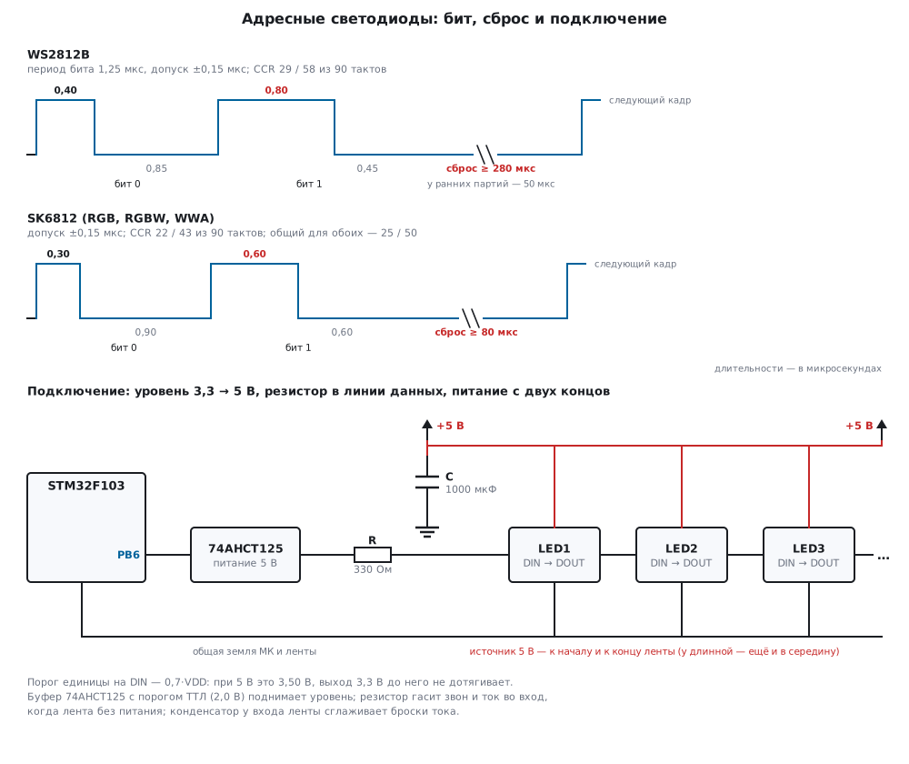
A datasheet gives not a single duration but a window — the nominal value and a tolerance of ±0.15 µs. The calculation below uses these windows:
| WS2812B | SK6812 | |
|---|---|---|
| bit 0: high time T0H | 0.40 µs | 0.30 µs |
| bit 0: low time T0L | 0.85 µs | 0.90 µs |
| bit 1: high time T1H | 0.80 µs | 0.60 µs |
| bit 1: low time T1L | 0.45 µs | 0.60 µs |
| reset pause | ≥ 280 µs on new batches, ≥ 50 µs on early ones | ≥ 80 µs |
The F103 timer counts at 72 MHz: a tick is 13.89 ns, a 1.25 µs bit is 90 ticks,
ARR = 89. The exact CCR values are 28.8 and 57.6 ticks for WS2812B, 21.6 and
43.2 for SK6812; they get rounded. The margin is how far each of the four
durations lies from the edge of its window; the worst one counts:
| CCR for 0 and 1 | T0H / T0L / T1H / T1L, ns | WS2812B margin | SK6812 margin |
|---|---|---|---|
| 29 / 58 (rounded for WS2812B) | 403 / 847 / 806 / 444 | 144 ns | −56 ns |
| 28 / 57 (truncated, as in 22.4) | 389 / 861 / 792 / 458 | 139 ns | −42 ns |
| 22 / 43 (rounded for SK6812) | 306 / 944 / 597 / 653 | −53 ns | 97 ns |
| 25 / 50 (common setting) | 347 / 903 / 694 / 556 | 44 ns | 56 ns |
A negative margin means the value is outside the window. A WS2812B one bit
(0.81 µs) is too long for SK6812: its window ends at 0.75 µs. The reverse is
also wrong: an SK6812 one bit (0.60 µs) is too short for WS2812B — its window
starts at 0.65 µs. So a "universal" library with one strip's timing works on
another only now and then. Some pairs suit both — trying every CCR pair at
ARR = 89 gives 120 such pairs, and the best of them by worst-case margin gives
the same 44 ns as 25 / 50. That is the pair the firmware of this section uses.
#define WS_TIM_HZ   72000000u
#define WS_ARR      89u                     /* период 90 тактов = 1,25 мкс */
#define WS_TICKS(ns) (((ns) * (WS_TIM_HZ / 1000000u) + 500u) / 1000u)   /* с округлением */

#define WS2812_CCR0 WS_TICKS(400u)          /* 0,4 мкс → 28,8 → 29 тактов */
#define WS2812_CCR1 WS_TICKS(800u)          /* 0,8 мкс → 57,6 → 58 тактов */
#define SK6812_CCR0 WS_TICKS(300u)          /* 0,3 мкс → 21,6 → 22 такта  */
#define SK6812_CCR1 WS_TICKS(600u)          /* 0,6 мкс → 43,2 → 43 такта  */
#define ANY_CCR0    25u                     /* 0,347 мкс: в окне у обоих чипов */
#define ANY_CCR1    50u                     /* 0,694 мкс: тоже */
Why the code "worked and then stopped". Early WS2812B chips need a reset pause of 50 µs or more, new batches 280 µs or more. A program written for an old strip pauses 50 µs between frames — 40 bit periods. A new strip does not treat that pause as the end of a frame: the bits of the second frame pass through the full chips and run past the end of the strip. The bench models a chain of three chips and three frames: red and green with a 50 µs pause, blue with a 300 µs pause. A chip with a 50 µs threshold shows red, green, blue. A chip with a 280 µs threshold shows nothing after the first two frames, and after the third it lights up red — the first frame after the previous real reset. If frames come continuously, such a strip freezes or updates only now and then, when the program happens to stall. The cure is a single number: a 300 µs pause (240 periods) is enough for every batch.
Try it in the app: Lab → bench "Addressable LEDs".
22г.3 Byte order: GRB, GRBW and three white channels
WS2812B and SK6812 RGB use 24 bits per LED, with bytes in the order green,
red, blue (GRB), most significant bit first. Orange FF 80 00 in the usual
RGB goes to the strip as 80 FF 00.
SK6812 RGBW uses 32 bits: a separate white die is added to the three
colours, and its byte comes fourth (GRBW). ws_put_rgbw(…, 0x10, 0x20, 0x30,
0x40) gives 20 10 30 40 in the buffer. The white die is not a mix of the
three colours but a phosphor LED: the light is more even, and white comes out
without a bluish or pinkish tint. It is made in several variants — warm,
neutral and cool white; the product name says which one is on the reel, and
the colour temperature is in the datasheet of the batch. The frame per LED is
a third longer, and a frame of 300 LEDs takes 12.08 ms against
9.30 ms for RGB (including reset pauses of 80 and 300 µs), that is, no more
than 82 frames per second against 107.
SK6812WWA is the same chip and the same protocol, 24 bits, but instead of
red, green and blue it has two whites of different colour temperature and an
amber channel. Such a strip is used where the shade of white matters:
accent lighting, light "like an incandescent lamp". The order of the three
bytes and the shades of the channels are described differently by different
batches and sellers, so do not guess: light one byte of the three at a time
(FF 00 00, 00 FF 00, 00 00 FF) and
write down which channel lit up — and check the datasheet of your reel.
22г.4 Software output: why it is on the edge at 72 MHz
The obvious way is to toggle the pin from a loop with counted delays. A tolerance of ±0.15 µs at 72 MHz is 10.8 ticks. Interrupt entry on Cortex-M3 takes 12 cycles (section 7а), that is 167 ns: a single interrupt that arrives during the high level stretches it outside the window, and the bit is read wrongly. So interrupts are disabled for the whole frame.
A frame for 300 LEDs lasts 9000 µs — nine milliseconds without interrupts. A SysTick tick once a millisecond will miss 8 ticks in that time: an interrupt has only one pending flag, and nine events merge into one — the system clock falls behind by 8 ms per frame. UART reception loses bytes during those 9 ms.
The second problem is the loop itself. At 72 MHz the flash runs with two wait
states (section 6), and the execution time depends on code alignment and the
optimisation level. Code tuned precisely at -O2 gives different durations at
-Os or after an edit to a neighbouring function. The method suits a dozen
LEDs in a prototype, not a product.
22г.5 SPI: three SPI bits per strip bit
SPI outputs bits at a constant step, and DMA feeds it bytes without the CPU.
Each strip bit is encoded as a group of SPI bits: zero is 100, one is 110.
SPI1 sits on the APB2 bus (72 MHz); a divider of 32 (BR = 100) gives 2.25 MHz,
an SPI bit of 0.444 µs:
| T0H | T0L | T1H | T1L | WS2812B margin | SK6812 margin | |
|---|---|---|---|---|---|---|
2.25 MHz, 100 / 110 |
444 ns | 889 ns | 889 ns | 444 ns | 61 ns | −139 ns |
4.5 MHz, 110000 / 111000 |
444 ns | 889 ns | 667 ns | 667 ns | −67 ns | 6 ns |
| 9 MHz, 11 bits: 3 / 5 ones | 333 ns | 889 ns | 556 ns | 667 ns | −94 ns | 83 ns |
For WS2812B "100/110" works with a margin of 61 ns, and it is the best option at this frequency — trying groups of 2 to 16 bits finds nothing better. For SK6812 the same encoding falls outside the window: a one lasts 0.889 µs with a limit of 0.75 µs — 139 ns over. The nearest SPI1 frequencies (dividers 16 and 8) give SK6812 either only 6 ns of margin with 6 bits per bit, or 83 ns — but at the cost of 11 SPI bits per strip bit: 33 bytes per RGB LED and 44 per RGBW instead of 9 and 12. The timer does not have this problem: the CCR step is 13.89 ns, not 444 ns.
One encoder serves all variants — ws_spi_encode(dst, src, n, nbits, ones0,
ones1). The byte A5 in the "100/110" encoding turns into the three bytes D3 49 A6.
The bench decodes the encoded A5 00 FF back into durations:
ones are only 1 and 2 SPI bits long, zeros 1 and 2, nothing else.
    SPI1->CR1 = SPI_CR1_MSTR | SPI_CR1_SSM | SPI_CR1_SSI
              | SPI_CR1_BR_2                            /* BR = 100: 72 МГц / 32 = 2,25 МГц */
              | SPI_CR1_SPE;
    SPI1->CR2 = SPI_CR2_TXDMAEN;

    DMA1_Channel3->CPAR = (uint32_t)&SPI1->DR;
    DMA1_Channel3->CCR = DMA_CCR3_MINC | DMA_CCR3_DIR;  /* 8 бит, один проход */
The SPI1_TX request goes to DMA1 channel 3 (table 78 of RM0008). Two subtle
points. The last byte of the buffer is zero: then the MOSI line stays low
after the transfer. And the reset pause is easier to time with a timer than to
spend buffer on it: 280 µs at a 0.444 µs step is 630 SPI bits, 79 bytes of zeros.
22г.6 Timer and DMA: a double buffer
The method from 22.4: a timer in PWM mode with the bit period, and DMA writes
the next duration to CCR1 on every update. In a product on F103 you use
TIM4_CH1 on pin PB6: the TIM4_UP request goes to DMA1 channel 7
(table 78 of RM0008), and PB6 tolerates 5 V (FT, DocID13587, p. 32) — this
will be useful in 22г.9.
A full buffer — 24 half-words per LED — is expensive for a long strip (22г.7). A double buffer costs 96 slots: DMA reads them in a circle, the half-transfer (HT) and transfer-complete (TC) interrupts tell which half has been freed, and the program fills it with the next bits. A half is 48 slots, two RGB LEDs, 60 µs, 4320 CPU cycles between interrupts.
    TIM4->PSC = 0;                                      /* 72 МГц: APB1 36 МГц × 2 */
    TIM4->ARR = WS_ARR;                                 /* 90 тактов = 1,25 мкс */
    TIM4->CCR1 = 0;
    TIM4->CCMR1 = TIM_CCMR1_OC1M_2 | TIM_CCMR1_OC1M_1   /* ШИМ, режим 1 */
                | TIM_CCMR1_OC1PE;                      /* CCR1 в силе с обновления */
    TIM4->CCER = TIM_CCER_CC1E;
    TIM4->CR1 = TIM_CR1_ARPE;
    TIM4->DIER = TIM_DIER_UDE;                          /* запрос DMA на каждом обновлении */

    DMA1_Channel7->CPAR = (uint32_t)&TIM4->CCR1;
    DMA1_Channel7->CMAR = (uint32_t)ws.buf;
    DMA1_Channel7->CCR = DMA_CCR7_MINC | DMA_CCR7_CIRC | DMA_CCR7_DIR
                       | DMA_CCR7_MSIZE_0 | DMA_CCR7_PSIZE_0      /* 16 бит → 16 бит */
                       | DMA_CCR7_HTIE | DMA_CCR7_TCIE | DMA_CCR7_PL_1;
The OC1PE preload is required: DMA writes CCR1 at the start of a period,
and without preload the new value would take effect in the same period — the
pulse could be cut short or doubled (shadow registers — section 13.4). With
preload the output lags the DMA by one period, and the first period runs with
CCR1 = 0 — this only lengthens the pause before the frame a little.
Filling is a single function: bits from the colour bytes, most significant
first, and zeros after the data. CCR = 0 keeps the line low for the whole
period, so the reset pause comes out by itself, without a separate timer. The
timer may be stopped not as soon as the stream ends, but only when DMA has read
the last filled half:
int ws_dma_irq(ws_dma_t *d, uint32_t half)
{
    /* Половина half только что прочитана, DMA читает другую — эту можно переписать. */
    int end = ws_stream_fill(&d->s, &d->buf[half * WS_HALF], WS_HALF);
    if (d->after_end || end)
        d->after_end++;
    /* Конец потока лёг в половину, заполненную после прерывания k. DMA прочтёт её
       к прерыванию k + 2 — только тогда таймер можно остановить. */
    return d->after_end >= 3u;
}
void DMA1_Channel7_IRQHandler(void)
{
    uint32_t isr = DMA1->ISR;
    uint32_t half = (isr & DMA_ISR_TCIF7) ? 1u : 0u;    /* TC — вторая половина свободна */
    DMA1->IFCR = DMA_IFCR_CHTIF7 | DMA_IFCR_CTCIF7 | DMA_IFCR_CGIF7;
    if (ws_dma_irq(&ws, half)) {
        TIM4->CR1 &= ~TIM_CR1_CEN;                      /* на линии ноль: CCR давно 0 */
        DMA1_Channel7->CCR &= ~DMA_CCR7_EN;
        ws_busy = 0;
    }
}
The bench models DMA in circular mode and late interrupts and compares every slot read against the full buffer:
| Strip | Reset pause | Interrupt delay | Slots read | Errors | Zeros after data |
|---|---|---|---|---|---|
| 300 RGB | 240 | 0 | 7440 | 0 | 240 |
| 300 RGB | 240 | 48 periods (60 µs) | 7488 | 0 | 288 |
| 300 RGB | 240 | 49 periods | 7489 | 62 | 289 |
| 1 RGB | 240 | 0 | 288 | 0 | 264 |
| 300 RGB | 64 (SK6812) | 0 | 7296 | 0 | 96 |
The interrupt may be late (together with the fill time) by a whole half — 48 periods, 60 µs. One period more, and DMA reads a half that has not been rewritten yet, and 62 slots go out with stale bits. That is why this interrupt gets a high priority, and long sections with interrupts disabled elsewhere in the program are not acceptable — 60 µs is the limit.
22г.7 Memory and CPU: what to choose
For a strip of 300 LEDs (F103C8 has 20 KB of RAM, 20480 bytes):
| Method | RGB buffer | RGBW buffer | CPU during output |
|---|---|---|---|
| software output | 0 | 0 | busy for the whole frame, interrupts disabled for 9000 µs |
| SPI, 2.25 MHz, 3 bits | 2700 bytes | 3600 bytes | free; the frame is encoded beforehand |
| SPI, 9 MHz, 11 bits (SK6812) | 9900 bytes | 13200 bytes | free; encoding beforehand |
| timer, full 16-bit buffer | 14400 bytes (70.3 %) | 19200 bytes (93.8 %) | free |
| timer, full 8-bit buffer | 7200 bytes | 9600 bytes | free |
| timer, double buffer | 192 bytes | 192 bytes | an interrupt every 60 µs |
The colours themselves take another 900 bytes for RGB and 1200 for RGBW; they are needed with any method. The tail of reset zeros in a full buffer is 240 slots, 480 bytes.
A full buffer can be halved: the F1 DMA reads a byte from memory and writes it to a
16-bit register, filling the upper bits with zeros (table 76 of RM0008).
A CCR of at most 89 fits in a byte, so MSIZE = 8 bits, PSIZE = 16
bits — and 24 bytes per LED instead of 48.
Bottom line: for short strips any hardware method will do; for 300 RGBW LEDs a full buffer eats almost all the RAM — use a double buffer. SPI is the simplest, but for SK6812 "100/110" does not work at the SPI1 frequencies of F103. The firmware of this section uses the timer, a double buffer and the common 25 / 50 timing: 1168 bytes of code and 400 bytes of RAM with 60 LEDs.
22г.8 Power: current, drop along the strip, capacitor and resistor
The LED current is proportional to the channel brightness: inside the chip there is a current source per die and PWM. A widespread estimate is about 20 mA per channel at a value of 255, up to 60 mA per RGB LED in white and up to 80 mA for RGBW. A strip of 300 in full white draws 18 A (90 W at 5 V), RGBW 24 A. The exact currents differ between manufacturers; for a power-supply budget take these upper estimates or measure your reel.
The strip copper is thin. Example: rails 10 mm wide of 35 µm foil have 0.0491 Ω per metre each, 0.0983 Ω per metre for the "plus — minus" loop. Model: 60 LEDs per metre, 60 mA each, current independent of voltage. The largest drop:
| Strip and power feed | Drop |
|---|---|
| 1 m, fed from one end | 0.17 V |
| 5 m, from one end | 4.41 V |
| 5 m, from both ends | 1.10 V |
| 5 m, fed every metre | 0.04 V |
Over four volts is not an exact figure but a sign that the model does not apply here: at the end of a five-metre strip fed from one end the LEDs simply get no voltage. Blue and green go out first — they need more voltage than red, so white turns yellow and red towards the end of the strip. The cure is feeding power at both ends, and for a long strip also in the middle and every one or two metres, with wire thicker than the strip traces.
Three more wiring rules (figure):
- A 1000 µF capacitor between +5 V and ground at the strip input. The strip switches amperes on and off within microseconds; without an energy reserve at the input the voltage sags and rings on the supply wires.
- A 300–500 Ω resistor in series with the data line, close to the transmitter. It damps ringing on the wire and limits the current into the input when the strip is unpowered but the microcontroller already outputs a one: through the input protection diodes no more than 11.0 mA at 300 Ω and 6.6 mA at 500 Ω.
- A common ground for the microcontroller and the strip, with the data wire next to the ground wire. Without a common ground, signal levels mean nothing.
22г.9 Signal level: 3.3 V against 5 V
The DIN input treats a voltage of at least 0.7·VDD as a one. With a 5 V supply
that is 3.50 V. An F103 output on a 3.3 V supply gives about 3.3 V unloaded —
0.20 V below the threshold; the guaranteed minimum from table 36 of
DocID13587 is VDD − 0.4 = 2.9 V, 0.60 V below. That the strip still
often works is thanks to the real thresholds, which are usually lower than
the guaranteed ones. But the real threshold depends on the batch, temperature and
the strip supply voltage: at 4.5 V (a sagging supply) the threshold is 3.15 V and the strip
works, while at a full 5 V on a new reel it "works one moment and not the next".
Hence the typical puzzle: on the bench from a lab supply everything is
fine, in the product the first LED flashes random colours.
Solutions, from reliable to simple:
- A buffer with TTL-level inputs, powered from 5 V: 74AHCT125 or 74HCT245. Their input-high threshold is 2.0 V, a margin of 1.3 V from 3.3 V and 0.9 V even from the guaranteed 2.9 V. The letter T in the name is essential: 74HC125 and 74AHC125 at 5 V have the same 0.7·VDD threshold and will fix nothing.
- A "sacrificial" first LED. It is powered through a silicon diode:
VDD about 4.3 V, threshold 0.7·4.3 = 3.01 V — 0.29 V below 3.3 V. Its
DOUToutput already gives 4.3 V pulses, which the rest of the strip receives reliably. The price: one LED runs on a reduced supply, and with the guaranteed 2.9 V there is no margin here either (−0.11 V). - Open drain with a pull-up to 5 V. PB6 tolerates 5 V (FT), so the output can be set to open drain and the line pulled up to +5 V with a 1 kΩ resistor. The price is the rising edge: with a line and input capacitance of about 50 pF (as an example) the line reaches the 3.5 V threshold in 60 ns, shortening the high level by as much; the current into the open switch is 5.0 mA.
22г.10 Gamma correction, brightness and current limiting
The eye perceives brightness non-linearly: a value of 128 out of 255 looks noticeably
brighter than "half". A smooth fade on a linear scale seems fast near the
top and "steppy" near the bottom. Gamma correction converts the
desired brightness into a PWM value: round(255·(i/255)^2,2). After it
128 becomes 56, and 64 becomes 12.
The price is losing dark shades: the first 15 values (0…14) give zero, and only 184 distinct levels out of 256 remain. A smooth "sunrise" therefore starts with a jump. The global brightness is applied after gamma: at brightness 127 a value of 255 becomes 127, and 128 becomes 28.
Current limiting is a software fuse for the power supply. The current is estimated from the sum of the channel values (20 mA per channel at 255), and if it exceeds the budget, all channels are multiplied by one factor:
uint32_t ws_limit(uint8_t *buf, uint32_t nbytes, uint32_t ma_full, uint32_t budget_ma)
{
    uint32_t need = ws_current_ma(buf, nbytes, ma_full);
    if (need <= budget_ma)
        return 256u;
    uint32_t scale = budget_ma * 256u / need;   /* множитель в долях 1/256, всегда меньше 256 */
    for (uint32_t i = 0; i < nbytes; i++)
        buf[i] = (uint8_t)((buf[i] * scale) >> 8);
    return scale;
}
300 LEDs in white ask for 18000 mA; with a 2000 mA budget the factor is 28/256, each channel becomes 27, and the current estimate is 1905 mA. The factor is the same for all channels, so the hues are preserved. The limiter goes last — after gamma and global brightness — otherwise it counts different numbers from those sent to the strip.
22г.11 On the oscilloscope: what to look at
Probe on DIN of the first LED (after the resistor and the buffer), ground to
the strip ground next to it, with a short spring (36а.2). Timebase 0.5–1 µs per
division.
- Pulse widths. The positive pulse width automatic measurement or cursors (36е): with this section's firmware they are 0.35 and 0.69 µs (25 and 50 ticks). Compare with the windows of 22г.2 for your chip. Compare at the strip input: a long wire and the buffer stretch the edges.
- Levels. The top of a pulse at
DINshould be at least 3.5 V (with a buffer, about 5 V). If it shows a "shelf" around 3.3 V, there is no buffer or it is not a TTL one. - Gaps between bytes. With SPI without DMA, or with interrupts in the middle of a transfer, lengthened zeros appear between bytes — the bit stretches past the T0L or T1L window. A timer with DMA has no gaps: every period is 1.25 µs.
- Reset pause. Trigger on timeout or on pulse width (36д.13, 36д.8): a low level longer than 50 µs catches the start of each frame. Use a cursor to measure the pause between frames — at least 280 µs for new WS2812B.
- A long frame. A logic analyzer with a WS2812 decoder (36а.6) shows the colour of each LED — easier than counting pulses by eye.
22г.12 Pitfalls
A new reel "froze" or updates only every other time. The pause between frames is 50 µs, but new WS2812B need 280 µs: frames merge, and the strip shows the first frame after a random long pause. Use a 300 µs pause.
WS2812B code on SK6812 gives random colours. A one of 0.81 µs is longer than the SK6812 window (up to 0.75 µs). The common timing of 25 / 50 ticks suits both.
SPI "100/110" on SK6812 does not work on every strip. A one of 0.889 µs falls outside the window by 139 ns. A timer with DMA, or SPI at 9 MHz with 11 bits per bit.
Red and blue swapped, "orange" turned green. The order is GRB, not RGB. On SK6812WWA check the channel order one at a time.
White on RGBW looks "dirty", or the colours shifted by one channel. You sent 24 bits per LED instead of 32: each following LED gets shifted bytes.
The first LED flickers and the others repeat it. A 3.3 V level against a 3.5 V threshold. A 74AHCT125 buffer, not a 74HC125.
The strip turns yellow towards the end. Supply drop along the strip. Power at both ends and in the middle.
The strip flickers when the program takes interrupts. The double buffer cannot keep up: the handler was more than 60 µs late. Raise the DMA priority, do not keep interrupts disabled for longer.
The power supply goes into protection on white. 300 LEDs draw 18 A. Software current limiting.
22г.13 Summary
- A chip takes the first 24 bits (32 for RGBW) and passes the rest on; the colours light up after the reset pause.
- Windows: WS2812B — 0.40 / 0.80 µs, SK6812 — 0.30 / 0.60 µs, tolerance ±0.15 µs; reset — 280 µs for new WS2812B, 50 for early ones, 80 for SK6812. A 300 µs pause suits all of them.
- Timer at 72 MHz:
ARR = 89; WS2812B — CCR 29 / 58 (margin 144 ns), SK6812 — 22 / 43 (97 ns), both — 25 / 50 (44 and 56 ns). - Software output: a tolerance of 10.8 ticks is less than interrupt entry (12); 300 LEDs mean 9 ms without interrupts.
- SPI at 2.25 MHz "100/110" works for WS2812B (margin 61 ns), not for SK6812 (−139 ns).
- Double buffer: 192 bytes instead of 14400, an interrupt every 60 µs; it may be late by 48 periods.
- Power: up to 60 mA per RGB LED and 80 mA per RGBW; 300 of them draw 18 A; feed at both ends (1.10 V instead of 4.41 V of drop over 5 m), a 1000 µF capacitor, a 300–500 Ω resistor in the data line.
- Level: a 3.50 V threshold at 5 V — a 74AHCT125 buffer with a 2.0 V threshold or a "sacrificial" LED on a diode.
- Gamma 2.2: 128 → 56, 184 levels out of 256; current limiting goes after gamma and brightness.
Full sources
leds22b.h — timing in ticks, byte order, the bit stream, the double buffer, SPI, brightness.
/* leds22b.h — раздел 22г: адресные светодиоды WS2812B, SK6812 RGBW и SK6812WWA.
 * Без регистров: кодирование бит для ШИМ и для SPI, поток с двойным буфером,
 * гамма-коррекция и ограничение тока. Тот же код — в прошивке fw22b.c и в стенде sim22b.c. */
#ifndef LEDS22B_H
#define LEDS22B_H
#include <stdint.h>

/* ── тайминги в тактах таймера 72 МГц ─────────────────────────────────── */
#define WS_TIM_HZ   72000000u
#define WS_ARR      89u                     /* период 90 тактов = 1,25 мкс */
#define WS_TICKS(ns) (((ns) * (WS_TIM_HZ / 1000000u) + 500u) / 1000u)   /* с округлением */

#define WS2812_CCR0 WS_TICKS(400u)          /* 0,4 мкс → 28,8 → 29 тактов */
#define WS2812_CCR1 WS_TICKS(800u)          /* 0,8 мкс → 57,6 → 58 тактов */
#define SK6812_CCR0 WS_TICKS(300u)          /* 0,3 мкс → 21,6 → 22 такта  */
#define SK6812_CCR1 WS_TICKS(600u)          /* 0,6 мкс → 43,2 → 43 такта  */
#define ANY_CCR0    25u                     /* 0,347 мкс: в окне у обоих чипов */
#define ANY_CCR1    50u                     /* 0,694 мкс: тоже */

/* пауза сброса в периодах бита 1,25 мкс */
#define WS_RESET_OLD   40u                  /* 50 мкс — ранние WS2812B */
#define WS_RESET_NEW  240u                  /* 300 мкс — с запасом над 280 мкс */
#define SK_RESET       64u                  /* 80 мкс — SK6812 */

/* ── порядок байтов в ленте ───────────────────────────────────────────── */
void ws_put_rgb(uint8_t *buf, uint32_t i, uint8_t r, uint8_t g, uint8_t b);           /* G R B   */
void ws_put_rgbw(uint8_t *buf, uint32_t i, uint8_t r, uint8_t g, uint8_t b, uint8_t w); /* G R B W */

/* ── поток бит в отсчёты ШИМ: данные, затем нули сброса ───────────────── */
typedef struct {
    const uint8_t *data;    /* байты в порядке выдачи */
    uint32_t bits, pos;     /* всего бит и следующий бит */
    uint32_t tail;          /* сколько нулевых отсчётов сброса осталось */
    uint16_t c0, c1;        /* CCR для нуля и для единицы */
} ws_stream_t;

void ws_stream_start(ws_stream_t *s, const uint8_t *data, uint32_t nbytes,
                     uint32_t reset_slots, uint16_t c0, uint16_t c1);
int ws_stream_fill(ws_stream_t *s, uint16_t *dst, uint32_t n);   /* 1 — поток кончился */

/* ── двойной буфер: DMA читает одну половину, прерывание заполняет другую ── */
#define WS_HALF 48u                         /* отсчётов в половине: два светодиода RGB */
typedef struct {
    ws_stream_t s;
    uint16_t buf[2u * WS_HALF];
    uint8_t after_end;                      /* прерываний после конца потока */
} ws_dma_t;

void ws_dma_prepare(ws_dma_t *d, const uint8_t *data, uint32_t nbytes,
                    uint32_t reset_slots, uint16_t c0, uint16_t c1);
int ws_dma_irq(ws_dma_t *d, uint32_t half);   /* half: 0 — после HT, 1 — после TC; 1 — стоп */

/* ── SPI: каждый бит ленты — nbits бит SPI, из них первые ones0/ones1 — единицы ── */
uint32_t ws_spi_encode(uint8_t *dst, const uint8_t *src, uint32_t n,
                       uint32_t nbits, uint32_t ones0, uint32_t ones1);   /* вернуть байт SPI */

/* ── яркость ──────────────────────────────────────────────────────────── */
extern const uint8_t ws_gamma[256];         /* round(255 * (i / 255)^2,2) */
void ws_apply_gamma(uint8_t *buf, uint32_t nbytes, uint8_t bright);
uint32_t ws_current_ma(const uint8_t *buf, uint32_t nbytes, uint32_t ma_full);
uint32_t ws_limit(uint8_t *buf, uint32_t nbytes, uint32_t ma_full, uint32_t budget_ma);

#endif
leds22b.c — register-free encoding: the part shared by the firmware and the bench.
/* leds22b.c — раздел 22г: кодирование и яркость для адресных светодиодов (без регистров). */
#include "leds22b.h"

void ws_put_rgb(uint8_t *buf, uint32_t i, uint8_t r, uint8_t g, uint8_t b)
{
    uint8_t *p = &buf[i * 3u];
    p[0] = g;               /* первым идёт зелёный */
    p[1] = r;
    p[2] = b;
}

void ws_put_rgbw(uint8_t *buf, uint32_t i, uint8_t r, uint8_t g, uint8_t b, uint8_t w)
{
    uint8_t *p = &buf[i * 4u];
    p[0] = g;
    p[1] = r;
    p[2] = b;
    p[3] = w;               /* белый кристалл — четвёртым байтом */
}

void ws_stream_start(ws_stream_t *s, const uint8_t *data, uint32_t nbytes,
                     uint32_t reset_slots, uint16_t c0, uint16_t c1)
{
    s->data = data;
    s->bits = nbytes * 8u;
    s->pos = 0;
    s->tail = reset_slots;
    s->c0 = c0;
    s->c1 = c1;
}

int ws_stream_fill(ws_stream_t *s, uint16_t *dst, uint32_t n)
{
    for (uint32_t k = 0; k < n; k++) {
        if (s->pos < s->bits) {
            uint32_t bit = (s->data[s->pos >> 3] >> (7u - (s->pos & 7u))) & 1u;   /* старший первым */
            dst[k] = bit ? s->c1 : s->c0;
            s->pos++;
        } else {
            dst[k] = 0;     /* CCR = 0: весь период низкий уровень — это и есть сброс */
            if (s->tail)
                s->tail--;
        }
    }
    return s->pos >= s->bits && s->tail == 0u;
}

void ws_dma_prepare(ws_dma_t *d, const uint8_t *data, uint32_t nbytes,
                    uint32_t reset_slots, uint16_t c0, uint16_t c1)
{
    ws_stream_start(&d->s, data, nbytes, reset_slots, c0, c1);
    d->after_end = 0;
    if (ws_stream_fill(&d->s, d->buf, 2u * WS_HALF))   /* обе половины — до старта */
        d->after_end = 1;
}

int ws_dma_irq(ws_dma_t *d, uint32_t half)
{
    /* Половина half только что прочитана, DMA читает другую — эту можно переписать. */
    int end = ws_stream_fill(&d->s, &d->buf[half * WS_HALF], WS_HALF);
    if (d->after_end || end)
        d->after_end++;
    /* Конец потока лёг в половину, заполненную после прерывания k. DMA прочтёт её
       к прерыванию k + 2 — только тогда таймер можно остановить. */
    return d->after_end >= 3u;
}

uint32_t ws_spi_encode(uint8_t *dst, const uint8_t *src, uint32_t n,
                       uint32_t nbits, uint32_t ones0, uint32_t ones1)
{
    uint32_t out = 0, acc = 0, have = 0;
    for (uint32_t i = 0; i < n; i++) {
        for (int b = 7; b >= 0; b--) {
            uint32_t ones = ((src[i] >> b) & 1u) ? ones1 : ones0;
            for (uint32_t k = 0; k < nbits; k++) {
                acc = (acc << 1) | (k < ones);      /* сначала единицы, потом нули */
                if (++have == 8u) {
                    dst[out++] = (uint8_t)acc;
                    acc = 0;
                    have = 0;
                }
            }
        }
    }
    if (have)                                       /* добить последний байт нулями */
        dst[out++] = (uint8_t)(acc << (8u - have));
    return out;
}

const uint8_t ws_gamma[256] = {
      0,   0,   0,   0,   0,   0,   0,   0,   0,   0,   0,   0,   0,   0,   0,   1,
      1,   1,   1,   1,   1,   1,   1,   1,   1,   2,   2,   2,   2,   2,   2,   2,
      3,   3,   3,   3,   3,   4,   4,   4,   4,   5,   5,   5,   5,   6,   6,   6,
      6,   7,   7,   7,   8,   8,   8,   9,   9,   9,  10,  10,  11,  11,  11,  12,
     12,  13,  13,  13,  14,  14,  15,  15,  16,  16,  17,  17,  18,  18,  19,  19,
     20,  20,  21,  22,  22,  23,  23,  24,  25,  25,  26,  26,  27,  28,  28,  29,
     30,  30,  31,  32,  33,  33,  34,  35,  35,  36,  37,  38,  39,  39,  40,  41,
     42,  43,  43,  44,  45,  46,  47,  48,  49,  49,  50,  51,  52,  53,  54,  55,
     56,  57,  58,  59,  60,  61,  62,  63,  64,  65,  66,  67,  68,  69,  70,  71,
     73,  74,  75,  76,  77,  78,  79,  81,  82,  83,  84,  85,  87,  88,  89,  90,
     91,  93,  94,  95,  97,  98,  99, 100, 102, 103, 105, 106, 107, 109, 110, 111,
    113, 114, 116, 117, 119, 120, 121, 123, 124, 126, 127, 129, 130, 132, 133, 135,
    137, 138, 140, 141, 143, 145, 146, 148, 149, 151, 153, 154, 156, 158, 159, 161,
    163, 165, 166, 168, 170, 172, 173, 175, 177, 179, 181, 182, 184, 186, 188, 190,
    192, 194, 196, 197, 199, 201, 203, 205, 207, 209, 211, 213, 215, 217, 219, 221,
    223, 225, 227, 229, 231, 234, 236, 238, 240, 242, 244, 246, 248, 251, 253, 255,
};

void ws_apply_gamma(uint8_t *buf, uint32_t nbytes, uint8_t bright)
{
    /* сначала гамма, потом общая яркость: так ступени у тёмных цветов не теряются дважды */
    for (uint32_t i = 0; i < nbytes; i++)
        buf[i] = (uint8_t)((ws_gamma[buf[i]] * (bright + 1u)) >> 8);
}

uint32_t ws_current_ma(const uint8_t *buf, uint32_t nbytes, uint32_t ma_full)
{
    uint32_t sum = 0;
    for (uint32_t i = 0; i < nbytes; i++)
        sum += buf[i];
    return sum * ma_full / 255u;    /* ток канала пропорционален скважности его ШИМ */
}

uint32_t ws_limit(uint8_t *buf, uint32_t nbytes, uint32_t ma_full, uint32_t budget_ma)
{
    uint32_t need = ws_current_ma(buf, nbytes, ma_full);
    if (need <= budget_ma)
        return 256u;
    uint32_t scale = budget_ma * 256u / need;   /* множитель в долях 1/256, всегда меньше 256 */
    for (uint32_t i = 0; i < nbytes; i++)
        buf[i] = (uint8_t)((buf[i] * scale) >> 8);
    return scale;
}
fw22b.c — STM32F103 firmware: TIM4 + DMA1 with a double buffer, or SPI1 + DMA1.
/* fw22b.c — раздел 22г: адресная лента от STM32F103 (BluePill), 72 МГц.
 * Способ 1 (основной): TIM4_CH1 на PB6, DMA1 Channel7 по событию обновления TIM4 (TIM4_UP),
 *   двойной буфер с прерываниями на половине (HT) и в конце (TC).
 * Способ 2 (WS22B_SPI): SPI1, MOSI на PA7, 72 МГц / 32 = 2,25 МГц, «100/110», DMA1 Channel3 (SPI1_TX).
 * Каналы DMA — по таблице 78 RM0008. Тактирование до 72 МГц — как в разделе 6 (здесь не повторяется). */
#include "stm32f10x.h"
#include "leds22b.h"

#define NLED 60u
static uint8_t colors[NLED * 3u];

#ifndef WS22B_SPI
/* ── способ 1: таймер + DMA, двойной буфер ───────────────────────────── */
static ws_dma_t ws;
static volatile uint8_t ws_busy;

static void ws_hw_init(void)
{
    RCC->APB2ENR |= RCC_APB2ENR_IOPBEN;
    RCC->APB1ENR |= RCC_APB1ENR_TIM4EN;
    RCC->AHBENR |= RCC_AHBENR_DMA1EN;

    /* PB6: альтернативная функция, двухтактный выход, 50 МГц (CNF = 10, MODE = 11) */
    GPIOB->CRL = (GPIOB->CRL & ~(0xFu << 24)) | (0xBu << 24);

    TIM4->PSC = 0;                                      /* 72 МГц: APB1 36 МГц × 2 */
    TIM4->ARR = WS_ARR;                                 /* 90 тактов = 1,25 мкс */
    TIM4->CCR1 = 0;
    TIM4->CCMR1 = TIM_CCMR1_OC1M_2 | TIM_CCMR1_OC1M_1   /* ШИМ, режим 1 */
                | TIM_CCMR1_OC1PE;                      /* CCR1 в силе с обновления */
    TIM4->CCER = TIM_CCER_CC1E;
    TIM4->CR1 = TIM_CR1_ARPE;
    TIM4->DIER = TIM_DIER_UDE;                          /* запрос DMA на каждом обновлении */

    DMA1_Channel7->CPAR = (uint32_t)&TIM4->CCR1;
    DMA1_Channel7->CMAR = (uint32_t)ws.buf;
    DMA1_Channel7->CCR = DMA_CCR7_MINC | DMA_CCR7_CIRC | DMA_CCR7_DIR
                       | DMA_CCR7_MSIZE_0 | DMA_CCR7_PSIZE_0      /* 16 бит → 16 бит */
                       | DMA_CCR7_HTIE | DMA_CCR7_TCIE | DMA_CCR7_PL_1;
    NVIC_EnableIRQ(DMA1_Channel7_IRQn);
}

void ws_show(void)
{
    while (ws_busy)
        ;
    ws_busy = 1;
    ws_dma_prepare(&ws, colors, sizeof colors, WS_RESET_NEW, ANY_CCR0, ANY_CCR1);
    DMA1_Channel7->CNDTR = 2u * WS_HALF;
    DMA1_Channel7->CCR |= DMA_CCR7_EN;
    TIM4->CNT = 0;
    TIM4->CR1 |= TIM_CR1_CEN;
}

void DMA1_Channel7_IRQHandler(void)
{
    uint32_t isr = DMA1->ISR;
    uint32_t half = (isr & DMA_ISR_TCIF7) ? 1u : 0u;    /* TC — вторая половина свободна */
    DMA1->IFCR = DMA_IFCR_CHTIF7 | DMA_IFCR_CTCIF7 | DMA_IFCR_CGIF7;
    if (ws_dma_irq(&ws, half)) {
        TIM4->CR1 &= ~TIM_CR1_CEN;                      /* на линии ноль: CCR давно 0 */
        DMA1_Channel7->CCR &= ~DMA_CCR7_EN;
        ws_busy = 0;
    }
}
#else
/* ── способ 2: SPI1 + DMA, каждый бит ленты — три бита SPI ───────────── */
static uint8_t spi_buf[NLED * 9u + 1u];                 /* 9 байт на светодиод + нулевой в конце */

static void ws_hw_init(void)
{
    RCC->APB2ENR |= RCC_APB2ENR_IOPAEN | RCC_APB2ENR_SPI1EN;
    RCC->AHBENR |= RCC_AHBENR_DMA1EN;

    /* PA7 (MOSI): альтернативная функция, двухтактный выход, 50 МГц */
    GPIOA->CRL = (GPIOA->CRL & ~(0xFu << 28)) | (0xBu << 28);

    SPI1->CR1 = SPI_CR1_MSTR | SPI_CR1_SSM | SPI_CR1_SSI
              | SPI_CR1_BR_2                            /* BR = 100: 72 МГц / 32 = 2,25 МГц */
              | SPI_CR1_SPE;
    SPI1->CR2 = SPI_CR2_TXDMAEN;

    DMA1_Channel3->CPAR = (uint32_t)&SPI1->DR;
    DMA1_Channel3->CCR = DMA_CCR3_MINC | DMA_CCR3_DIR;  /* 8 бит, один проход */
}

void ws_show(void)
{
    uint32_t n = ws_spi_encode(spi_buf, colors, sizeof colors, 3u, 1u, 2u);
    spi_buf[n++] = 0;                                   /* линия останется в нуле */
    DMA1_Channel3->CCR &= ~DMA_CCR3_EN;
    DMA1->IFCR = DMA_IFCR_CGIF3;
    DMA1_Channel3->CMAR = (uint32_t)spi_buf;
    DMA1_Channel3->CNDTR = n;
    DMA1_Channel3->CCR |= DMA_CCR3_EN;
    /* паузу сброса (≥ 280 мкс) отсчитать таймером, прежде чем звать ws_show снова */
}
#endif

int main(void)
{
    ws_hw_init();
    for (uint32_t i = 0; i < NLED; i++)
        ws_put_rgb(colors, i, 255u, 140u, 0u);          /* оранжевый */
    ws_apply_gamma(colors, sizeof colors, 64u);         /* четверть яркости после гаммы */
    ws_limit(colors, sizeof colors, 20u, 1000u);        /* не больше 1 А на ленту */
    ws_show();
    for (;;)
        ;
}
Next: section 22д "Character LCD LCD1602 on the HD44780: 4 bits, initialization, command timing, CGRAM, I²C adapter".