 Embedded HandbookApps
100г. VL53L1X laser rangefinder: up to 4 m, timing budget and inter-measurement period, distance modes, region of interest (ROI), range status and several sensors on one bus
In section 100б the VL53L0X measured millimetres by time of flight: how light travels for
picoseconds, what a SPAD is, why XSHUT and GPIO1 exist, how to bring up three sensors on one bus.
In 100в the APDS-9960 caught a hand swipe by light without any millimetres. The VL53L1X is the
next ST sensor of the same kind: the same address 0x29, the same XSHUT and GPIO1, but a larger
SPAD array, a range of metres, and a part of the array can be chosen — the region of interest.
The time-of-flight principle is not repeated here: only what makes the L1X different.
Here: what changed against the L0X; 16-bit register addresses, the word 0xEACC and the 91-byte
settings block — where it comes from and what is in it; the Short, Medium and Long modes, the
timing budget and the timed period, and how they turn into registers; noise and range in the
model; the range status and phase wraparound; the region of interest and a coarse 16-zone
"picture"; the distance-window interrupt; cover glass in front of the sensor and two
calibrations; three sensors on one bus and sleep.
Sources: the ST API for the VL53L1X 2.4.5 (STSW-IMG007) — its copy lives in the hal_st module of
the Zephyr project (github.com/zephyrproject-rtos/hal_st, commit 7a79288, BSD-3-Clause): the
register map, formats, mode presets, timing formulas, status rules, calibrations. The vl53l1x
driver in Zephyr 4.4.2 (github.com/zephyrproject-rtos/zephyr, commit dccb095, Apache-2.0) and its
binding — boot time, GPIO1 polarity, the table of ranges per mode, ROI numbering. The open vl53l1x
library in the OpenMV scripts (github.com/openmv/openmv, MIT) — the default settings block with
comments and the word 0xEACC. The manufacturer's datasheet and the ULD driver are not in the
project: the 27° field of view, the 15…500 ms budget limits, the range table, supply and
currents are per the manufacturer's documentation, not verified. The Python sensor model is ours;
noise and range numbers describe the model, not the sensor. The bench is our register-level
driver tof100e.c, built with gcc and run against the model; the timing formulas and SPAD numbers
are checked against API functions taken verbatim; the same code and the firmware fw100e.c are
built with armclang for the STM32F103 and were not run on a board. RM0008 (DocID13902 Rev 17):
EXTI1…EXTI3 — positions 7…9 in vector table 63, p. 203. DocID13587 Rev 17: PB6 — I2C1_SCL,
PB7 — I2C1_SDA, both FT, p. 32. I²C — section 17, pin interrupts — 7.5, connecting modules — 95.
What it is called in the documentation
Original Meaning ULD (ultra lite driver) ST's light driver: functions straight on top of registers region of interest, ROI centre SPAD the region of interest; the number of the SPAD in its centre distance mode: Short, Medium, Long a pair of laser periods plus a phase window timing budget (TB) time for one measurement in the ULD and the L1X API inter-measurement period (IMP) the timed measurement step, in slow-oscillator ticks timing A / timing B two alternating timings with different laser periods phase wraparound, wrap target fail a far target looks near; rejection by the wrap check range valid, no wrap check valid, but the wrap was not checked — the first one after start stream count the measurement counter since start DSS (dynamic SPAD selection) automatic choice of how many SPADs are enabled crosstalk plane offset (kcps) cover-glass crosstalk per SPAD, subtracted by the sensor part-to-part range offset the range offset correction of a particular unit distance threshold / window interrupt interrupt on a distance threshold or window hardware standby hardware sleep via XSHUT
100г.1 How the L1X differs from the L0X
The same as in 100б: time of flight, avalanche photodiodes, address 0x29 after power-up, an
active-low XSHUT input and a "ready" GPIO1 output. The differences are in the table.
| VL53L0X (100б) | VL53L1X | |
|---|---|---|
| receiver | reference and signal SPADs, no choice | a 16×16 SPAD array, region of interest from 4×4 to 16×16 |
| range | in the 100б model a white target up to 953 mm (default profile) | in the table from the Zephyr driver: Long — 360 cm in the dark (per the manufacturer's documentation, not verified) |
| field of view | not named | 27° for the whole array (per the manufacturer's documentation, not verified) |
| register address | 8 bits | 16 bits, high byte first |
| what to use | only the API (a C library) | the API or the ULD; here — our own register driver |
| budget | from 20 ms | 15…500 ms per the ULD (not verified); ours uses the same limits |
| modes | limit profiles | Short, Medium, Long — different laser periods |
The main novelty is phase. The sensor measures the delay of the reflection in PLL periods and
packs it into a phase; in the API VL53L1_range_maths converts it to millimetres: phase
difference × PLL period × speed of light. The PLL period comes from the fast-oscillator frequency
in factory memory (register 0x0006, format 4.12). If it is below 0x1000, the API substitutes
0xBCCC — 11.8 MHz, ×64 — 755.2 MHz, a clock of 1.3241 ns. With this number one phase unit
is 198.4 mm of range.
Laser pulses do not come every clock but once per period: 16, 24 or 32 PLL clocks depending on the mode. The phase is therefore circular: a target farther than half the light path of a period gives the same phase as a near one. Against this the sensor has two timings, A and B, with different periods; consecutive measurements alternate between them, and the sensor compares their phases (100г.5).
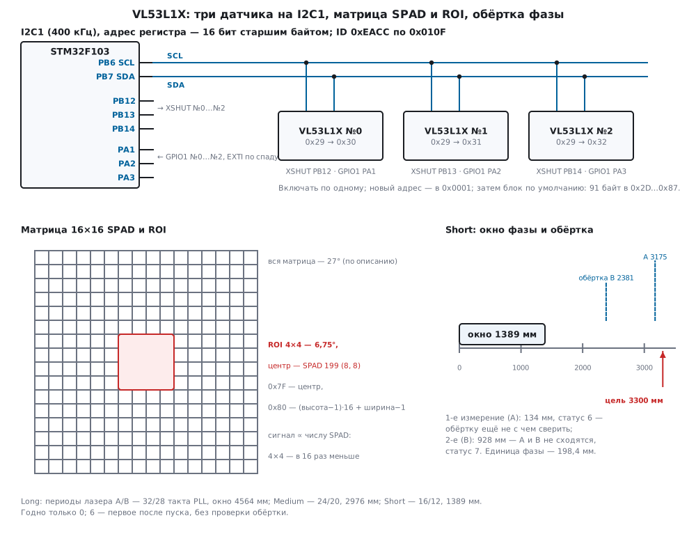
100г.2 Connection, 16-bit registers, the word 0xEACC and the 91-byte block
| Pin | What it is | Where in the firmware |
|---|---|---|
| SCL, SDA | I²C, address 0x29 after power-up |
PB6, PB7 — I2C1, 400 kHz |
| XSHUT | reset and hardware standby, active low | PB12, PB13, PB14 — open drain |
| GPIO1 | "ready" or "window hit"; the polarity is set by register 0x30 |
PA1, PA2, PA3 — EXTI on the falling edge |
| supply, ground | per the module description | — |
The bus is the same as for the L0X, and so is the I2C1 code in the firmware (100б, full sources below). The difference is the register address: two bytes, high byte first. Multi-byte register data is high byte first too.
int l1_wr(l1_t *d, uint16_t reg, const uint8_t *p, uint32_t n)
{
    uint8_t b[2u + L1_MAX_WR];
    if (n > L1_MAX_WR)
        return 1;
    b[0] = (uint8_t)(reg >> 8);
    b[1] = (uint8_t)reg;
    memcpy(b + 2, p, n);
    d->xfers++;
    d->bytes += n + 2u;
    return l1_i2c_write(d->addr, b, n + 2u);
}
int l1_rd(l1_t *d, uint16_t reg, uint8_t *p, uint32_t n)
{
    uint8_t a[2] = {(uint8_t)(reg >> 8), (uint8_t)reg};
    d->xfers++;
    d->bytes += n + 2u;
    return l1_i2c_wr_rd(d->addr, a, 2, p, n);
}
Swapping the address bytes is easy: reading the "ID word" with the address sent low byte first
goes to register 0x0F01, and the model returned 0x0000 — not an error, just zeros. That is
why the ID word is the first check after power-up.
The word 0xEACC. These are two consecutive bytes: 0xEA at 0x010F — the model number (the
default value in the API register map) — and 0xCC at 0x0110 — the module type (in the API:
"VL53L1 = 0xCC, VL53L3 = 0xAA"). We read it as a word and compare with 0xEACC, as the OpenMV
library does.
Boot. After XSHUT is released the sensor loads its firmware; the Zephyr driver allows "up to
1.2 ms" for it, and the API waits for bit 0 of register 0xE5. Our driver polls that bit every
200 µs; while the sensor boots it does not answer, and that also means "not ready yet".
/* Отпустить XSHUT, дождаться загрузки (бит 0 регистра 0xE5), проверить слово 0xEACC и перевести датчик на свой
 * адрес. Пока датчик грузится, он не отвечает — это тоже «ещё не готов». */
int l1_boot(l1_t *d, uint8_t idx, uint8_t addr7)
{
    uint8_t st = 0;
    uint16_t id = 0;
    uint32_t k;
    memset(d, 0, sizeof *d);
    d->idx = idx;
    d->addr = L1_ADDR_DEFAULT;
    l1_xshut(idx, 1);
    for (k = 0; k < L1_BOOT_TRIES; k++) {
        l1_delay_us(L1_BOOT_POLL_US);
        if (l1_rd(d, L1_FW_STATUS, &st, 1) == 0 && (st & 1u))
            break;
    }
    if (k == L1_BOOT_TRIES)
        return 1;
    if (l1_rd16(d, L1_MODEL_ID, &id) || id != L1_ID)
        return 2;
    if (addr7 != L1_ADDR_DEFAULT) {
        if (l1_wr8(d, L1_I2C_ADDR, addr7))          /* семибитный адрес; API делит 8-битный на 2 сам */
            return 3;
        d->addr = addr7;
        id = 0;
        if (l1_rd16(d, L1_MODEL_ID, &id) || id != L1_ID)
            return 4;
    }
    return 0;
}
In the model boot takes 1.2 ms: the first acknowledge came 1337.5 µs after XSHUT, on access number 7; the whole bring-up of one sensor is 7 transactions, 22 bytes, 400 µs of bus time.
The 91-byte block. As with the L0X, there is no public register description of the VL53L1X;
the ST API loads settings from presets, and the light ULD driver — with one write of a ready block
to registers 0x2D…0x87: 0x87 − 0x2D + 1 = 91 bytes. The block is in the OpenMV library; its
comments refer to ULD functions — VL53L1X_init(), SetROI(), StartRanging() — so that is
where it comes from (per the manufacturer's documentation, not verified). What is in it, per the
comments and the API register map:
| Registers | In the block | What it is | In the API presets |
|---|---|---|---|
0x30 |
0x01 |
GPIO1: interrupt output, bit 4 = 0 — active high | 0x11 — active low |
0x46 |
0x20 |
interrupt on every new measurement | the same |
0x5E…0x63 |
0x01DB, 15, 0x01F1, 13 |
timeouts and laser periods A and B — Long mode | Long: 15 and 13 |
0x64 |
0x0168 |
sigma limit, 14.2: 90 mm | 360 → 90 mm |
0x66 |
0x0080 |
signal limit, 9.7: 1.0 MCPS | 192 → 1.5 MCPS |
0x69 |
0xB8 |
top of the phase window, 5.3: 23.0 | Long: 0xB8 |
0x6C |
0x00000F89 |
timed period | set separately |
0x7F, 0x80 |
0xC7, 0xFF |
ROI centre — SPAD 199, size 16×16 | the same |
0x81 |
0x9B |
measurement steps: no MM2 | 0xDB — with MM2 |
0x86, 0x87 |
0x01, 0x40 |
clear the interrupt; start timed ranging | — |
The last byte is a trap: with 0x40 in 0x87 measurements would start right when the block is
loaded. Ours has 0x00 there and starts separately. At frequency 0xBCCC the block timeouts are
42857 and 41259 µs, i.e. a budget of about 43 ms. After the block we do what the API and
OpenMV do: the offset from 0x22 × 4 into 0x1E (the MM steps are off, only this one works),
then the polarity and the oscillator frequencies.
/* Загрузить блок по умолчанию одной записью, перенести заводское смещение, сделать GPIO1 активным нулём,
 * прочитать частоты генераторов. После этого — режим Long, бюджет 33 мс, ROI 16×16. */
int l1_init(l1_t *d)
{
    uint16_t v = 0;
    if (l1_wr(d, L1_CFG_FIRST, L1_DEFAULT_CFG, L1_CFG_LEN))
        return 10;
    if (l1_rd16(d, L1_OUTER_OFFSET_MM, &v) || l1_wr16(d, L1_OFFSET_MM, (uint16_t)(v * 4u)))   /* как в OpenMV */
        return 11;
    if (l1_wr8(d, L1_GPIO_MUX, 0x11u))               /* в блоке 0x01 — активна единица; пресеты API: 0x11 */
        return 12;
    if (l1_rd16(d, L1_OSC_FREQ, &d->osc) || d->osc == 0)
        return 13;
    if (l1_rd16(d, L1_OSC_CAL, &v))
        return 14;
    d->osc_cal = v & 0x3FFu;
    d->budget_us = 33000u;
    if (l1_set_mode(d, L1_LONG))
        return 15;
    return 0;
}
Bring-up by the block is 13 transactions, 138 bytes, 3537.5 µs of bus time; 2120 µs of it is the single block write.
Three sensors on one bus are brought up as the L0X in 100б.5: all XSHUT low, then one by one —
release, wait for boot, check the ID at 0x29, write the new address. One difference: the
address lives in register 0x0001, and a seven-bit address goes there — the API function
VL53L1_SetDeviceAddress divides the eight-bit address it is given by 2 itself, as with the L0X. On
the bench three sensors got 0x30, 0x31, 0x32 in 27 transactions, 1912.5 µs of bus
time and 5512.5 µs with boot. Released all at once — all three moved to 0x30.
Sleep and supply. The Zephyr binding describes XSHUT so: low is hardware standby with the
supply present, or full power-off without it. After standby the address is 0x29 again and the
block must be loaded again. Between timed measurements the sensor idles by itself; with a 33 ms
budget and a 100 ms period it measures a third of the time. Currents in each state and the module
supply are per the manufacturer's documentation, not verified; the model does not compute them.
100г.3 Short, Medium, Long; the budget and the timed period
A mode is a pair of laser periods for timings A and B plus the top of the phase window. The
numbers come from the API presets standard_ranging_short_range, standard_ranging and
standard_ranging_long_range; the window and the wrap in millimetres are recomputed with 198.4
mm per phase unit.
| Mode | Period A / B, PLL clocks | A / B, ns | Phase window | Window, mm | Wrap A / B, mm | Zephyr table: dark / bright |
|---|---|---|---|---|---|---|
| Short | 16 / 12 | 21.19 / 15.89 | 7.0 | 1389 | 3175 / 2381 | 136 / 135 cm |
| Medium | 24 / 20 | 31.78 / 26.48 | 15.0 | 2976 | 4762 / 3968 | 290 / 76 cm |
| Long | 32 / 28 | 42.37 / 37.08 | 23.0 | 4564 | 6349 / 5556 | 360 / 73 cm |
The API comments on the presets name windows of 1.4, 3.0 and 4.6 m — this matches the recomputation. The right-hand table is quoted in the Zephyr driver from the sensor description (not verified): in the dark Short and Medium hit their window, Long hits the signal.
/* Режимы — как пресеты API standard_ranging_short_range / standard_ranging / _long_range: периоды лазера A и B,
 * верх окна фазы, окна и начальные фазы сигма-дельты. После смены периода таймауты пересчитываются. */
int l1_set_mode(l1_t *d, l1_dist_t m)
{
    static const uint8_t va[3] = {0x07u, 0x0Bu, 0x0Fu}, vb[3] = {0x05u, 0x09u, 0x0Du};
    static const uint8_t ph[3] = {0x38u, 0x78u, 0xB8u}, ip[3] = {6u, 10u, 14u};
    uint8_t b[4];
    if (m < L1_SHORT || m > L1_LONG)
        return 1;
    d->vcsel_a = va[m - 1];
    d->vcsel_b = vb[m - 1];
    if (l1_wr8(d, L1_VCSEL_A, d->vcsel_a) || l1_wr8(d, L1_VCSEL_B, d->vcsel_b) || l1_wr8(d, L1_PHASE_HIGH, ph[m - 1]))
        return 2;
    b[0] = d->vcsel_a;
    b[1] = d->vcsel_b;
    b[2] = ip[m - 1];
    b[3] = ip[m - 1];
    if (l1_wr(d, L1_WOI_SD0, b, 4))                     /* 0x78…0x7B одной записью */
        return 3;
    return put_timeouts(d) ? 4 : 0;
}
The budget into registers. The sensor counts time in macro periods: 2304 laser periods (an ambient window of 256 and a ranging window of 2048). In Long the timing-A macro period is 97.625 µs, B is 85.421 µs. A timeout is written in the format "(low byte shifted left by the high byte) + 1". For a mode without MM steps the API subtracts a 1000 µs guard from the budget and writes the rest to both timings; we do the same.
/* ── время: те же формулы, что VL53L1_calc_macro_period_us и VL53L1_calc_encoded_timeout в API ── */
uint32_t l1_macro_q12(uint16_t osc, uint8_t vcsel_code)
{
    uint32_t pll = (1u << 30) / osc;                    /* период PLL, мкс, 0.24 */
    uint32_t m = (2304u * pll) >> 6;                    /* макропериод — 2304 периода лазера */
    m *= (uint32_t)((vcsel_code + 1u) << 1);            /* период лазера в тактах PLL */
    return m >> 6;                                      /* мкс, 12.12 */
}

uint16_t l1_encode_timeout(uint32_t us, uint32_t macro_q12)
{
    uint32_t mclks = ((us << 12) + (macro_q12 >> 1)) / macro_q12;
    uint32_t ls;
    uint16_t ms = 0;
    if (mclks == 0)
        return 0;
    ls = mclks - 1u;                                    /* формат (LSB << MSB) + 1 */
    while (ls & 0xFFFFFF00u) {
        ls >>= 1;
        ms++;
    }
    return (uint16_t)((ms << 8) | (ls & 0xFFu));
}
What came out in Long (frequency 0xBCCC):
| Budget, ms | 0x5E (A) |
0x61 (B) |
Timeout A, µs | Timeout B, µs |
|---|---|---|---|---|
| 15 | 0x008E |
0x00A3 |
13960 | 14009 |
| 20 | 0x00C2 |
0x00DD |
19037 | 18964 |
| 33 | 0x01A3 |
0x01BB |
31923 | 32033 |
| 50 | 0x01FA |
0x028F |
48910 | 48946 |
| 100 | 0x02FD |
0x0390 |
98894 | 98491 |
| 200 | 0x03FE |
0x0491 |
198471 | 198263 |
| 500 | 0x059F |
0x05B6 |
496811 | 497580 |
Phase calibration is 1000 µs as in the presets: 0x4B gets 10 macro periods in Long,
14 in Medium, 20 in Short. All 21 code pairs (three modes, seven budgets) and the SPAD
numbers for all 256 cells were checked by the bench against API functions taken verbatim
(VL53L1_calc_macro_period_us, VL53L1_calc_encoded_timeout, VL53L1_encode_row_col): 21 of 21
and 256 of 256 matched. Our driver rejects budgets of 14 and 501 ms — the ULD limits. The API
would allow more: up to 550000 µs left after the guard.
Back-to-back and timed. 0x20 in 0x87 — measurements back to back, 0x40 — timed, 0x10 —
a single one. In the model back-to-back measurements came every 33498 and 33608 µs at a 33 ms budget
(timings A and B differ slightly), at 20 and 100 ms — 20539 / 20612 and 100066 / 100469 µs. The timed
period is milliseconds × the number of slow-oscillator ticks per millisecond from 0xDE (bits
9:0), as VL53L1_set_inter_measurement_period_ms does. The API requires the period to be at least
the budget + 4 ms; so does our driver: 36 ms at a 33 ms budget is rejected.
/* Период по таймеру: миллисекунды × тики медленного генератора (VL53L1_set_inter_measurement_period_ms). */
int l1_set_imp(l1_t *d, uint32_t ms)
{
    if (ms < d->budget_us / 1000u + L1_IMP_GUARD_MS)
        return 1;
    return l1_wr32(d, L1_IMP, ms * d->osc_cal) ? 2 : 0;
}
In the model the oscillator gives 40 ticks per millisecond (an assumption), and 100 ms was written
as 0x00000FA0; results came every 99890 and 100110 µs.
100г.4 Noise and range: what the budget and the mode give (model)
The API does not reveal how the sensor computes sigma: it arrives ready in register 0x92. So
the model's noise is our own formula: σ = c · 8 ns / 2 · √(Ns + W·Na) / Ns, where Ns and Na are the
signal and ambient counts over the timeout, 8 ns is the pulse width from the API settings, W is
the laser period over 16 ns (the ambient window width from the same place). A white target at
3600 mm gives exactly 1.0 MCPS on the whole array — so the model is fitted to the 360 cm of the
table; the signal falls as 1/d², and a shorter laser period means more pulses and more signal.
Above 20 MCPS the sensor switches part of the SPADs off (the DSS target from the presets). These
are assumptions, not the sensor.
100 measurements per point, the spread of valid ones and the mean sigma the "sensor" puts into
0x92:
| Budget | Long, white 1 m | Long, grey 0.2 at 1.2 m | Short, grey 0.2 at 1.2 m |
|---|---|---|---|
| 15 ms | 2.65 (2.75) | 8.48 (7.25) | 4.44 (5.00) |
| 20 ms | 2.05 (2.38) | 6.49 (6.25) | 3.98 (4.25) |
| 33 ms | 1.88 (1.75) | 4.68 (4.88) | 3.16 (3.25) |
| 50 ms | 1.28 (1.50) | 3.71 (3.88) | 2.84 (2.62) |
| 100 ms | 1.01 (1.00) | 2.92 (2.75) | 1.95 (1.88) |
| 200 ms | 0.69 (0.75) | 1.81 (2.00) | 1.33 (1.38) |
| 500 ms | 0.53 (0.50) | 1.21 (1.25) | 0.95 (0.88) |
Four times the time — roughly half the spread, as with the L0X. Each hundred has 99 valid: the first measurement after start arrives with status 6 (100г.5).
The range of a white target — the largest where at least 90 % of 40 measurements are valid and within 100 mm of the truth (33 ms budget):
| Mode | Model: dark | Table: dark | Model: bright light | Table: bright |
|---|---|---|---|---|
| Short | 1350 mm | 136 cm | 1190 mm | 135 cm |
| Medium | 2950 mm | 290 cm | 870 mm | 76 cm |
| Long | 3600 mm | 360 cm | 690 mm | 73 cm |
In the dark Short and Medium are stopped by the phase window in the model — that is not fitting but a recomputation from the presets, and it landed close to the table. Bright light in the model is 0.9 MCPS of ambient per SPAD, chosen so that Long ends near 73 cm; Short in the same light holds 1190 mm, Medium 870. The order is the same as in the table, the Medium numbers differ — the model is coarser than the sensor. The practical conclusion comes from the table, not from the model: in sunlight Long reaches no farther than Short.
100г.5 The range status and phase wraparound
The result is 17 bytes from 0x89: the sensor code (bits 4:0), report, measurement counter,
number of SPADs (8.8), signal and ambient (9.7, MCPS), sigma (14.2, mm), phase (5.11), range in
millimetres and the signal after the glass crosstalk is subtracted. The sensor code is turned into
a status by the API rules (SetSimpleData and ConvertStatusLite):
| Sensor code | API status | Meaning | What to do |
|---|---|---|---|
| 9 | 0 | valid | take it |
| 9 with counter 0 | 6 | valid, but the wrap was not checked | do not take: nothing to compare with |
| 6 | 1 | sigma above the limit | drop |
| 4 | 2 | weak signal, no target | "nothing seen" |
| 5 | 4 | phase out of the window | target beyond the window: a longer mode |
| 7 | 7 | phases A and B disagree — wrap | drop, change mode |
| 8 | 3 | clipped by the minimum range | per the task |
| 12 | 9 | signal not above the glass crosstalk | calibrate the glass |
| 1, 2, 3, 17 | 5 | hardware failure | restart |
/* Код датчика → статус API (SetSimpleData и ConvertStatusLite): первое измерение после пуска (счётчик 0)
 * обёртку фазы не проверяло — статус 6, а не 0. */
static uint8_t api_status(uint8_t raw, uint8_t stream)
{
    switch (raw) {
    case 1: case 2: case 3: case 17: return 5;      /* аппаратный сбой */
    case 13: return 13;                             /* ROI вне матрицы */
    case 18: return 10;                             /* синхронизация */
    case 9: return stream == 0 ? 6 : 0;             /* годно; без проверки обёртки — 6 */
    case 6: return 1;                               /* σ выше предела */
    case 4: return 2;                               /* сигнал слабый */
    case 8: return 3;                               /* обрезано по минимальной дальности */
    case 5: return 4;                               /* фаза вне окна */
    case 7: return 7;                               /* фазы A и B не сходятся — обёртка */
    case 12: return 9;                              /* сигнал не выше помехи стекла */
    default: return 255;
    }
}
The API also fixes negative ranges: down to −30 mm becomes zero, below — status 14. The API
correction factor (2011/2048, LITE_RANGING_GAIN_FACTOR) we do not apply, like OpenMV — which way
is right for a live sensor is not verified.
The model, 50 measurements in a row:
| Scene | Mode | Statuses | First ranges, mm |
|---|---|---|---|
| empty | Long | 2 — all | 166, 192, 700, 835 |
| white at 5000 mm | Long | 2 — all | 5014, 5001, 5012, 5009 |
| white at 2000 mm | Short | 4 — all | 2004, 2009, 2011, 2009 |
| white at 3300 mm | Short | 6 — the first, 7 — the rest | 134, 928, 139, 927 |
| reflectance 3.0 (three times whiter than white) at 5000 mm | Medium | 6 — the first, 7 — the rest | 238, 1035, 244, 1041 |
Phase wraparound is the main trap of the L1X. A white wall at 3300 mm in Short: that is beyond the timing-A wrap (3175 mm), and the first measurement showed 134 mm. There was nothing to compare it with — counter 0 — and code 9 became status 6, not 0. The second measurement (timing B, wrap at 2381 mm) gave 928 mm, the phases disagreed — status 7, and so on to the end. A filter that takes only status 0 does not let this error through; a filter "all but obvious failures" will pass 134 mm instead of 3.3 m. Bright far targets beyond the window are dangerous precisely because they have enough signal.
100г.6 Region of interest, window interrupt, glass and calibrations
ROI. The centre is the SPAD number in 0x7F, the size is in 0x80: the high nibble is height
− 1, the low one width − 1. SPADs are numbered not row by row but by the
VL53L1_encode_row_col rule; by default the centre is SPAD 199, cell (8, 8). The API does not
accept a region narrower than 4 SPADs (width − 1 below 3).
/* ── ROI: номер SPAD центра — как VL53L1_encode_row_col (y — строка, x — столбец) ── */
uint8_t l1_spad(uint8_t x, uint8_t y)
{
    if (y > 7u)
        return (uint8_t)(128u + (x << 3) + (15u - y));
    return (uint8_t)(((15u - x) << 3) + y);
}

/* Прямоугольник w×h SPAD с левым нижним углом (x0, y0); центр — как в VL53L1_SetUserROI. */
int l1_set_roi(l1_t *d, uint8_t x0, uint8_t y0, uint8_t w, uint8_t h)
{
    uint8_t b[2];
    if (w < 4u || h < 4u || x0 + w > 16u || y0 + h > 16u)
        return 1;
    b[0] = l1_spad((uint8_t)(x0 + w / 2u), (uint8_t)(y0 + h / 2u));
    b[1] = (uint8_t)(((h - 1u) << 4) | (w - 1u));
    return l1_wr(d, L1_ROI_CENTRE, b, 2) ? 2 : 0;       /* 0x7F и 0x80 подряд */
}
A narrow region means a narrow view and less signal. The model (the field of view is split evenly, 27° per the description — not verified), a wall at 1500 mm and a 4×4-SPAD box at 600 mm in the centre:
| ROI | Angle | SPAD | Signal at 1 m, MCPS | White range | Box: shown |
|---|---|---|---|---|---|
| 16×16 | 27° | 256 | 13.89 | 3600 mm | 1245 mm |
| 8×8 | 13.5° | 64 | 3.47 | 1800 mm | 902 mm |
| 4×4 | 6.75° | 16 | 0.87 | 900 mm | 610 mm |
The whole array sees the box and the wall at once and shows a signal-weighted mean — 1245 mm, which is neither of them. The 4×4 region sees the box (610 mm with the model's own +9 mm offset), but the white wall only to 900 mm: the signal is 16 times weaker.
"Scanning". Sixteen 4×4 regions in turn give a coarse 4×4 picture. We write the next ROI while the sensor waits for the interrupt to be cleared — the new measurement starts with it.
/* «Сканирование» 16 зонами 4×4 SPAD, построчно сверху вниз: ROI следующей зоны пишется, пока датчик ждёт
 * снятия прерывания, — следующее измерение начнётся уже с ней. */
int l1_scan(l1_t *d, int16_t mm[16], uint8_t st[16])
{
    l1_meas_t m;
    if (l1_set_roi(d, 0, 12, 4, 4) || l1_start(d, 0x20u))
        return 1;
    for (uint8_t z = 0; z < 16u; z++) {
        uint8_t n = (uint8_t)((z + 1u) & 15u);
        if (wait_irq(d) || l1_read(d, &m))
            return 2;
        mm[z] = m.mm;
        st[z] = m.status;
        if (l1_set_roi(d, (uint8_t)(4u * (n & 3u)), (uint8_t)(12u - 4u * (n >> 2)), 4, 4) || l1_clear(d))
            return 3;
    }
    return l1_stop(d) ? 4 : 0;
}
A wall at 800 mm, a box at 400 mm in the top-left quarter, Short, 33 ms (range / status):
| column 0 | 1 | 2 | 3 | |
|---|---|---|---|---|
| row 0 | 412 / 6 | 409 / 0 | 810 / 0 | 813 / 0 |
| row 1 | 409 / 0 | 408 / 0 | 811 / 0 | 808 / 0 |
| row 2 | 811 / 0 | 814 / 0 | 802 / 0 | 807 / 0 |
| row 3 | 808 / 0 | 805 / 0 | 806 / 0 | 809 / 0 |
One frame is 538.1 ms, 51 transactions. The first zone came with status 6 — the first measurement after start. In the model the wrap check compares only measurements with the same ROI; how a live sensor compares phases when the ROI changes on the fly is not verified.
Window interrupt. Register 0x46: bits 1:0 are the condition (0 — below the low threshold,
1 — above the high one, 2 — out of window, 3 — inside), bit 5 — "on every measurement"; the
thresholds in millimetres are 0x72 (high) and 0x74 (low).
/* Прерывание по окну дальности или на каждое измерение. Пороги — в 0x72 (верхний) и 0x74 (нижний). */
int l1_set_window(l1_t *d, l1_win_t win, uint16_t low_mm, uint16_t high_mm)
{
    uint8_t b[4] = {(uint8_t)(high_mm >> 8), (uint8_t)high_mm, (uint8_t)(low_mm >> 8), (uint8_t)low_mm};
    if (win != L1_EVERY && l1_wr(d, L1_THRESH_HIGH, b, 4))
        return 1;
    return l1_wr8(d, L1_INT_CONFIG, (uint8_t)win) ? 2 : 0;
}
A person approaches from 1500 to 300 mm in 5 s and walks back, a timed measurement every 100 ms, 10.4 s:
| Interrupt | Interrupts | Transactions | Bus, µs |
|---|---|---|---|
| on every measurement | 104 | 208 | 59800 |
| below 500 mm | 15 | 30 | 8625 |
| inside 400…700 mm | 26 | 52 | 14950 |
The processor sleeps while nothing happens; with the "below 500 mm" window the bus is busy 6.9 times less. The condition is checked on every measurement: while the person is inside the window, the interrupt comes every 100 ms, not once on entry.
Glass. The cover reflects part of the pulse into the receiver; the sensor mixes this reflection with the target, and the range is pulled toward zero — the more, the weaker the target. In the model the glass is 0.01 MCPS per SPAD. Two calibrations after the API:
- Offset (
VL53L1_PerformOffsetSimpleCalibration): a target at a known distance, drop the first measurement, average 50 valid ones; correction = distance − mean. We write it to0x22and, × 4, to0x1E. - Glass crosstalk (
SingleTargetXTalkCalibration): a target at 600 mm (the API default), 50 measurements without compensation; crosstalk per SPAD = signal / number of SPADs × (1 − measured / 600).0x16gets kilo-counts in format 7.9.
/* Калибровка помехи стекла — как SingleTargetXTalkCalibration в API: мишень на известной дальности, n измерений
 * без компенсации; помеха на SPAD = сигнал / SPAD · (1 − измерено / мишень). В 0x16 — кило-отсчёты в 7.9. */
int l1_cal_xtalk(l1_t *d, uint16_t target_mm, uint8_t n, uint16_t *kcps)
{
    uint32_t sum_mm = 0, sum_sig = 0, sum_sp = 0, got = 0, sig, sp, mm;
    l1_meas_t m;
    if (l1_wr16(d, L1_XTALK_KCPS, 0) || l1_wr32(d, L1_XTALK_X_GRAD, 0))
        return 1;
    if (l1_start(d, 0x20u) || wait_irq(d) || l1_clear(d))   /* первое измерение не в счёт */
        return 2;
    for (uint8_t i = 0; i < n; i++) {
        if (wait_irq(d) || l1_read(d, &m) || l1_clear(d))
            return 3;
        if (m.status == 0 && m.mm > 0) {
            sum_mm += (uint32_t)m.mm;
            sum_sig += m.signal;
            sum_sp += m.spads >> 8;
            got++;
        }
    }
    l1_stop(d);
    if (!got)
        return 4;
    sig = sum_sig / got;
    sp = (sum_sp + got / 2u) / got;
    mm = (sum_mm + got / 2u) / got;
    *kcps = 0;
    if (sp && mm < target_mm)                           /* MCPS 9.7 → кило-отсчёты 7.9: · 1000 · 512 / 128 */
        *kcps = (uint16_t)((sig * 4000u / sp) * (target_mm - mm) / target_mm);
    return l1_wr16(d, L1_XTALK_KCPS, *kcps) ? 5 : 0;
}
Mean error of valid ones, mm (30 measurements each, Long, 33 ms):
| 150 mm | 300 mm | 600 mm | 1000 mm | 2000 mm | no target | |
|---|---|---|---|---|---|---|
| no calibration | +9 | +4 | −28 | −147 | all status 7 | status 0 |
| after the offset | 0 | −5 | −38 | −156 | all status 7 | status 0 |
| after the crosstalk | 0 | −1 | 0 | −3 | −20 | status 2 |
The offset calibration at 100 mm found −9 mm — the model's own offset — in 108 transactions and 1711.5 ms. The glass calibration found 0.00987 MCPS per SPAD against the 0.01 set (code 5051) in 1711.3 ms. Without it a far target reads hundreds of millimetres short, at 2000 mm timings A and B disagree and every measurement is status 7, and with no target the sensor "sees" the glass a few millimetres away with status 0. After it — status 2 with no target, as it should be. The order is the offset first, then the glass, with the glass in place.
100г.7 Pitfalls
The interrupt came once, no new data. The interrupt was not cleared by writing 0x01 to
0x86. In the model the next measurement waits for the clear: in a second — one interrupt, counter
0, GPIO1 stuck low; after the clear the counter went 1…5.
The ID reads as 0x0000. The register address was sent low byte first — it went to 0x0F01.
Two address bytes, high byte first.
A wall at 3.3 m shown as 134 mm. Phase wrap in Short, and the filter took status 6. Only 0 is valid; for far bright targets — Medium or Long.
In sunlight Long sees worse than Short. By the table from the description — 73 cm against 135; in the model — 690 against 1190 mm. In light — Short.
Through glass the range reads short, and with no target the sensor "sees" something right at its nose. No glass crosstalk calibration. Offset, then crosstalk, with the glass in place.
GPIO1 gives no falling edge. The default block leaves 0x30 = 0x01 — active high; EXTI on
the falling edge with a pull-up expects active low. Write 0x11.
Measurements started by themselves right after the block was loaded. In the OpenMV block the
last byte is 0x40 in 0x87. Ours has 0x00.
The first measurement after start "is not valid". Status 6: the wrap was not checked. That is normal; the API calibrations drop it too.
The timed period will not set. Below the budget + 4 ms neither the API nor our driver accepts it.
A narrow ROI "does not see" the far wall. 4×4 SPADs — 16 times less signal: in the model a white wall up to 900 mm instead of 3600.
The second sensor is at someone else's address. XSHUT were released all at once — the write
to 0x0001 reached everyone.
100г.8 Summary
- The VL53L1X has the same address
0x29, XSHUT and GPIO1 as the L0X, but 16-bit register addresses, a 16×16 SPAD array with a region of interest and two timings A and B. The ID word is0xEACCat0x010F. - Our own register driver instead of the API: a 91-byte block into
0x2D…0x87, one sensor's bring-up is 13 transactions; in the three-sensor firmware the driver is 1714 bytes of code, the whole image 3192 bytes of code, 3536 of flash and 84 bytes of RAM (the L0X with its library — 12988 bytes of code). - One phase unit is 198.4 mm; the Short, Medium, Long windows are 1389, 2976 and 4564 mm, the timing-A wrap in Short is 3175 mm.
- Budget − 1000 µs goes into timeouts A and B; the codes matched the API functions in all 21 cases. The timed period is at least the budget + 4 ms.
- Spread in the model: Long, white at 1 m — 2.65 mm in 15 ms and 0.53 mm in 500 ms.
- Only 0 is valid. Status 6 — the first after start, 7 — wrap, 4 — target beyond the window, 2 — no signal.
- ROI 4×4 — 6.75° and 16 times less signal; 16 zones give a 4×4 picture in 538.1 ms.
- A window interrupt instead of "every measurement": 15 interrupts instead of 104 in 10.4 s.
- Glass: offset calibration, then crosstalk — the error at 1000 mm goes from −147 to −3 mm in the model.
Full sources
The register driver and the three-sensor firmware. The bench host100e.c, the model
model100e.py, the API cross-check ref100e.c and the API function excerpt st_ref.c are in
_verify/tof100e/.
tof100e.h — registers, constants, the bus and the driver state.
/* Раздел 100г: VL53L1X прямо по регистрам — без библиотеки ST. Адреса регистров и форматы — из карты регистров
 * API ST VL53L1X 2.4.5 (vl53l1_register_map.h, модуль hal_st Zephyr); блок настроек по умолчанию — из открытой
 * библиотеки vl53l1x (набор скриптов OpenMV), его комментарии ссылаются на функции ULD. Шину и выводы даёт
 * прошивка (fw100e.c — I2C1 STM32F103) или стенд (host100e.c — строки к модели model100e.py). */
#ifndef TOF100E_H
#define TOF100E_H
#include <stdint.h>

/* ── адреса регистров: 16 бит, на шину — старшим байтом вперёд ── */
#define L1_SOFT_RESET        0x0000u
#define L1_I2C_ADDR          0x0001u   /* [6:0] — семибитный адрес */
#define L1_OSC_FREQ          0x0006u   /* частота быстрого генератора, 4.12, МГц — из заводской памяти */
#define L1_XTALK_KCPS        0x0016u   /* помеха стекла на один SPAD, кило-отсчётов/с, 7.9 */
#define L1_XTALK_X_GRAD      0x0018u
#define L1_XTALK_Y_GRAD      0x001Au
#define L1_OFFSET_MM         0x001Eu   /* смещение дальности, мм, 11.2 */
#define L1_INNER_OFFSET_MM   0x0020u
#define L1_OUTER_OFFSET_MM   0x0022u
#define L1_GPIO_MUX          0x0030u   /* бит 4: 1 — GPIO1 активен нулём (так в пресетах API) */
#define L1_GPIO_STATUS       0x0031u   /* бит 0 — уровень GPIO1 */
#define L1_INT_CONFIG        0x0046u   /* [1:0] — окно по дальности, бит 5 — «новое измерение» */
#define L1_PHASECAL_TIMEOUT  0x004Bu
#define L1_TIMEOUT_A         0x005Eu   /* таймаут дальнометрии, тайминг A: (LSB << MSB) + 1 макропериодов */
#define L1_VCSEL_A           0x0060u   /* период лазера A: (код + 1) · 2 такта PLL */
#define L1_TIMEOUT_B         0x0061u
#define L1_VCSEL_B           0x0063u
#define L1_SIGMA_THRESH      0x0064u   /* предел σ, мм, 14.2 */
#define L1_MIN_RATE          0x0066u   /* предел сигнала, MCPS, 9.7 */
#define L1_PHASE_LOW         0x0068u   /* окно фазы, 5.3 */
#define L1_PHASE_HIGH        0x0069u
#define L1_IMP               0x006Cu   /* период между измерениями: мс · OSC_CAL, 32 бита */
#define L1_THRESH_HIGH       0x0072u   /* пороги прерывания по дальности, мм */
#define L1_THRESH_LOW        0x0074u
#define L1_WOI_SD0           0x0078u
#define L1_WOI_SD1           0x0079u
#define L1_INIT_PHASE_SD0    0x007Au
#define L1_INIT_PHASE_SD1    0x007Bu
#define L1_ROI_CENTRE        0x007Fu   /* номер SPAD центра ROI */
#define L1_ROI_SIZE          0x0080u   /* старшая тетрада — высота − 1, младшая — ширина − 1 */
#define L1_INT_CLEAR         0x0086u
#define L1_MODE_START        0x0087u   /* 0x10 — однократно, 0x20 — подряд, 0x40 — по таймеру, 0 — стоп */
#define L1_RESULT            0x0089u   /* 17 байт: статус, отчёт, счётчик, SPAD, сигнал, фон, σ, фаза, дальность… */
#define L1_OSC_CAL           0x00DEu   /* [9:0] — тиков медленного генератора на миллисекунду */
#define L1_FW_STATUS         0x00E5u   /* бит 0 — прошивка датчика загрузилась */
#define L1_MODEL_ID          0x010Fu   /* слово 0xEACC: модель 0xEA и тип модуля 0xCC */

#define L1_ADDR_DEFAULT  0x29u
#define L1_ID            0xEACCu
#define L1_CFG_FIRST     0x002Du   /* блок по умолчанию: 0x2D…0x87 */
#define L1_CFG_LEN       91u
#define L1_BOOT_POLL_US  200u      /* опрос загрузки — наше значение */
#define L1_BOOT_TRIES    20u
#define L1_GUARD_US      1000u     /* запас API для LITE без MM1/MM2: бюджет − 1000 мкс = таймаут дальнометрии */
#define L1_TB_MIN_MS     15u       /* пределы бюджета по ULD — по документации производителя, не проверено */
#define L1_TB_MAX_MS     500u
#define L1_IMP_GUARD_MS  4u        /* API: период по таймеру не меньше бюджета + 4 мс */
#define L1_PHASECAL_US   1000u     /* таймаут калибровки фазы в пресетах API */

/* ── шина и выводы: реализует прошивка или стенд ── */
int  l1_i2c_write(uint8_t addr7, const uint8_t *buf, uint32_t n);                    /* 0 — всё подтверждено */
int  l1_i2c_wr_rd(uint8_t addr7, const uint8_t *wr, uint32_t nw, uint8_t *rd, uint32_t nr);
void l1_delay_us(uint32_t us);
void l1_xshut(uint8_t idx, int run);   /* run = 1 — отпустить XSHUT, 0 — прижать к земле */
int  l1_idle(void);                    /* ждать прерывания: прошивка — WFI, стенд — до фронта GPIO1; 0 — не дождались */

typedef enum { L1_SHORT = 1, L1_MEDIUM = 2, L1_LONG = 3 } l1_dist_t;      /* нумерация как у API и Zephyr */
typedef enum { L1_BELOW = 0, L1_ABOVE = 1, L1_OUTSIDE = 2, L1_INSIDE = 3, L1_EVERY = 0x20 } l1_win_t;

typedef struct {
    int16_t mm;             /* дальность из 0x96 — без поправочного множителя API */
    uint8_t raw;            /* код датчика, биты 4:0 байта 0x89 */
    uint8_t status;         /* статус по правилам API: 0 годно, 1 σ, 2 сигнал, 4 вне окна, 6 без проверки обёртки… */
    uint8_t stream;         /* счётчик измерений 0x8B */
    uint16_t signal;        /* MCPS, 9.7 */
    uint16_t ambient;       /* MCPS, 9.7 */
    uint16_t sigma;         /* мм, 14.2 */
    uint16_t spads;         /* число SPAD, 8.8 */
} l1_meas_t;

typedef struct {
    uint8_t addr;           /* адрес на шине, 7 бит */
    uint8_t idx;            /* номер вывода XSHUT и GPIO1 */
    uint16_t osc;           /* 0x0006: быстрый генератор, 4.12 */
    uint16_t osc_cal;       /* 0x00DE & 0x3FF */
    uint8_t vcsel_a, vcsel_b;
    uint32_t budget_us;
    volatile uint8_t irq;   /* GPIO1 сработал — ставит обработчик EXTI */
    uint32_t xfers, bytes;  /* транзакции и байты на шине */
} l1_t;

extern const uint8_t L1_DEFAULT_CFG[L1_CFG_LEN];

int  l1_rd(l1_t *d, uint16_t reg, uint8_t *p, uint32_t n);
int  l1_wr(l1_t *d, uint16_t reg, const uint8_t *p, uint32_t n);
int  l1_rd16(l1_t *d, uint16_t reg, uint16_t *v);
int  l1_wr8(l1_t *d, uint16_t reg, uint8_t v);
int  l1_wr16(l1_t *d, uint16_t reg, uint16_t v);
int  l1_wr32(l1_t *d, uint16_t reg, uint32_t v);
void l1_sleep_all(uint8_t n);
int  l1_boot(l1_t *d, uint8_t idx, uint8_t addr7);
int  l1_init(l1_t *d);
uint32_t l1_macro_q12(uint16_t osc, uint8_t vcsel_code);
uint16_t l1_encode_timeout(uint32_t us, uint32_t macro_q12);
int  l1_set_mode(l1_t *d, l1_dist_t m);
int  l1_set_budget(l1_t *d, uint32_t ms);
int  l1_set_imp(l1_t *d, uint32_t ms);
uint8_t l1_spad(uint8_t x, uint8_t y);
int  l1_set_roi(l1_t *d, uint8_t w, uint8_t h, uint8_t x, uint8_t y);
int  l1_set_window(l1_t *d, l1_win_t win, uint16_t low_mm, uint16_t high_mm);
int  l1_start(l1_t *d, uint8_t mode);
int  l1_stop(l1_t *d);
int  l1_clear(l1_t *d);
int  l1_read(l1_t *d, l1_meas_t *m);
int  l1_cal_offset(l1_t *d, uint16_t target_mm, uint8_t n, int16_t *ofs);
int  l1_cal_xtalk(l1_t *d, uint16_t target_mm, uint8_t n, uint16_t *kcps);
int  l1_scan(l1_t *d, int16_t mm[16], uint8_t st[16]);
#endif
tof100e.c — the driver: default block, power-up, modes and budget, ROI, window, statuses, calibrations, scanning.
/* Раздел 100г: драйвер VL53L1X по регистрам. Общий для прошивки и стенда. */
#include <string.h>
#include "tof100e.h"

/* Блок по умолчанию для 0x2D…0x87 — как в открытой библиотеке vl53l1x (OpenMV), кроме последнего байта:
 * там 0x40 (измерения стартуют сразу после загрузки), у нас 0x00 — стартуем сами. */
const uint8_t L1_DEFAULT_CFG[L1_CFG_LEN] = {
    0x00, 0x00, 0x00, 0x01, 0x02, 0x00, 0x02, 0x08, 0x00, 0x08, 0x10, 0x01, 0x01, 0x00, 0x00, 0x00, /* 0x2D */
    0x00, 0xFF, 0x00, 0x0F, 0x00, 0x00, 0x00, 0x00, 0x00, 0x20, 0x0B, 0x00, 0x00, 0x02, 0x0A, 0x21, /* 0x3D */
    0x00, 0x00, 0x05, 0x00, 0x00, 0x00, 0x00, 0xC8, 0x00, 0x00, 0x38, 0xFF, 0x01, 0x00, 0x08, 0x00, /* 0x4D */
    0x00, 0x01, 0xDB, 0x0F, 0x01, 0xF1, 0x0D, 0x01, 0x68, 0x00, 0x80, 0x08, 0xB8, 0x00, 0x00, 0x00, /* 0x5D */
    0x00, 0x0F, 0x89, 0x00, 0x00, 0x00, 0x00, 0x00, 0x00, 0x00, 0x01, 0x0F, 0x0D, 0x0E, 0x0E, 0x00, /* 0x6D */
    0x00, 0x02, 0xC7, 0xFF, 0x9B, 0x00, 0x00, 0x00, 0x01, 0x01, 0x00,                               /* 0x7D */
};

/* ── обращение к регистру: два байта адреса старшим вперёд, затем данные ── */
#define L1_MAX_WR 96u

int l1_wr(l1_t *d, uint16_t reg, const uint8_t *p, uint32_t n)
{
    uint8_t b[2u + L1_MAX_WR];
    if (n > L1_MAX_WR)
        return 1;
    b[0] = (uint8_t)(reg >> 8);
    b[1] = (uint8_t)reg;
    memcpy(b + 2, p, n);
    d->xfers++;
    d->bytes += n + 2u;
    return l1_i2c_write(d->addr, b, n + 2u);
}

int l1_rd(l1_t *d, uint16_t reg, uint8_t *p, uint32_t n)
{
    uint8_t a[2] = {(uint8_t)(reg >> 8), (uint8_t)reg};
    d->xfers++;
    d->bytes += n + 2u;
    return l1_i2c_wr_rd(d->addr, a, 2, p, n);
}

int l1_rd16(l1_t *d, uint16_t reg, uint16_t *v)
{
    uint8_t b[2] = {0, 0};
    int e = l1_rd(d, reg, b, 2);
    *v = (uint16_t)((b[0] << 8) | b[1]);             /* данные тоже старшим байтом вперёд */
    return e;
}

int l1_wr8(l1_t *d, uint16_t reg, uint8_t v)
{
    return l1_wr(d, reg, &v, 1);
}

int l1_wr16(l1_t *d, uint16_t reg, uint16_t v)
{
    uint8_t b[2] = {(uint8_t)(v >> 8), (uint8_t)v};
    return l1_wr(d, reg, b, 2);
}

int l1_wr32(l1_t *d, uint16_t reg, uint32_t v)
{
    uint8_t b[4] = {(uint8_t)(v >> 24), (uint8_t)(v >> 16), (uint8_t)(v >> 8), (uint8_t)v};
    return l1_wr(d, reg, b, 4);
}

/* ── включение по одному и смена адреса ── */
void l1_sleep_all(uint8_t n)
{
    for (uint8_t i = 0; i < n; i++)
        l1_xshut(i, 0);
    l1_delay_us(L1_BOOT_POLL_US);
}

/* Отпустить XSHUT, дождаться загрузки (бит 0 регистра 0xE5), проверить слово 0xEACC и перевести датчик на свой
 * адрес. Пока датчик грузится, он не отвечает — это тоже «ещё не готов». */
int l1_boot(l1_t *d, uint8_t idx, uint8_t addr7)
{
    uint8_t st = 0;
    uint16_t id = 0;
    uint32_t k;
    memset(d, 0, sizeof *d);
    d->idx = idx;
    d->addr = L1_ADDR_DEFAULT;
    l1_xshut(idx, 1);
    for (k = 0; k < L1_BOOT_TRIES; k++) {
        l1_delay_us(L1_BOOT_POLL_US);
        if (l1_rd(d, L1_FW_STATUS, &st, 1) == 0 && (st & 1u))
            break;
    }
    if (k == L1_BOOT_TRIES)
        return 1;
    if (l1_rd16(d, L1_MODEL_ID, &id) || id != L1_ID)
        return 2;
    if (addr7 != L1_ADDR_DEFAULT) {
        if (l1_wr8(d, L1_I2C_ADDR, addr7))          /* семибитный адрес; API делит 8-битный на 2 сам */
            return 3;
        d->addr = addr7;
        id = 0;
        if (l1_rd16(d, L1_MODEL_ID, &id) || id != L1_ID)
            return 4;
    }
    return 0;
}

/* Загрузить блок по умолчанию одной записью, перенести заводское смещение, сделать GPIO1 активным нулём,
 * прочитать частоты генераторов. После этого — режим Long, бюджет 33 мс, ROI 16×16. */
int l1_init(l1_t *d)
{
    uint16_t v = 0;
    if (l1_wr(d, L1_CFG_FIRST, L1_DEFAULT_CFG, L1_CFG_LEN))
        return 10;
    if (l1_rd16(d, L1_OUTER_OFFSET_MM, &v) || l1_wr16(d, L1_OFFSET_MM, (uint16_t)(v * 4u)))   /* как в OpenMV */
        return 11;
    if (l1_wr8(d, L1_GPIO_MUX, 0x11u))               /* в блоке 0x01 — активна единица; пресеты API: 0x11 */
        return 12;
    if (l1_rd16(d, L1_OSC_FREQ, &d->osc) || d->osc == 0)
        return 13;
    if (l1_rd16(d, L1_OSC_CAL, &v))
        return 14;
    d->osc_cal = v & 0x3FFu;
    d->budget_us = 33000u;
    if (l1_set_mode(d, L1_LONG))
        return 15;
    return 0;
}

/* ── время: те же формулы, что VL53L1_calc_macro_period_us и VL53L1_calc_encoded_timeout в API ── */
uint32_t l1_macro_q12(uint16_t osc, uint8_t vcsel_code)
{
    uint32_t pll = (1u << 30) / osc;                    /* период PLL, мкс, 0.24 */
    uint32_t m = (2304u * pll) >> 6;                    /* макропериод — 2304 периода лазера */
    m *= (uint32_t)((vcsel_code + 1u) << 1);            /* период лазера в тактах PLL */
    return m >> 6;                                      /* мкс, 12.12 */
}

uint16_t l1_encode_timeout(uint32_t us, uint32_t macro_q12)
{
    uint32_t mclks = ((us << 12) + (macro_q12 >> 1)) / macro_q12;
    uint32_t ls;
    uint16_t ms = 0;
    if (mclks == 0)
        return 0;
    ls = mclks - 1u;                                    /* формат (LSB << MSB) + 1 */
    while (ls & 0xFFFFFF00u) {
        ls >>= 1;
        ms++;
    }
    return (uint16_t)((ms << 8) | (ls & 0xFFu));
}

static int put_timeouts(l1_t *d)
{
    uint32_t r = d->budget_us - L1_GUARD_US;
    uint32_t pc = ((L1_PHASECAL_US << 12) + (l1_macro_q12(d->osc, d->vcsel_a) >> 1)) / l1_macro_q12(d->osc, d->vcsel_a);
    if (l1_wr8(d, L1_PHASECAL_TIMEOUT, (uint8_t)(pc > 0xFFu ? 0xFFu : pc)))
        return 1;
    if (l1_wr16(d, L1_TIMEOUT_A, l1_encode_timeout(r, l1_macro_q12(d->osc, d->vcsel_a))))
        return 1;
    return l1_wr16(d, L1_TIMEOUT_B, l1_encode_timeout(r, l1_macro_q12(d->osc, d->vcsel_b)));
}

/* Режимы — как пресеты API standard_ranging_short_range / standard_ranging / _long_range: периоды лазера A и B,
 * верх окна фазы, окна и начальные фазы сигма-дельты. После смены периода таймауты пересчитываются. */
int l1_set_mode(l1_t *d, l1_dist_t m)
{
    static const uint8_t va[3] = {0x07u, 0x0Bu, 0x0Fu}, vb[3] = {0x05u, 0x09u, 0x0Du};
    static const uint8_t ph[3] = {0x38u, 0x78u, 0xB8u}, ip[3] = {6u, 10u, 14u};
    uint8_t b[4];
    if (m < L1_SHORT || m > L1_LONG)
        return 1;
    d->vcsel_a = va[m - 1];
    d->vcsel_b = vb[m - 1];
    if (l1_wr8(d, L1_VCSEL_A, d->vcsel_a) || l1_wr8(d, L1_VCSEL_B, d->vcsel_b) || l1_wr8(d, L1_PHASE_HIGH, ph[m - 1]))
        return 2;
    b[0] = d->vcsel_a;
    b[1] = d->vcsel_b;
    b[2] = ip[m - 1];
    b[3] = ip[m - 1];
    if (l1_wr(d, L1_WOI_SD0, b, 4))                     /* 0x78…0x7B одной записью */
        return 3;
    return put_timeouts(d) ? 4 : 0;
}

int l1_set_budget(l1_t *d, uint32_t ms)
{
    if (ms < L1_TB_MIN_MS || ms > L1_TB_MAX_MS)
        return 1;
    d->budget_us = ms * 1000u;
    return put_timeouts(d) ? 2 : 0;
}

/* Период по таймеру: миллисекунды × тики медленного генератора (VL53L1_set_inter_measurement_period_ms). */
int l1_set_imp(l1_t *d, uint32_t ms)
{
    if (ms < d->budget_us / 1000u + L1_IMP_GUARD_MS)
        return 1;
    return l1_wr32(d, L1_IMP, ms * d->osc_cal) ? 2 : 0;
}

/* ── ROI: номер SPAD центра — как VL53L1_encode_row_col (y — строка, x — столбец) ── */
uint8_t l1_spad(uint8_t x, uint8_t y)
{
    if (y > 7u)
        return (uint8_t)(128u + (x << 3) + (15u - y));
    return (uint8_t)(((15u - x) << 3) + y);
}

/* Прямоугольник w×h SPAD с левым нижним углом (x0, y0); центр — как в VL53L1_SetUserROI. */
int l1_set_roi(l1_t *d, uint8_t x0, uint8_t y0, uint8_t w, uint8_t h)
{
    uint8_t b[2];
    if (w < 4u || h < 4u || x0 + w > 16u || y0 + h > 16u)
        return 1;
    b[0] = l1_spad((uint8_t)(x0 + w / 2u), (uint8_t)(y0 + h / 2u));
    b[1] = (uint8_t)(((h - 1u) << 4) | (w - 1u));
    return l1_wr(d, L1_ROI_CENTRE, b, 2) ? 2 : 0;       /* 0x7F и 0x80 подряд */
}

/* Прерывание по окну дальности или на каждое измерение. Пороги — в 0x72 (верхний) и 0x74 (нижний). */
int l1_set_window(l1_t *d, l1_win_t win, uint16_t low_mm, uint16_t high_mm)
{
    uint8_t b[4] = {(uint8_t)(high_mm >> 8), (uint8_t)high_mm, (uint8_t)(low_mm >> 8), (uint8_t)low_mm};
    if (win != L1_EVERY && l1_wr(d, L1_THRESH_HIGH, b, 4))
        return 1;
    return l1_wr8(d, L1_INT_CONFIG, (uint8_t)win) ? 2 : 0;
}

/* ── измерения ── */
static int wait_irq(l1_t *d)
{
    while (!d->irq)
        if (!l1_idle())
            return 1;
    d->irq = 0;
    return 0;
}

int l1_start(l1_t *d, uint8_t mode)
{
    uint8_t b[2] = {0x01u, mode};                       /* 0x86 — снять прерывание, 0x87 — пуск, одной записью */
    d->irq = 0;
    return l1_wr(d, L1_INT_CLEAR, b, 2);
}

int l1_stop(l1_t *d)
{
    return l1_wr8(d, L1_MODE_START, 0x80u);             /* ABORT — так останавливает API */
}

int l1_clear(l1_t *d)
{
    return l1_wr8(d, L1_INT_CLEAR, 0x01u);
}

/* Код датчика → статус API (SetSimpleData и ConvertStatusLite): первое измерение после пуска (счётчик 0)
 * обёртку фазы не проверяло — статус 6, а не 0. */
static uint8_t api_status(uint8_t raw, uint8_t stream)
{
    switch (raw) {
    case 1: case 2: case 3: case 17: return 5;      /* аппаратный сбой */
    case 13: return 13;                             /* ROI вне матрицы */
    case 18: return 10;                             /* синхронизация */
    case 9: return stream == 0 ? 6 : 0;             /* годно; без проверки обёртки — 6 */
    case 6: return 1;                               /* σ выше предела */
    case 4: return 2;                               /* сигнал слабый */
    case 8: return 3;                               /* обрезано по минимальной дальности */
    case 5: return 4;                               /* фаза вне окна */
    case 7: return 7;                               /* фазы A и B не сходятся — обёртка */
    case 12: return 9;                              /* сигнал не выше помехи стекла */
    default: return 255;
    }
}

int l1_read(l1_t *d, l1_meas_t *m)
{
    uint8_t r[17];
    if (l1_rd(d, L1_RESULT, r, sizeof r))
        return 1;
    m->raw = r[0] & 0x1Fu;
    m->stream = r[2];
    m->status = api_status(m->raw, m->stream);
    m->spads = (uint16_t)((r[3] << 8) | r[4]);
    m->ambient = (uint16_t)((r[7] << 8) | r[8]);
    m->sigma = (uint16_t)((r[9] << 8) | r[10]);
    m->mm = (int16_t)((r[13] << 8) | r[14]);
    m->signal = (uint16_t)((r[15] << 8) | r[16]);   /* сигнал после вычета помехи стекла */
    if (m->status == 0 && m->mm < -30)              /* как API: ниже −30 мм — недостоверно, до −30 — ноль */
        m->status = 14;
    else if (m->status == 0 && m->mm < 0)
        m->mm = 0;
    return 0;
}


/* Калибровка смещения — как VL53L1_PerformOffsetSimpleCalibration: мишень на известной дальности, первое
 * измерение выбросить, из годных взять среднее; смещение = дальность мишени − среднее. */
int l1_cal_offset(l1_t *d, uint16_t target_mm, uint8_t n, int16_t *ofs)
{
    int32_t sum = 0;
    uint32_t got = 0, tries = 0;
    l1_meas_t m;
    if (l1_wr16(d, L1_OFFSET_MM, 0) || l1_wr16(d, L1_INNER_OFFSET_MM, 0) || l1_wr16(d, L1_OUTER_OFFSET_MM, 0))
        return 1;
    if (l1_start(d, 0x20u) || wait_irq(d) || l1_clear(d))   /* первое прерывание — мимо */
        return 2;
    while (got < n && tries < n + n / 2u) {
        if (wait_irq(d) || l1_read(d, &m) || l1_clear(d))
            return 3;
        tries++;
        if (m.status == 0) {
            sum += m.mm;
            got++;
        }
    }
    l1_stop(d);
    if (got < 1u + n / 2u)
        return 4;
    *ofs = (int16_t)((int32_t)target_mm - (sum + (int32_t)got / 2) / (int32_t)got);
    if (l1_wr16(d, L1_OUTER_OFFSET_MM, (uint16_t)*ofs) || l1_wr16(d, L1_OFFSET_MM, (uint16_t)(*ofs * 4)))
        return 5;
    return 0;
}

/* Калибровка помехи стекла — как SingleTargetXTalkCalibration в API: мишень на известной дальности, n измерений
 * без компенсации; помеха на SPAD = сигнал / SPAD · (1 − измерено / мишень). В 0x16 — кило-отсчёты в 7.9. */
int l1_cal_xtalk(l1_t *d, uint16_t target_mm, uint8_t n, uint16_t *kcps)
{
    uint32_t sum_mm = 0, sum_sig = 0, sum_sp = 0, got = 0, sig, sp, mm;
    l1_meas_t m;
    if (l1_wr16(d, L1_XTALK_KCPS, 0) || l1_wr32(d, L1_XTALK_X_GRAD, 0))
        return 1;
    if (l1_start(d, 0x20u) || wait_irq(d) || l1_clear(d))   /* первое измерение не в счёт */
        return 2;
    for (uint8_t i = 0; i < n; i++) {
        if (wait_irq(d) || l1_read(d, &m) || l1_clear(d))
            return 3;
        if (m.status == 0 && m.mm > 0) {
            sum_mm += (uint32_t)m.mm;
            sum_sig += m.signal;
            sum_sp += m.spads >> 8;
            got++;
        }
    }
    l1_stop(d);
    if (!got)
        return 4;
    sig = sum_sig / got;
    sp = (sum_sp + got / 2u) / got;
    mm = (sum_mm + got / 2u) / got;
    *kcps = 0;
    if (sp && mm < target_mm)                           /* MCPS 9.7 → кило-отсчёты 7.9: · 1000 · 512 / 128 */
        *kcps = (uint16_t)((sig * 4000u / sp) * (target_mm - mm) / target_mm);
    return l1_wr16(d, L1_XTALK_KCPS, *kcps) ? 5 : 0;
}

/* «Сканирование» 16 зонами 4×4 SPAD, построчно сверху вниз: ROI следующей зоны пишется, пока датчик ждёт
 * снятия прерывания, — следующее измерение начнётся уже с ней. */
int l1_scan(l1_t *d, int16_t mm[16], uint8_t st[16])
{
    l1_meas_t m;
    if (l1_set_roi(d, 0, 12, 4, 4) || l1_start(d, 0x20u))
        return 1;
    for (uint8_t z = 0; z < 16u; z++) {
        uint8_t n = (uint8_t)((z + 1u) & 15u);
        if (wait_irq(d) || l1_read(d, &m))
            return 2;
        mm[z] = m.mm;
        st[z] = m.status;
        if (l1_set_roi(d, (uint8_t)(4u * (n & 3u)), (uint8_t)(12u - 4u * (n >> 2)), 4, 4) || l1_clear(d))
            return 3;
    }
    return l1_stop(d) ? 4 : 0;
}
fw100e.c — F103 firmware: I2C1 at 400 kHz, XSHUT and GPIO1 of three sensors, EXTI1…EXTI3, the main loop.
/* fw100e.c — раздел 100г: три VL53L1X на одной шине I2C1 STM32F103 (BluePill), 72 МГц.
 * I2C1: PB6 — SCL, PB7 — SDA, 400 кГц, как в 100б. XSHUT — PB12, PB13, PB14, открытый сток; GPIO1 — PA1, PA2, PA3,
 * входы с подтяжкой, EXTI1…EXTI3 по спаду: драйвер ставит GPIO1 активным нулём (0x30 = 0x11).
 * Датчики по одному получают адреса 0x30, 0x31, 0x32, режим Long, бюджет 33 мс, измерение по таймеру раз в 100 мс.
 * Тактирование до 72 МГц — как в разделе 6 (здесь не повторяется); APB1 = 36 МГц. */
#include "stm32f10x.h"
#include "tof100e.h"

#define CPU_HZ 72000000u
#define APB1_MHZ 36u
#define I2C_FAST_CCR (APB1_MHZ * 1000000u / (3u * 400000u))   /* F/S = 1, DUTY = 0: Tlow = 2 Thigh */
#define I2C_FAST_TRISE (APB1_MHZ * 300u / 1000u + 1u)         /* фронт до 300 нс */
#define I2C_SPIN 20000u                                        /* предел ожидания флага, витков */
#define BUDGET_MS 33u
#define PERIOD_MS 100u

_Static_assert(I2C_FAST_CCR == 30u, "CCR = 30: 36 МГц / (3 · 30) = 400 кГц");
_Static_assert(I2C_FAST_TRISE == 11u, "TRISE = 11");
_Static_assert(PERIOD_MS >= BUDGET_MS + L1_IMP_GUARD_MS, "период по таймеру — не меньше бюджета + 4 мс");

static l1_t T[3];
static const uint8_t ADDR[3] = {0x30u, 0x31u, 0x32u};
volatile int16_t dist_mm[3];                   /* последняя годная дальность; отрицательное — шаг, где встали */
volatile uint8_t last_status[3];

/* ── I2C1, ведущий, опросом; на каждом ожидании — предел ── */
static int wait1(uint32_t mask)
{
    for (uint32_t n = 0; n < I2C_SPIN; n++) {
        uint32_t sr = I2C1->SR1;
        if (sr & I2C_SR1_AF) {                 /* нет подтверждения */
            I2C1->SR1 = (uint16_t)~I2C_SR1_AF;
            return 1;
        }
        if (sr & mask)
            return 0;
    }
    return 2;
}

static void stop(void)
{
    I2C1->CR1 |= I2C_CR1_STOP;
    while (I2C1->CR1 & I2C_CR1_STOP) {
    }
}

static int start(uint8_t a8)
{
    I2C1->CR1 |= I2C_CR1_START;
    if (wait1(I2C_SR1_SB))
        return 1;
    I2C1->DR = a8;
    if (wait1(I2C_SR1_ADDR)) {
        stop();
        return 1;
    }
    return 0;
}

static int send(const uint8_t *buf, uint32_t n)
{
    (void)I2C1->SR1;
    (void)I2C1->SR2;                           /* ADDR снят: SR1, затем SR2 (17.4) */
    for (uint32_t i = 0; i < n; i++) {
        if (wait1(I2C_SR1_TXE))
            return 1;
        I2C1->DR = buf[i];
    }
    return n ? wait1(I2C_SR1_BTF) : 0;
}

int l1_i2c_write(uint8_t addr7, const uint8_t *buf, uint32_t n)
{
    if (start((uint8_t)(addr7 << 1)))
        return 1;
    int e = send(buf, n);
    stop();
    return e;
}

/* Два байта адреса регистра, повторный старт, приём по RM0008: один байт — ACK снять до снятия ADDR; два — POS;
 * больше двух — последние три через BTF, ACK снять перед предпоследним. */
int l1_i2c_wr_rd(uint8_t addr7, const uint8_t *wr, uint32_t nw, uint8_t *buf, uint32_t n)
{
    if (start((uint8_t)(addr7 << 1)))
        return 1;
    if (send(wr, nw) || start((uint8_t)((addr7 << 1) | 1u))) {
        stop();
        return 1;
    }
    int e = 0;
    if (n == 1) {
        I2C1->CR1 &= ~I2C_CR1_ACK;
        (void)I2C1->SR1;
        (void)I2C1->SR2;
        I2C1->CR1 |= I2C_CR1_STOP;
        e = wait1(I2C_SR1_RXNE);
        buf[0] = (uint8_t)I2C1->DR;
    } else if (n == 2) {
        I2C1->CR1 |= I2C_CR1_POS;
        I2C1->CR1 &= ~I2C_CR1_ACK;
        (void)I2C1->SR1;
        (void)I2C1->SR2;
        e = wait1(I2C_SR1_BTF);
        I2C1->CR1 |= I2C_CR1_STOP;
        buf[0] = (uint8_t)I2C1->DR;
        buf[1] = (uint8_t)I2C1->DR;
    } else {
        (void)I2C1->SR1;
        (void)I2C1->SR2;
        uint32_t i = 0;
        for (; i < n - 3u && !e; i++) {
            e = wait1(I2C_SR1_RXNE);
            buf[i] = (uint8_t)I2C1->DR;
        }
        e |= wait1(I2C_SR1_BTF);               /* N-2 в DR, N-1 в сдвиговом */
        I2C1->CR1 &= ~I2C_CR1_ACK;
        buf[i++] = (uint8_t)I2C1->DR;
        I2C1->CR1 |= I2C_CR1_STOP;
        buf[i++] = (uint8_t)I2C1->DR;
        e |= wait1(I2C_SR1_RXNE);
        buf[i] = (uint8_t)I2C1->DR;
    }
    while (I2C1->CR1 & I2C_CR1_STOP) {
    }
    I2C1->CR1 = (I2C1->CR1 & ~I2C_CR1_POS) | I2C_CR1_ACK;
    return e;
}

/* ── время, выводы, сон ── */
void l1_delay_us(uint32_t us)
{
    uint32_t t0 = DWT->CYCCNT, n = us * (CPU_HZ / 1000000u);
    while (DWT->CYCCNT - t0 < n) {
    }
}

void l1_xshut(uint8_t idx, int run)
{
    if (run)
        GPIOB->BSRR = 1u << (12u + idx);       /* открытый сток: 1 — отпустить */
    else
        GPIOB->BRR = 1u << (12u + idx);
}

static int any_irq(void)
{
    return T[0].irq | T[1].irq | T[2].irq;
}

/* Проверить флаги и уснуть атомарно: прерывание между проверкой и WFI всё равно разбудит. */
int l1_idle(void)
{
    __disable_irq();
    if (!any_irq())
        __WFI();
    __enable_irq();
    return 1;
}

void EXTI1_IRQHandler(void)
{
    EXTI->PR = EXTI_PR_PR1;
    T[0].irq = 1;
}

void EXTI2_IRQHandler(void)
{
    EXTI->PR = EXTI_PR_PR2;
    T[1].irq = 1;
}

void EXTI3_IRQHandler(void)
{
    EXTI->PR = EXTI_PR_PR3;
    T[2].irq = 1;
}

static void board_init(void)
{
    RCC->APB2ENR |= RCC_APB2ENR_IOPAEN | RCC_APB2ENR_IOPBEN | RCC_APB2ENR_AFIOEN;
    RCC->APB1ENR |= RCC_APB1ENR_I2C1EN;
    CoreDebug->DEMCR |= CoreDebug_DEMCR_TRCENA_Msk;
    DWT->CYCCNT = 0;
    DWT->CTRL |= DWT_CTRL_CYCCNTENA_Msk;

    /* PB6, PB7 — альтернативная функция, открытый сток, 50 МГц (11 11) */
    GPIOB->CRL = (GPIOB->CRL & ~0xFF000000u) | 0xFF000000u;
    /* PB12…PB14 — выход с открытым стоком, 2 МГц (01 10); сначала 0 — все датчики в сбросе */
    GPIOB->BRR = 7u << 12;
    GPIOB->CRH = (GPIOB->CRH & ~0x0FFF0000u) | 0x06660000u;
    /* PA1…PA3 — вход с подтяжкой (10 00), ODR = 1 — к питанию */
    GPIOA->CRL = (GPIOA->CRL & ~0x0000FFF0u) | 0x00008880u;
    GPIOA->BSRR = 7u << 1;

    I2C1->CR1 = I2C_CR1_SWRST;
    I2C1->CR1 = 0;
    I2C1->CR2 = APB1_MHZ;
    I2C1->CCR = I2C_CCR_FS | I2C_FAST_CCR;
    I2C1->TRISE = I2C_FAST_TRISE;
    I2C1->CR1 = I2C_CR1_PE | I2C_CR1_ACK;

    /* EXTI1…3 от порта A (AFIO_EXTICR1 = 0 после сброса), по спаду */
    AFIO->EXTICR[0] &= ~(AFIO_EXTICR1_EXTI1 | AFIO_EXTICR1_EXTI2 | AFIO_EXTICR1_EXTI3);
    EXTI->FTSR |= EXTI_FTSR_TR1 | EXTI_FTSR_TR2 | EXTI_FTSR_TR3;
    EXTI->PR = EXTI_PR_PR1 | EXTI_PR_PR2 | EXTI_PR_PR3;
    EXTI->IMR |= EXTI_IMR_MR1 | EXTI_IMR_MR2 | EXTI_IMR_MR3;
    NVIC_EnableIRQ(EXTI1_IRQn);
    NVIC_EnableIRQ(EXTI2_IRQn);
    NVIC_EnableIRQ(EXTI3_IRQn);
}

static int bring_up(uint8_t i)
{
    int rc = l1_boot(&T[i], i, ADDR[i]);
    if (!rc)
        rc = l1_init(&T[i]);
    if (!rc && l1_set_budget(&T[i], BUDGET_MS))
        rc = 20;
    if (!rc && l1_set_imp(&T[i], PERIOD_MS))
        rc = 21;
    if (!rc && l1_start(&T[i], 0x40u))
        rc = 22;
    return rc;
}

int main(void)
{
    board_init();
    l1_sleep_all(3);
    for (uint8_t i = 0; i < 3; i++) {
        int rc = bring_up(i);
        if (rc)
            l1_xshut(i, 0);                    /* не ответил — обратно в сброс, чтобы не занял 0x29 */
        dist_mm[i] = (int16_t)(rc ? -rc : 0);
    }
    for (;;) {
        l1_idle();
        for (uint8_t i = 0; i < 3; i++) {
            l1_meas_t m;
            if (!T[i].irq)
                continue;
            T[i].irq = 0;
            if (l1_read(&T[i], &m) || l1_clear(&T[i]))
                continue;
            last_status[i] = m.status;
            if (m.status == 0)                 /* 6 — первое после пуска, без проверки обёртки: мимо */
                dist_mm[i] = m.mm;
        }
    }
}

/* ── вектора и запуск (armclang + microlib): __main заполняет .data и .bss и вызывает main ── */
#define STACK_TOP 0x20005000u                  /* конец 20 КБ ОЗУ F103C8 */
__asm(".global __initial_sp\n.set __initial_sp, 0x20005000");   /* microlib берёт вершину стека отсюда */
extern void __main(void);

void Reset_Handler(void)
{
    __main();
}

static void Default_Handler(void)
{
    for (;;) {
    }
}

__attribute__((section("RESET"), used)) static void (*const vectors[16 + 43])(void) = {
    [0] = (void (*)(void))STACK_TOP, [1] = Reset_Handler,
    [2 ... 16 + 6] = Default_Handler,
    [16 + 7] = EXTI1_IRQHandler, [16 + 8] = EXTI2_IRQHandler, [16 + 9] = EXTI3_IRQHandler,
    [16 + 10 ... 16 + 42] = Default_Handler,
};
_Static_assert(EXTI1_IRQn == 7 && EXTI2_IRQn == 8 && EXTI3_IRQn == 9, "EXTI1…3 — прерывания 7…9");
Next: section 101 "Current and voltage: INA219 and ACS712" — a shunt and the calibration register, a Hall sensor and its zero in the middle of the scale.