 Embedded HandbookApps
13а. Servo: 50 Hz PWM, 1–2 ms pulse, angle, smooth motion and power
In section 13 the timer produced PWM for an LED: a higher frequency so
that the eye sees no flicker, and the meaning is in the duty cycle. A
servo reads the same PWM differently: the frequency is low and constant,
and the angle is set by the width of the pulse in microseconds. Here
is what the servo expects at its input, how to get it from TIM2 of the
STM32F103 so that CCR is the pulse width itself, four servos on one
timer, smooth motion without delays in main, why bit-banging is worse,
and how not to bring down the controller with the servo supply.
Sources: RM0008 (DocID13902 Rev 17): the frequency of the timers on APB1
is doubled, p. 93; PWM, the OCxPE and ARPE preload, the UG bit,
p. 386; the output is active while CNT < CCR, p. 387; the MOE bit,
p. 358; the URS bit, p. 404; pin modes in CRL and CRH, p. 170 and
171. DocID13587 Rev 17 (STM32F103x8/xB): PA0…PA3 are
TIM2_CH1…TIM2_CH4 without 5 V tolerance, p. 29; PA8 is TIM1_CH1
with 5 V tolerance, p. 31; FT means 5 V tolerant, p. 33. The project has
no documents on servos: a 1–2 ms pulse every 20 ms is the well-known
value, the same as in the lab bench. All numbers below come from a run of
the code _verify/servo13b/servo13b.c on a computer (gcc 12.2.0) with our
own model of TIM2 and the servo in Python 3.11; the firmware is built by
armclang 6.24 for the Cortex-M3.
What it is called in the documentation
Original Meaning servo, RC servo servo (steering servo) pulse width pulse width neutral position middle position, 90° dead band dead band: a pulse change the servo does not respond to stall current current of a stalled motor: the shaft is at the stop PWM mode 1 PWM mode 1: the output is active while CNT<CCRpreload register ( OCxPE,ARPE)preload: a new value takes effect from the next period update event, update interrupt update event, the interrupt on it main output enable ( MOE)master switch of the TIM1 outputs five-volt tolerant (FT) a pin with 5 V tolerance open-drain open drain bit-banging bit-banging: a signal made by the program on a general-purpose pin
13а.1 How a servo reads the pulse
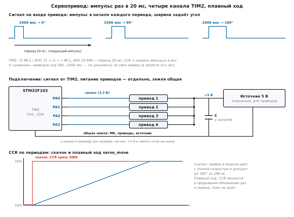
Inside an ordinary servo there is a motor, a gearbox, a potentiometer on the output shaft and a control circuit. The circuit compares the width of the incoming pulse with the potentiometer position and turns the motor until they match. The servo expects a pulse roughly every 20 ms — that is 50 Hz — and the pulse width sets the angle: 1000 µs is 0°, 1500 µs is the middle, 90°, 2000 µs is 180°. The frequency itself carries no angle: only the width matters, the period just has to be "about 20 ms".
Many servos have a wider travel — 500…2500 µs for the same 180°, and there are servos for 270° or for continuous rotation. The travel of your servo is given in its document; the project has no documents on servos, so below there are always two variants: the standard 1000…2000 µs and the "wide" 500…2500 µs, as in the lab bench. The limits themselves were not checked for any particular servo.
The servo model in the check is the same as in the bench: the angle is (pulse − 1000) / 1000 × 180, the speed is 600° per second (0.1 s per 60°), the dead band is 1°. The model stops within the dead band: 1250 µs gives 45.6°, 1750 µs gives 134.4°. If the pulse takes the angle beyond the end of travel by more than 3°, the shaft hits the stop, and the model takes the stall current of the motor — 0.65 A versus 0.01 A at rest. These are assumptions of the bench model, not servo data.
13а.2 TIM2 at 50 Hz: CCR in microseconds
It is most convenient when one timer count is one microsecond: then CCR
is the pulse width itself. TIM2 sits on APB1 (36 MHz), and since the APB1
divider is not 1, the timer frequency is doubled — 72 MHz (p. 93). PSC
= 71 gives 72 MHz / (71 + 1) = 1 MHz, ARR = 19 999 gives 20 000 counts,
a 20 ms period, 50 Hz. In PWM mode 1 the output is active while CNT <
CCR (p. 387): CCR = 1500 gives a 1500 µs pulse.
static void servo_tim2_init(void)
{
    RCC->APB1ENR |= RCC_APB1ENR_TIM2EN;
    GPIOA->CRL = (GPIOA->CRL & ~0xFFFFu) | 0xBBBBu;             /* PA0…PA3 — альтернативная функция, push-pull */
    TIM2->PSC = PSC_VAL;
    TIM2->ARR = ARR_VAL;
    TIM2->CCR1 = servo_tick(&sv[0]);
    TIM2->CCR2 = servo_tick(&sv[1]);
    TIM2->CCR3 = servo_tick(&sv[2]);
    TIM2->CCR4 = servo_tick(&sv[3]);
    TIM2->CCMR1 = TIM_CCMR1_OC1M_2 | TIM_CCMR1_OC1M_1 | TIM_CCMR1_OC1PE     /* ШИМ 1 с предзагрузкой */
                | TIM_CCMR1_OC2M_2 | TIM_CCMR1_OC2M_1 | TIM_CCMR1_OC2PE;
    TIM2->CCMR2 = TIM_CCMR2_OC3M_2 | TIM_CCMR2_OC3M_1 | TIM_CCMR2_OC3PE
                | TIM_CCMR2_OC4M_2 | TIM_CCMR2_OC4M_1 | TIM_CCMR2_OC4PE;
    TIM2->CCER = TIM_CCER_CC1E | TIM_CCER_CC2E | TIM_CCER_CC3E | TIM_CCER_CC4E;
    TIM2->CR1 = TIM_CR1_ARPE | TIM_CR1_URS;
    TIM2->EGR = TIM_EGR_UG;                                     /* загрузить PSC, ARR и CCR до старта */
    TIM2->SR = 0;
    TIM2->DIER = TIM_DIER_UIE;
    NVIC_EnableIRQ(TIM2_IRQn);
    TIM2->CR1 |= TIM_CR1_CEN;
}
The OCxPE and ARPE preload (p. 386) is not here for show: a new CCR
waits in the shadow register until the end of the period, and a pulse is
never cut in half (section 13.4). For the same reason there is UG
before the start — it moves PSC, ARR and CCR into the working
registers. URS = 1 (p. 404) keeps this UG from raising the update
flag and causing an extra interrupt. Nibble 0xB in CRL is the
alternate function push-pull at 50 MHz (p. 170). The numbers in the
firmware are checked by the compiler itself: _Static_assert on PSC =
71, ARR = 19 999 and on ARR fitting into 16 bits. With a 1 µs count
the longest period is 65.536 ms, so 20 ms fits with room to spare.
Angle to CCR. The formula is linear: pulse = min + (max − min) × angle / 180°. The angle in the code is in tenths of a degree, with rounding and with a 0…180° limit:
uint16_t servo_us(const servo_t *s, int32_t deg10)
{
    uint32_t span = (uint32_t)(s->max_us - s->min_us);
    return (uint16_t)(s->min_us + (span * (uint32_t)clamp_deg(deg10) + 900u) / 1800u);  /* с округлением */
}
| Angle | 0° | 45° | 90° | 135° | 180° |
|---|---|---|---|---|---|
CCR, travel 1000…2000 µs |
1000 | 1250 | 1500 | 1750 | 2000 |
CCR, travel 500…2500 µs |
500 | 1000 | 1500 | 2000 | 2500 |
An angle of 33.3° gives 1185 and 870; −10° and 190° are cut to 1000 and
2000 (500 and 2500 for the wide one) — the code does not go beyond the
end of travel. A CCR step of 1 µs is 0.18° for a standard servo and
0.09° for a wide one; the model dead band of 1° is more than five such
steps, so a 1 µs resolution is more than enough.
Try it in the app: Lab → bench "Servo".
The bench has one servo — on TIM1_CH1 (PA8), with the same PSC = 71
and ARR = 19 999; TIM1 additionally needs the MOE bit (13а.7). There
are also a smooth sweep with the same 10 µs step per period,
bit-banging and two mistakes from 13а.7: 1 kHz PWM and a 0.5…2.5 ms
travel on a standard servo.
13а.3 Four servos on one timer
TIM2 has four compare channels, and they share the period — the very
20 ms that all servos need. So one timer drives four servos: PA0…PA3 are
TIM2_CH1…TIM2_CH4 (p. 29), each with its own CCR. All pulses start
at the same moment, at the start of the period, and each ends at its own
time.
The update interrupt comes once per period and updates all four CCR
at once. Because of OCxPE the written value takes effect from the next
period:
void TIM2_IRQHandler(void)
{
    TIM2->SR = ~TIM_SR_UIF;
    TIM2->CCR1 = servo_tick(&sv[0]);                            /* OC1PE: новое значение — со следующего периода */
    TIM2->CCR2 = servo_tick(&sv[1]);
    TIM2->CCR3 = servo_tick(&sv[2]);
    TIM2->CCR4 = servo_tick(&sv[3]);
    periods++;
}
In the firmware four servos move between two poses: from (0°, 90°, 180°,
30°) to (180°, 45°, 0°, 120°) and back,
each move is servo_move(…, 2000). The run: CCR at the start is 1000, 1500, 2000 and 1167, the
step per period is 10; 2.5; 10 and 5 µs, and all four make their last
step in the same, 100th period — after 2 s — and settle at 2000, 1250,
1000 and 1667. The servo with a 45° move goes four times slower than the
servo with a 180° move, but they arrive together.
More than four servos means a second timer: the F103C8 and F103CB also have TIM3 and TIM4 with four channels each (section 13.1), and TIM1 is on APB2, also at 72 MHz.
13а.4 Smooth motion without delays
If you write the new angle into CCR at once, the servo jumps to it at
full speed. In the model a jump from 0° to 180° took 298 ms. For a robot
arm or a damper this is a jerk, and the motor draws the turning current
all that time. Smooth motion is a CCR that changes in small steps once
per period.
The steps are made by the update interrupt: it already comes every 20 ms,
and main does not have to wait in a single delay. The code keeps the
position in 1/16 µs so that a fractional step is not lost, and
servo_move computes the step so as to arrive in the given time, but no
faster than the speed limit:
void servo_move(servo_t *s, int32_t deg10, uint32_t time_ms)
{
    int32_t d;
    uint32_t n = time_ms / SERVO_PERIOD_MS;                     /* сколько периодов на ход */
    s->target = (int32_t)servo_us(s, deg10) * SERVO_Q;
    d = s->target - s->pos;
    if (d < 0)
        d = -d;
    if (n == 0u)
        n = 1u;
    s->step = (int32_t)(((uint32_t)d + n - 1u) / n);            /* с округлением вверх: успеть за n периодов */
    if (s->step > s->vmax)
        s->step = s->vmax;                                      /* быстрее предела — нельзя */
    if (s->step < 1)
        s->step = 1;
}

uint16_t servo_tick(servo_t *s)
{
    int32_t d = s->target - s->pos;
    if (d > s->step)
        d = s->step;
    else if (d < -s->step)
        d = -s->step;
    s->pos += d;
    return (uint16_t)((s->pos + SERVO_Q / 2) / SERVO_Q);       /* 1/16 мкс → мкс с округлением */
}
The run of servo_move(&sv, 1800, 2000) from 0°: CCR goes 1010, 1020,
1030, 1040… — 10 µs per period, that is 1.8° per 20 ms, 90° per second.
The last step is in the 100th period, after 2000 ms. The servo model
follows: 42.6° after 0.5 s, 87.6° after 1 s, 132.6° after 1.5 s, 177.6°
after 2 s, and it is within 1° of the target after 2003 ms. It lags by no
more than 1.8° — one step: its speed, 600° per second, is 6.7 times the
set one.
Speed limit. In the firmware it is 90° per second, that is 10 µs per
period. The same move in 200 ms (servo_move(&sv, 1800, 200)) or just
servo_set still takes 100 periods, 2000 ms: the step hits the limit.
So one line protects the mechanics from an "instantly" command.
The target and the step are changed in main and read by the interrupt,
so in the firmware servo_move for the four servos is called with
interrupts disabled — otherwise the interrupt could take the new target
with the old step. The same approach works for SysTick: the step can be
made in its interrupt if the servo timer is busy with something else —
what matters is that the step comes once per PWM period, not more often.
13а.5 Bit-banging — and why it is worse
The same signal can be made without a timer: pin high, a delay for the pulse width, pin low, a delay until the end of the period. The example "A servo by bit-banging" in the lab bench is made this way. It works — but:
- the core is busy with delays all the time: 20 ms out of 20 ms for one servo, and four servos with different pulses already need sorting of edges;
- a delay counted in cycles knows nothing about interrupts. An interrupt that comes during the pulse stretches it by its own length.
The model: an interrupt every 1 ms lasting 10 µs (the length is an
assumption of the model, not a measurement), the bit-banging holds
1500 µs, a 5 s run. Without interrupts there are 250 pulses, all of
1500 µs, and the servo did not move. With interrupts there are 248
pulses: 118 of 1510 µs and 130 of 1520 µs, depending on how many
interrupts fell into the pulse, and the period grew to 20.2…20.21 ms.
10 µs is 1.8°, more than the dead band: the servo model moved 101 times
in 5 s. This is the "jitter". With a timer the pulse width does not
depend on the program at all: the update interrupt may be late, but
CCR already sits in the shadow register.
13а.6 Power: a separate 5 V and a common ground
A servo motor draws current in bursts: when a turn starts, under load and especially at the stop. How much exactly is given in the servo document — the project does not have it, so the currents below come only from the bench model (0.25 A for a turn, 0.65 A at the stop — assumptions). Even the model shows how four servos add up: a jump of all four at once is 1 A, the same jumps one after another, 300 ms apart, are 0.28 A at the peak.
Hence the rules, without numbers — the numbers come from the servo and supply documents:
- A separate 5 V supply for the servos, not the 3.3 V pin and not the regulator of the board with the controller. A current burst makes the supply sag, and if the controller sits on the same line, the sag can reset it — the servo twitched, the controller restarted, the servo twitched again.
- A common ground. The pulse is the signal voltage relative to the servo ground; without a common wire the servo has no reference, and the signal is undefined for it. The servo ground is run to the supply with a thick wire, and to the controller with a separate one, so that the motor current does not flow through the board ground.
- A capacitor at the servo connector smooths short current bursts; its capacitance is taken from the servo and supply documents.
- Do not start all at once. Smooth motion from 13а.4 and starting one after another spread the load on the supply; in the bench model the peak current went down with starting one after another, but there is no acceleration in the model, and the starting current of a real motor depends on it.
3.3 V at the signal input. The controller gives a 3.3 V pulse, while
the servo is powered from 5 V. Whether its input accepts 3.3 V as a one
is given in the servo document; the project does not have it, and this
was not checked. If it does not — a level shifter or an open drain with a
pull-up to 5 V. The latter is possible only on a pin with 5 V tolerance:
PA0…PA3 do not have it (p. 29), PA8 does (p. 31). For PA8 the firmware
has an open-drain variant — nibble 0xF in CRH (p. 171):
void servo_tim1_init(uint16_t pulse_us, int open_drain)
{
    RCC->APB2ENR |= RCC_APB2ENR_TIM1EN;
    GPIOA->CRH = (GPIOA->CRH & ~0xFu) | (open_drain ? 0xFu : 0xBu);   /* PA8: AF открытый сток или push-pull */
    TIM1->PSC = PSC_VAL;                                        /* TIM1 на APB2 = 72 МГц */
    TIM1->ARR = ARR_VAL;
    TIM1->CCR1 = pulse_us;
    TIM1->CCMR1 = TIM_CCMR1_OC1M_2 | TIM_CCMR1_OC1M_1 | TIM_CCMR1_OC1PE;
    TIM1->CCER = TIM_CCER_CC1E;
    TIM1->BDTR = TIM_BDTR_MOE;                                  /* без MOE выход TIM1 молчит */
    TIM1->CR1 = TIM_CR1_ARPE;
    TIM1->EGR = TIM_EGR_UG;
    TIM1->CR1 |= TIM_CR1_CEN;
}
The pull-up value and the pulse edge with it were not calculated here.
13а.7 Pitfalls
The servo jitters and hums, 1 kHz PWM. The timer was set up as for an
LED: ARR = 999, a 1 ms period. The bench model holds the angle with a
period from 5 to 40 ms, and at 1 ms and 41 ms it jitters. You need ARR
= 19 999 with a 1 MHz count.
A forgotten divider. PSC = 0: a 72 MHz count, CCR = 1500 is a
20.8 µs pulse, a 0.2778 ms period. The model jitters, the angle does not
hold.
The shaft is at the stop, the servo heats up. The 500…2500 µs travel
of a "wide" servo on a standard one: 500 and 2500 µs take the shaft beyond
the end, and the model draws the 0.65 A of a stalled motor. Take the
travel from the document of your servo and limit the angle in the code,
as servo_us does.
The pulse twitches although the code is "right". Bit-banging: an interrupt of 10 µs stretches the pulse by 1.8° — 101 moves in 5 s in the model. Only a timer.
The timer counts, but the pin is silent. TIM1: no MOE in BDTR
(p. 358) — TIM2 has no such bit, and code moved from TIM2 to TIM1 stays
silent (section 13.5). Or the pin is not switched to the alternate
function: nibble 0xB, not 0x2.
The pulse is cut when the angle changes. No OCxPE: a new CCR
written in the middle of a pulse takes effect at once, and one pulse
comes out with the wrong width.
The controller reboots when the servos move. The servos share the supply with the controller. A separate supply, a common ground, a capacitor at the connector.
The servo does not respond to 3.3 V. The servo input expects a level from 5 V. A level shifter or an open drain with a pull-up to 5 V — only on an FT pin, like PA8.
13а.8 Summary
- A servo expects a pulse every 20 ms (50 Hz); the angle is set by the width: 1000 µs is 0°, 1500 µs is 90°, 2000 µs is 180°; "wide" ones have 500…2500 µs, per the servo document.
- TIM2 on the F103: 72 MHz,
PSC= 71 — a 1 µs count,ARR= 19 999 — 20 ms;CCR= the pulse width in µs; a 1 µs step is 0.18°. - Four servos are four channels of one timer; the update interrupt every
20 ms writes all four
CCR, andOCxPEkeeps a pulse from being cut. - Smooth motion is a
CCRstep once per period: 10 µs per period is 90° per second, 180° in 2 s, 100 periods; a jump in the model takes 298 ms. - Bit-banging takes the whole core, and a 10 µs interrupt stretches the pulse to 1510–1520 µs — the servo jitters.
- The servo supply is a separate 5 V source, a common ground, a capacitor at the connector; 3.3 V at the input — per the servo document.
Full sources
servo13b.h — period constants, servo state, functions.
/* servo13b.h — раздел 13а: сервопривод без регистров — угол в импульс и плавное движение.
 * Счёт таймера — 1 МГц, поэтому CCR равен ширине импульса в микросекундах.
 * В прошивке fw13b.c servo_tick() зовёт прерывание обновления TIM2 раз в период ШИМ (20 мс),
 * в стенде host13b.c — модель model13b.py; код один и тот же. */
#ifndef SERVO13B_H
#define SERVO13B_H
#include <stdint.h>

#define SERVO_PERIOD_US 20000u          /* 50 Гц: период ШИМ 20 мс */
#define SERVO_PERIOD_MS 20u
#define SERVO_Q         16              /* положение хранится в 1/16 мкс: дробный шаг не теряется */

typedef struct {
    uint16_t min_us, max_us;            /* импульс для 0° и для 180° */
    int32_t pos;                        /* текущий импульс, 1/16 мкс */
    int32_t target;                     /* куда идём, 1/16 мкс */
    int32_t step;                       /* шаг за период, 1/16 мкс */
    int32_t vmax;                       /* предел скорости: шаг за период, 1/16 мкс */
} servo_t;

/* min_us/max_us — ход привода по его документу; vmax — предел, градусов в секунду; deg10 — угол в 0,1°. */
void servo_init(servo_t *s, uint16_t min_us, uint16_t max_us, uint16_t vmax_dps, int32_t deg10);
uint16_t servo_us(const servo_t *s, int32_t deg10);              /* угол → импульс, мкс (0…180°, с ограничением) */
void servo_set(servo_t *s, int32_t deg10);                       /* идти к углу с предельной скоростью */
void servo_move(servo_t *s, int32_t deg10, uint32_t time_ms);    /* дойти за time_ms, но не быстрее vmax */
uint16_t servo_tick(servo_t *s);                                 /* раз в период: следующий CCR, мкс */
int servo_busy(const servo_t *s);

#endif
servo13b.c — angle to pulse and smooth motion without registers: the part shared by the firmware and the bench.
/* servo13b.c — раздел 13а: угол в импульс и плавное движение сервопривода (без регистров). */
#include "servo13b.h"

static int32_t clamp_deg(int32_t deg10)
{
    return deg10 < 0 ? 0 : (deg10 > 1800 ? 1800 : deg10);    /* за край хода не выходим: там упор */
}

uint16_t servo_us(const servo_t *s, int32_t deg10)
{
    uint32_t span = (uint32_t)(s->max_us - s->min_us);
    return (uint16_t)(s->min_us + (span * (uint32_t)clamp_deg(deg10) + 900u) / 1800u);  /* с округлением */
}

void servo_init(servo_t *s, uint16_t min_us, uint16_t max_us, uint16_t vmax_dps, int32_t deg10)
{
    s->min_us = min_us;
    s->max_us = max_us;
    /* градусы в секунду → 1/16 мкс за период: span × 16 × v × 20 мс / (180° × 1000 мс) */
    s->vmax = (int32_t)(((uint32_t)(max_us - min_us) * SERVO_Q * vmax_dps * SERVO_PERIOD_MS + 90000u) / 180000u);
    if (s->vmax < 1)
        s->vmax = 1;
    s->pos = s->target = (int32_t)servo_us(s, deg10) * SERVO_Q;
    s->step = s->vmax;
}

void servo_set(servo_t *s, int32_t deg10)
{
    s->target = (int32_t)servo_us(s, deg10) * SERVO_Q;
    s->step = s->vmax;
}

void servo_move(servo_t *s, int32_t deg10, uint32_t time_ms)
{
    int32_t d;
    uint32_t n = time_ms / SERVO_PERIOD_MS;                     /* сколько периодов на ход */
    s->target = (int32_t)servo_us(s, deg10) * SERVO_Q;
    d = s->target - s->pos;
    if (d < 0)
        d = -d;
    if (n == 0u)
        n = 1u;
    s->step = (int32_t)(((uint32_t)d + n - 1u) / n);            /* с округлением вверх: успеть за n периодов */
    if (s->step > s->vmax)
        s->step = s->vmax;                                      /* быстрее предела — нельзя */
    if (s->step < 1)
        s->step = 1;
}

uint16_t servo_tick(servo_t *s)
{
    int32_t d = s->target - s->pos;
    if (d > s->step)
        d = s->step;
    else if (d < -s->step)
        d = -s->step;
    s->pos += d;
    return (uint16_t)((s->pos + SERVO_Q / 2) / SERVO_Q);       /* 1/16 мкс → мкс с округлением */
}

int servo_busy(const servo_t *s)
{
    return s->pos != s->target;
}
fw13b.c — STM32F103 firmware: four servos on TIM2 (PA0…PA3), one on TIM1 (PA8).
/* fw13b.c — раздел 13а: четыре сервопривода на TIM2 STM32F103 (BluePill), 72 МГц.
 * TIM2_CH1…CH4 на PA0…PA3, счёт 1 МГц, период 20 мс (50 Гц), CCR — ширина импульса в мкс.
 * Прерывание обновления раз в 20 мс двигает все четыре привода на шаг (servo_tick) — без задержек в main.
 * Один привод на TIM1_CH1 (PA8, вывод с допуском 5 В) — servo_tim1_init: у TIM1 нужен бит MOE.
 * Тактирование до 72 МГц — как в разделе 6 (здесь не повторяется); APB1 = 36 МГц, таймеры на нём — 72 МГц. */
#include "stm32f10x.h"
#include "servo13b.h"

#define TIM_HZ   72000000u
#define TICK_HZ  1000000u                                       /* счёт 1 МГц: 1 мкс на отсчёт */
#define PSC_VAL  (TIM_HZ / TICK_HZ - 1u)
#define ARR_VAL  (SERVO_PERIOD_US - 1u)

_Static_assert(PSC_VAL == 71u, "72 МГц / (71 + 1) = 1 МГц");
_Static_assert(ARR_VAL == 19999u, "20 000 отсчётов по 1 мкс = 20 мс");
_Static_assert(ARR_VAL <= 0xFFFFu, "ARR у TIM2 на F103 — 16 бит");

static servo_t sv[4];
static volatile uint32_t periods;                               /* счётчик периодов: часы программы */

void TIM2_IRQHandler(void)
{
    TIM2->SR = ~TIM_SR_UIF;
    TIM2->CCR1 = servo_tick(&sv[0]);                            /* OC1PE: новое значение — со следующего периода */
    TIM2->CCR2 = servo_tick(&sv[1]);
    TIM2->CCR3 = servo_tick(&sv[2]);
    TIM2->CCR4 = servo_tick(&sv[3]);
    periods++;
}

static void servo_tim2_init(void)
{
    RCC->APB1ENR |= RCC_APB1ENR_TIM2EN;
    GPIOA->CRL = (GPIOA->CRL & ~0xFFFFu) | 0xBBBBu;             /* PA0…PA3 — альтернативная функция, push-pull */
    TIM2->PSC = PSC_VAL;
    TIM2->ARR = ARR_VAL;
    TIM2->CCR1 = servo_tick(&sv[0]);
    TIM2->CCR2 = servo_tick(&sv[1]);
    TIM2->CCR3 = servo_tick(&sv[2]);
    TIM2->CCR4 = servo_tick(&sv[3]);
    TIM2->CCMR1 = TIM_CCMR1_OC1M_2 | TIM_CCMR1_OC1M_1 | TIM_CCMR1_OC1PE     /* ШИМ 1 с предзагрузкой */
                | TIM_CCMR1_OC2M_2 | TIM_CCMR1_OC2M_1 | TIM_CCMR1_OC2PE;
    TIM2->CCMR2 = TIM_CCMR2_OC3M_2 | TIM_CCMR2_OC3M_1 | TIM_CCMR2_OC3PE
                | TIM_CCMR2_OC4M_2 | TIM_CCMR2_OC4M_1 | TIM_CCMR2_OC4PE;
    TIM2->CCER = TIM_CCER_CC1E | TIM_CCER_CC2E | TIM_CCER_CC3E | TIM_CCER_CC4E;
    TIM2->CR1 = TIM_CR1_ARPE | TIM_CR1_URS;
    TIM2->EGR = TIM_EGR_UG;                                     /* загрузить PSC, ARR и CCR до старта */
    TIM2->SR = 0;
    TIM2->DIER = TIM_DIER_UIE;
    NVIC_EnableIRQ(TIM2_IRQn);
    TIM2->CR1 |= TIM_CR1_CEN;
}

/* Один привод на PA8: вывод допускает 5 В, поэтому можно открытый сток с подтяжкой к питанию привода. */
void servo_tim1_init(uint16_t pulse_us, int open_drain)
{
    RCC->APB2ENR |= RCC_APB2ENR_TIM1EN;
    GPIOA->CRH = (GPIOA->CRH & ~0xFu) | (open_drain ? 0xFu : 0xBu);   /* PA8: AF открытый сток или push-pull */
    TIM1->PSC = PSC_VAL;                                        /* TIM1 на APB2 = 72 МГц */
    TIM1->ARR = ARR_VAL;
    TIM1->CCR1 = pulse_us;
    TIM1->CCMR1 = TIM_CCMR1_OC1M_2 | TIM_CCMR1_OC1M_1 | TIM_CCMR1_OC1PE;
    TIM1->CCER = TIM_CCER_CC1E;
    TIM1->BDTR = TIM_BDTR_MOE;                                  /* без MOE выход TIM1 молчит */
    TIM1->CR1 = TIM_CR1_ARPE;
    TIM1->EGR = TIM_EGR_UG;
    TIM1->CR1 |= TIM_CR1_CEN;
}

static uint32_t now_periods(void)
{
    return periods;
}

int main(void)
{
    static const int16_t pose[2][4] = {{0, 900, 1800, 300}, {1800, 450, 0, 1200}};   /* углы в 0,1° */
    uint32_t t0;
    int k = 0;
    RCC->APB2ENR |= RCC_APB2ENR_IOPAEN;
    for (int i = 0; i < 4; i++)
        servo_init(&sv[i], 1000u, 2000u, 90u, pose[0][i]);     /* ход 1…2 мс, не быстрее 90°/с */
    servo_tim2_init();
    t0 = now_periods();
    for (;;) {
        __WFI();                                                /* спим до прерывания: ядро свободно */
        if (now_periods() - t0 >= 150u) {                       /* каждые 3 с — новая поза */
            t0 = now_periods();
            k ^= 1;
            __disable_irq();                                    /* цель и шаг меняются вместе */
            for (int i = 0; i < 4; i++)
                servo_move(&sv[i], pose[k][i], 2000u);          /* все четыре приходят разом, за 2 с */
            __enable_irq();
        }
    }
}
Next: section 13б "Buzzer: active and passive, notes on a timer, a non-blocking melody".