 Embedded HandbookApps
81. Sensors on a prototype and fighting noise
A sensor turns a physical quantity into an electrical signal, and a microcontroller turns the signal into a number. Between them there is always noise: the readings "jitter" even when the potentiometer knob is not moving. This section covers the kinds of sensors, how to convert an ADC code into the units you need correctly, and which filter to choose to remove the noise without losing speed.
All filters in this section were built with armclang for Cortex-M3 and M0 and checked
by a test on a computer: with a step, with noise and with a single outlier. Every
number in the test was recalculated in Python with filters written anew.
Terms used in the documentation
Term Meaning sensor, transducer a device that converts a physical quantity into a signal analog / digital output a voltage output / a number sent over an interface resolution, LSB the number of bits, the size of one quantisation step full scale the whole input range of the converter ratiometric measurement a measurement relative to the same reference that powers the sensor noise, outlier (spike) random jitter, a single wild sample moving average the mean of the last N samples exponential moving average (EMA) smoothing where old samples fade out gradually median filter a filter that takes the middle value of several samples step response how the output follows a sudden step at the input fixed-point an integer that stores a fraction with an implied scale
81.1 Kinds of sensors
By output — two large classes:
- analog sensors output a voltage: a potentiometer, a thermistor, a photoresistor, a current sensor. They are read by the ADC (section 14), and all the noise on the line ends up in the reading;
- digital sensors digitise the quantity themselves and return a number over I²C, SPI or their own one-wire protocol (sections 17 and 18). Line noise hardly bothers them, but a protocol appears, and it can fail.
By operating principle — resistive (the resistance depends on the quantity), capacitive (touch buttons, humidity — section 45), inductive (proximity of metal), piezoelectric (impact, vibration), photoelectric (light).
For a prototype the easiest place to start is a potentiometer: it is a voltage divider (section 50.2), and its reading is easy to check by eye.
81.2 From ADC code to the units you need
The Uno has a 10-bit ADC — codes 0…1023. The F103 and F407 have a 12-bit one, 0…4095, and the voltage is calculated as code × Vref / 4095 (section 14). In integer arithmetic, with rounding and without losing range:
#define VREF_MV 3300
#define ADC_MAX 4095

uint16_t adc_to_mv(uint16_t code)
{
    return (uint16_t)(((uint32_t)code * VREF_MV + ADC_MAX / 2) / ADC_MAX);
}
Code 2048 gives 1650 mV, 4095 gives exactly 3300. The quantisation step is 0.806 mV.
The cast to uint32_t is mandatory: 4095 * 3300 does not fit into
16 bits, and on AVR int is exactly that wide (section 80.1).
⚠️
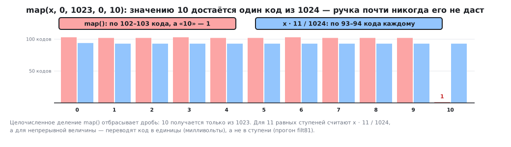
map()divides the scale unevenly. In Arduino you scale with the functionmap(x, 0, 1023, 0, 10). It computes in integers with truncation, and the value 10 comes from exactly one code out of 1024 — from 1023. The other ten values get 102–103 codes each. The potentiometer knob will almost never give "10". To split the scale into 11 equal steps, computex * 11 / 1024— 93–94 codes per step. A continuous quantity needs conversion into units, likeadc_to_mvabove, not steps.
Ratiometric measurement. A potentiometer powered from the same
reference as the ADC gives a code that does not depend on the supply voltage: at
a quarter of its travel it is 1024 at 3.0 V, at 3.3 and at 3.6 V alike. The supply
cancels out. On the F103 in LQFP packages with up to 64 pins the ADC reference is
the analog supply VDDA, so it is enough to power the potentiometer from
it. In packages with 100 pins or more the reference is applied to a separate VREF+ pin. But if the sensor is powered
from a separate 3.3 V source while the reference has sagged to 3.0 V, the code becomes
1126 — the change in supply goes straight into the reading.
81.3 Where noise comes from
- The supply. A switching converter, LEDs, a radio module — anything that draws current in bursts makes the ADC reference swing.
- Wires. A long wire to the sensor is an antenna; plus the voltage drop across it (section 49.8).
- Ground. A common wire carrying motor current shifts the "zero" of the measurement.
- Source resistance. The ADC sampling capacitor charges through the sensor, and with a high resistance and a short sampling time it does not have time to charge: the code starts to depend on the previous channel. What helps is a longer sampling time, a lower-resistance potentiometer or a capacitor at the input (section 14).
- The sensor and the ADC themselves — their own noise, which nothing removes except averaging.
Noise is reduced in hardware first: a capacitor at the ADC input (section 50.6), an RC filter (section 62.7), a separate ground, powering the sensor from the reference. A software filter is the last stage, not a replacement for the first ones.
81.4 Three filters and one wrong one
Moving average — the mean of the last N samples. The sum is not recalculated from scratch: the new sample is added to it and the one leaving the window is subtracted.
#define MA_N 16

typedef struct {
    uint16_t buf[MA_N];
    uint32_t sum;
    uint8_t pos;
    uint8_t filled;
} ma_t;

uint16_t ma_update(ma_t *f, uint16_t x)
{
    f->sum += x;
    f->sum -= f->buf[f->pos];   /* уходит самый старый — сумма не пересчитывается */
    f->buf[f->pos] = x;
    f->pos = (uint8_t)((f->pos + 1) % MA_N);
    if (f->filled < MA_N)
        f->filled++;
    return (uint16_t)(f->sum / f->filled);
}
Exponential smoothing — each new sample moves the result a fraction of the way towards itself: y ← y + (x − y) / 8. Memory — a single number.
#define EMA_K 3                 /* коэффициент 1/8 */

/* Неверно: результат хранится без дробной части, деление отбрасывает
 * остаток — показание застревает, не дойдя до входа. */
uint16_t ema_naive(uint16_t *y, uint16_t x)
{
    *y = (uint16_t)(*y + ((int32_t)x - *y) / (1 << EMA_K));
    return *y;
}

/* Верно: состояние хранится умноженным на 2^K — дробная часть не теряется. */
uint16_t ema_update(uint32_t *acc, uint16_t x)
{
    *acc += x - (*acc >> EMA_K);
    return (uint16_t)(*acc >> EMA_K);
}
It is this filter that examples often call a "running average" — but it is not a window average, it is smoothing: it has no buffer and no window, and the contribution of old samples fades out gradually.
Median of three — the middle value of the last three samples.
uint16_t med3(uint16_t a, uint16_t b, uint16_t c)
{
    uint16_t t;
    if (a > b) { t = a; a = b; b = t; }
    if (b > c) { t = b; b = c; c = t; }
    return a > b ? a : b;
}
What the test showed
Step — the input jumps from 0 to 1000:
| Filter | To 95 % | Final value |
|---|---|---|
| average of 16 | 16 samples (and straight to 100 %) | 1000 |
| smoothing 1/8 | 23 samples | 1000 |
| smoothing 1/8, naive | 23 samples | 993 — and not a step further |
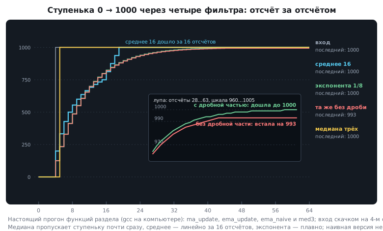
The naive variant looks the same until you look at the last digits:
as soon as less than eight codes remain to the target, (x − y) / 8 is
zero, and the reading gets stuck. A shortfall of 7 codes is 5.6 mV, an error
that never goes away. The figure 23 agrees with the formula: (7/8)^k ≤ 0.05
at k = 23.
Noise — uniform ±50 codes around 2000, five thousand samples:
| Standard deviation | Improvement | |
|---|---|---|
| no filter | 29.18 | — |
| average of 16 | 7.50 | 3.9 times (theory √16 = 4) |
| smoothing 1/8 | 7.65 | 3.8 times (theory √15 ≈ 3.87) |
Single outlier — one sample of 4095 among values of 2000:
| Filter | Largest deviation |
|---|---|
| average of 16 | 130 — and it stays for 16 samples |
| smoothing 1/8 | 261 — and it decays |
| median of three | 0 |
How to choose
| Average of 16 | Smoothing 1/8 | Median of three | |
|---|---|---|---|
| memory | 40 bytes | 4 bytes | two previous samples |
| against noise | good | good | weak |
| against outliers | smears them | smears them | removes them |
| delay | exactly N samples | smooth, 95 % in 23 | one sample |
| division | yes: on M3 — udiv, on M0 — a function call |
no, only shifts | no |
A common combination is a median of three followed by smoothing: the median removes single outliers, the smoothing removes noise. The smoothing coefficient is taken as a power of two: then division turns into a shift, and on Cortex-M0, which has no divide instruction (section 75.4), the filter stays cheap.
A filter always means delay. Smoothing 1/8 with sampling every 10 ms reaches 95 % in 230 ms — unnoticeable for a thermometer, but for a controller it may turn out to be too slow (section 47).
81.5 Reading a sensor without stopping the program
The example "add up 30 samples in a loop and divide" works, but stops the program for the whole duration of the measurement. The filters above are built differently: each call is one sample, and the result is always ready. The samples come from the ADC interrupt or via DMA (sections 9 and 14), and the program takes the current filtered value when it needs it.
One more consequence of the filter receiving a sample rather than reading the ADC itself: it can be checked on a computer, just as the functions of this section were checked (section 79.5).
81.6 Pitfalls
The readings jitter in the last digit. That is normal: the step of a 12-bit ADC is 0.8 mV. Hardware first — capacitor, ground, reference — then the filter.
The potentiometer knob does not reach the maximum. map() gives the extreme
value one code out of 1024.
The smoothed value falls short of the input by a few units. The exponential smoothing stores the result without a fractional part.
After the filter the spikes are still there, only wider. The average and the smoothing smear an outlier; you need a median.
The controller started oscillating after a filter was added. The filter added delay.
The sensor reading "drifts" with the supply voltage. The sensor is not powered from the ADC reference.
The program freezes for the duration of the measurement. Averaging in a loop instead of a filter that works one sample at a time.
Scaling gives garbage on AVR and is correct on STM32. The intermediate
product did not fit into a 16-bit int.
81.7 Summary
- Analog sensors are read by the ADC, and line noise ends up in the reading; digital ones return a number, but add a protocol.
- A 12-bit ADC code is converted into millivolts as code × 3300 / 4095 in
32-bit arithmetic; Arduino's
map()divides the scale unevenly. - A sensor powered from the ADC reference is insensitive to supply fluctuations.
- Noise is suppressed in hardware first, then with a filter.
- A moving average of 16 reduces noise 3.9 times and holds an outlier for 16 samples; smoothing 1/8 reduces it 3.8 times with four bytes of memory; a median of three removes single outliers completely.
- Integer exponential smoothing stores its state multiplied by 2^K — otherwise it gets stuck before reaching the input.
- A filter works one sample at a time and does not stop the program; noise suppression is paid for with delay.
Next: section 81а "Digital filters: FIR, IIR and CMSIS-DSP" — filters with a specified passband and ready-made library functions.