 Embedded HandbookApps
36н. Oscilloscope and generator at work: a practicum on the DHO900 and DG900 Pro
Sections 36г–36м took the instruments apart one at a time: the oscilloscope control by control, the generator from the inside. Here they work together, on the bench next to the board. There are twelve tasks, and each follows the same order: why, what to connect to what, what to set on the generator, what to set on the oscilloscope, what you should get in numbers, and where people usually go wrong. The "what you should get" numbers were computed in advance by a model, so a mismatch on the bench is a reason to look for a mistake in the circuit or in the firmware, not in the instrument.
The instruments are the author's: a RIGOL DHO900 oscilloscope and a two-channel RIGOL DG902 Pro generator from the DG900 Pro series. Menu item names are given in English, as on the screens. A DG900 Pro series generator is a DDS generator with point memory (how it works is in 36к): CH1 and CH2 outputs on the front panel; on the rear, one [AUX IN/OUT] connector per channel (the Sync output, an external trigger or modulation input), a 10 MHz reference input and output, USB and LAN. It also has its own frequency counter with a separate Counter input on the front panel.
Sources. Generator: DG900 Pro User Guide (Books/Manual_RIGOL_DG900_Pro.pdf,
below "DG guide"), DG900 Pro Quick Guide
(Books/DG900 Pro Series Quick Guide.pdf, "DG quick guide") and the short
Russian guide (Books/rigol_dg900_pro_manual1.pdf, "Russian DG guide");
we have neither a datasheet nor a programming guide for the DG900 Pro.
Oscilloscope: DHO900 Datasheet (Books/dho900-datasheet.pdf, "datasheet"),
DHO900 User Guide (Books/DHO900_UserGuide_EN.pdf, "DHO guide"),
DHO800/DHO900 Programming Guide (Books/DHO800900_ProgrammingGuide_EN.pdf,
"programming guide"). All pages are PDF-file pages. The task numbers come
from the run of _verify/prac36n/ in the stm-lab:1 container:
model36n.py (Python 3.11, numpy 1.24), the edge through the cable —
ngspice-39 (ring36n.cir), the listing in 36н.13 — against stub
instruments (stub36n.py).
What it is called in the documentation
Original Meaning Imped: HighZ, Load which load the generator recalculates the on-screen number for Ampl/HighL, Offset/LowL amplitude and offset, or high and low levels Sweep: Linear, Log, Step; Mark frequency sweep; the mark is the frequency where Sync falls Burst: NCycle, Gated; Cycles, Idle Level a burst of N periods or gated; number of periods, level between bursts Sync, Trig Out, [AUX IN/OUT] sync output, trigger output, rear-panel connector Align Phase, Coupling, Track align channel phases, link parameters, repeat a channel Mod: AM, FM, SUM; Depth, Freq Dev modulation; depth, frequency deviation; SUM adds another signal Delay(r-r), Phase(r-r) delay and phase between the edges of two channels (DHO900) feed-through termination a 50 Ω pass-through load on the oscilloscope connector
36н.1 The bench: what all tasks have in common
A generator output is not a power supply. Its 50 Ω is a resistance placed in series with the output inside (DG guide p. 23, 97), not a protection. You do not short the output, you do not apply someone else's voltage to it, and you do not power a circuit from it: that is what a bench supply is for (36а.8). Whether the output is protected against a short or against external voltage is not stated in the documents — assume it is not.
How much it can deliver. With a HighZ load, up to 20 Vpp at frequencies up to 50 MHz; DC (Arb → DC) from −10 to +10 V (DG guide p. 38, 52; Russian DG guide p. 18). That is an EMF up to ±10 V: three times the supply of an STM32 pin. So in the tasks below the board input is protected with a resistor per 62.3: at least (10 − 4.0) V / 5 mA = 1.2 kΩ; we fit 1.5 kΩ, and with the generator's 50 Ω the current through the internal diode is no more than 3.87 mA. A 5 V tolerant pin is not protected this way — see 62.3.
Switched on — check the output. The DG900 Pro defaults to Load Last = Last: on power-up it restores whatever was set at power-off (DG guide p. 108). Yesterday's 20 Vpp end up on the board today with the first press of the output key. Bench rule: first connect the generator output to the oscilloscope without the board, then to the board.
Grounds. The generator is powered from a USB PD 15 V, 3 A adapter, and its rear panel has a separate chassis ground terminal (DG guide p. 25; DG quick guide p. 12, 14). Whether the shields of the output BNCs are tied to protective earth through the adapter is not stated in the documents. On the DHO900 the probe ground is the mains outlet ground (36а.5, 36з.1). Before you start, check continuity between the generator BNC shield and the oscilloscope ground; if there is none, join them with a wire near the board, not through the board.
Cables. BNC–BNC 50 Ω from the generator; a 1:10 probe to the board pins (36а.2). The DHO900 has no 50 Ω input — only 1 MΩ ±1 % and 15 pF ±3 pF (datasheet p. 10; 36г.6), so where a matched load is needed you fit a feed-through 50 Ω termination on the input. And triggering: the DHO900 has no external trigger input, the source is CH1–CH4 or D0–D15 (datasheet p. 13; 36д.6), so the generator Sync signal takes one channel.
Task order. Goal → connection → generator → oscilloscope → what you should get → typical mistake. Generator menus: the waveform is Wave Type, the mode is Output Mode (Cont, Mod, Sweep, Burst), channel parameters (Sync, Imped, Invert) are on the Channel tab (DG guide p. 26, 93–97).
36н.2 Task 1: why the screen shows twice as much
Goal. Understand that the number on the generator screen is a recalculation, not a measurement, and set the load so that it matches what the oscilloscope sees. The physics is in 36к.3; here — the menu and high frequency.
Connection. Generator CH1 with a BNC cable straight to oscilloscope CH1; the second experiment is with a feed-through 50 Ω termination on the oscilloscope input.
Generator. Sine, Freq 1 kHz, Ampl 1 Vpp, Offset 0. Channel tab → Imped: first Load (50 Ω), then HighZ. Inside the output there is always 50 Ω in series, and the Imped setting changes only the recalculation: on switching from 50 Ω to HighZ the 5 Vpp on screen becomes 10 Vpp, while the signal at the connector stays the same (DG guide p. 97). Load can be set as a number from 1 Ω to 10 kΩ — then the screen shows the voltage on such a load: with an EMF of 1 V and Load 1 kΩ — 0.9524 V. dBm is available only with Load: with HighZ, power is not defined (DG guide p. 39–40).
Oscilloscope. CH1, DC, 200 mV/div; Measure → Vpp; Edge trigger on CH1.
What you should get (model: a 50 Ω divider and a load with 15 pF; with an output of exactly 50 Ω the cable length does not affect the amplitude):
| frequency | Load 50 Ω, "1 Vpp", 1 MΩ input | same, with a 50 Ω termination |
|---|---|---|
| 1 kHz | 1.9999 V | 1.0000 V |
| 10 MHz | 1.9977 V | 0.9997 V |
| 70 MHz | 1.8992 V | 0.9867 V |
At 70 MHz — the top sine frequency of the DG902 Pro (DG guide p. 38) — the 15 pF of the oscilloscope input is already 151.6 Ω, and the "doubling" is incomplete. On top of this comes the bandwidth roll-off of the oscilloscope itself (36а.3). With HighZ on the generator and a 1 MΩ input, the generator screen and the oscilloscope agree. The DG900 Pro factory setting is HighZ (DG guide p. 116), not 50 Ω as on many generators: from your own instrument into a board with a high-impedance input there will be no doubling.
Typical mistake. Fitting a feed-through 50 Ω termination but leaving the generator at HighZ: the oscilloscope shows half of what was set — less, not more. Rule: Imped on the generator equals what is really at the end of the cable.
36н.3 Task 2: the frequency response of an RC network by sweeping
Goal. Measure a filter's frequency response without a Bode plot: the generator sweeps the frequency, the oscilloscope draws the output envelope, the generator mark shows which frequency is where. The DHO900 Bode plot exists only on the DHO914S and DHO924S (36к.6, 36е.24); this method works on any model.
Connection. RC: 4.7 kΩ in series, 10 nF to ground — cutoff 3386.3 Hz. Generator output CH1 to the network input and to oscilloscope CH1 (BNC tee), network output with a 1:10 probe to CH2. The generator rear [CH1 AUX IN/OUT] to oscilloscope CH3: this is Sync.
Generator. Sine, Ampl 1 Vpp, Imped HighZ. Output Mode → Sweep: Sweep Type Log, Start 100 Hz, Stop 100 kHz, Sweep Time 10 s, Source Internal. Channel tab: Sync On, Mark On, Mark Freq 3386.3 Hz. During a sweep, Sync rises at the start and falls at the mark frequency (DG guide p. 74, 94–95). A logarithmic sweep gives equal shares of time to each decade; the law F = P^T is given in the DG guide (p. 70).
Oscilloscope. 1 s/div — 10 s per screen. Roll (Horizontal → Roll) — OFF: then at 200 ms/div and slower the instrument records a slow sweep with triggering (DHO guide p. 74), while in Roll there is no triggering at all. Trigger — Edge, CH3, rising, Normal. Acquisition mode — Peak: at 1 s/div a memory point is far rarer than the signal period, and without the peak detector the envelope falls apart into aliasing (36г.15, 36г.16). Manual cursors (36е.2): one on the falling edge of CH3, the second at 0.707 of the initial CH2 amplitude.
What you should get. A decade takes 3.333 s. Sync falls 5.099 s after the sweep start, and at that moment the CH2 amplitude is 0.707 of the initial one (−3.01 dB). At 100 Hz the loss is −0.004 dB, at 100 kHz — −29.41 dB, that is 3.38 % of the amplitude. The network time constant is 47 µs: with 3.3 s per decade the filter keeps up with margin (how this breaks with a fast sweep — 36к.7).
Typical mistake. Sweep Type Linear: the whole band below the cutoff, from 100 to 3386 Hz, passes in 3.29 % of the time — less than a third of a division on screen. For a frequency response — Log only. The second mistake is viewing in Normal: with a slow time base the envelope breaks up and "rings" with false beats.
36н.4 Task 3: checking the ADC with a sine
Goal. Feed a known sine to an ADC pin and verify what the firmware sees: amplitude in codes, midpoint, frequency. And see with your own eyes aliasing when the signal frequency is above half the sampling frequency.
Connection. Generator CH1 → 1.5 kΩ resistor (36н.1) → PA0 (ADC input) of an F103 board; probe CH1 of the oscilloscope on PA0. The firmware starts the ADC from a timer 10000 times per second (14.5, 14.6) and toggles a marker pin on every conversion (36а.7) — that goes to CH2.
Generator. Sine, Freq 1 kHz, Imped HighZ, Ampl 3 Vpp, Offset 1.65 V — or, equivalently, HighL 3.15 V and LowL 0.15 V (High Level = Offset + Ampl/2, DG guide p. 39). The signal runs from 0.15 to 3.15 V: inside 0…3.3 V with margin on both sides.
Oscilloscope. CH1, DC, 500 mV/div, offset so that 0 V sits on the bottom grid line; CH2 — 2 V/div; Edge trigger on CH1; Measure → Vmax, Vmin, Frequency.
What you should get. Codes of the 12-bit ADC with a 3.3 V reference: minimum 186, maximum 3909, midpoint about 2048. The frequency in the spectrum of the recorded samples, from the model (1000 samples, 10 kHz sampling):
| generator frequency | frequency in the samples |
|---|---|
| 1000 Hz | 1000 Hz |
| 9000 Hz | 1000 Hz |
| 11000 Hz | 1000 Hz |
| 5100 Hz | 4900 Hz |
| 10010 Hz | 11 Hz |
The firmware cannot tell 9 and 11 kHz from 1 kHz: this is aliasing (36г.15), only now in your own ADC. On screen you see what really happens: CH1 is 9 kHz, and the CH2 markers fall on the sine in step with a slow wave. At 10010 Hz the codes change once every few tenths of a second — a "10 Hz sine" that does not exist. The cure is not the firmware but a filter in front of the ADC (50а.4).
Typical mistake. Offset 0: at 3 Vpp the negative half-wave goes down to −1.5 V, current flows through the pin's lower diode and spoils the samples of other ADC channels (62.2). The second is Imped Load with a high-impedance pin: everything doubles, up to 6 V (36к.3).
36н.5 Task 4: firmware response delay and the rare tail
Goal. Measure how long after an edge on an EXTI input the firmware answers with an edge on an output, and catch rare long delays. How to measure Delay and statistics is in 36е.12 and 36е.14; here — why the generator frequency must not be a round number.
Connection. Generator CH1 → 1.5 kΩ → PA1 (EXTI1) and oscilloscope CH1; the pin that the EXTI handler toggles in its first line goes to CH2. How to set up EXTI — 7.5, 7.6.
Generator. Pulse, Freq 1013 Hz, Width 10 us, HighL 3.3 V, LowL 0 V, Imped HighZ; Leading/Trailing edges — 3 ns by default (DG guide p. 46).
Oscilloscope. CH1 and CH2 at 2 V/div; Edge trigger, CH1, rising, Normal; 200 ns/div, trigger point near the left edge. Measure → Delay(r-r) between CH1 and CH2 with statistics (DHO guide p. 153); Display → Persistence Time → Infinite (DHO guide p. 247; 36г.18).
What you should get. The main cloud is the usual interrupt entry delay (36е.12) and a narrow jitter band. The tail is when the edge came during another interrupt. Model: SysTick every 1 ms occupies the processor for 2 µs (assumed), and the EXTI interrupt waits for it to finish. The share of such edges is 0.2 %. Now the generator frequency:
| generator frequency | what you see in 10 s |
|---|---|
| 1013 Hz | on average 20.4 hit edges (calculation 20.3), at least 20 |
| 1000 Hz, crystals differ by 20 ppm (assumed) | in 79.2 % of attempts — none |
At a "round" 1000 Hz the edge stays at almost the same phase relative to SysTick and slides along it by 20 ns per period: it crosses the 2 µs window in a burst of 100 consecutive edges once every 50 s. Ten seconds of watching, in four cases out of five, will not show the tail at all. A non-multiple frequency (1013 Hz) runs through all phases in a fraction of a second.
Typical mistake. A generator frequency that is a multiple of the firmware task rate (1 kHz and a 1 ms SysTick, 100 Hz and a 10 ms loop): the "worst case" hides. The second is Persistence Time Min: a rare tail flashes in one frame out of five hundred.
36н.6 Task 5: timer input capture — frequency and duty cycle
Goal. The generator sets the frequency and duty cycle, the firmware measures them with timer capture (13.6), the oscilloscope confirms. This checks the firmware itself and your understanding of where each instrument's accuracy ends.
Connection. Generator CH1 → 1.5 kΩ → PA6 (TIM3_CH1) of an F103 board and oscilloscope CH1.
Generator. Pulse, Freq 1234.5 Hz, Duty 25 %, HighL 3.3 V, LowL 0 V, Imped HighZ. For Pulse, width and duty cycle are linked: change one and the other changes; width from 9 ns, duty cycle step 0.01 % (DG guide p. 46).
Oscilloscope. CH1, 1 V/div, 200 us/div; Measure → Frequency, +Duty with statistics; or the Counter (36е.16).
What you should get. The period is 810.04 ticks of 1 µs (PSC = 71): the firmware reads 810 in 95.5 % of periods and 811 in 4.5 % — that is, 1234.57 or 1233.05 Hz. The width of 202.51 µs reads as 202 or 203 — a duty cycle of 24.94 or 25.06 %. At the 72 MHz clock (PSC = 0) the period is 58323.21 ticks, 72 times finer. The DHO900 time base is ±25 ppm (datasheet p. 11); at 1234.5 Hz that is ±0.031 Hz: here the oscilloscope is the reference. The frequency accuracy of the DG900 Pro itself is not given in our documents — without a datasheet you cannot trust the generator readout.
Typical mistake. Counter overflow: with a 1 µs tick, 16 bits capture the period only above 15.26 Hz; with a 1/72 MHz tick — above 1098.6 Hz; 1 kHz at PSC = 0 gives garbage. And the board crystal: if it has drifted by +30 ppm (assumed), at PSC = 0 that is 1.75 ticks per period — the firmware "errs" by exactly that much, and the generator is not to blame.
36н.7 Task 6: a pulse burst and counting in firmware
Goal. The generator emits exactly N periods, the firmware counts them, the oscilloscope triggers on Sync and shows the whole burst. This is how you catch lost and extra edges (36к.7).
Connection. Generator CH1 → 1.5 kΩ → the board counting input and oscilloscope CH1. [CH1 AUX IN/OUT] on the generator rear panel → oscilloscope CH3.
Generator. Square, Freq 100 kHz, HighL 3.3 V, LowL 0 V, Imped HighZ. Output Mode → Burst: NCycle, Cycles 1000, Source Internal, Burst Period 100 ms, Idle Level — Bottom. Channel tab → Sync On. In a burst, Sync rises at the start and falls after N periods (DG guide p. 95). The number of periods is from 1 to 1 M; if the burst period is too short for N, the generator increases it itself (DG guide p. 77, 79).
Oscilloscope. CH1 2 V/div, CH3 2 V/div; Edge trigger, CH3, rising, Normal; 2 ms/div — 20 ms per screen, Memory Depth 1M — 50 MSa/s, 500 samples per period. Measure → Rising Edge Count on CH1 and +Width on CH3 (datasheet p. 16).
What you should get. Sync +Width is 10 ms, Sync duty cycle 10 %; Rising Edge Count is 1000. The smallest burst period by the guide's formula (⌈N·T / 6.4 ns⌉ · 6.4 ns + 4 µs) is 10.004 ms. Firmware: counting in the EXTI interrupt versus counting with a timer clocked from the external input. Model: the handler with entry and exit takes 1.5 µs (assumed), one request can wait:
| frequency in the burst | counted by the interrupt |
|---|---|
| 100 kHz | 1000 |
| 500 kHz | 1000 |
| 1 MHz | 668 |
| 2 MHz | 335 |
Above the rate the handler can keep up with, the extra edges are lost silently. A timer clocked by the input (13.3) counts them in hardware.
Typical mistake. Enabling an external burst trigger or Trig Out and waiting for Sync: then the [AUX IN/OUT] connector is busy and there is no Sync (DG guide p. 95–96). The second is looking for an EXT input on the oscilloscope: the DHO900 has none, Sync goes to a channel.
36н.8 Task 7: a PWM DAC — the generator instead of a sensor
Goal. The firmware reads the ADC and outputs PWM with a duty cycle proportional to the code; an RC filter turns the PWM into a voltage. The generator plays a slow sensor, and the oscilloscope shows two things: that the output follows the input, and how much ripple remains after the filter.
Connection. Generator CH1 → 1.5 kΩ → PA0 (ADC) and oscilloscope CH1.
PWM — TIM2 with ARR = 999 at 72 MHz, frequency 72 kHz (13.5); filter
10 kΩ and 100 nF, cutoff 159.15 Hz; filter output with a probe on CH2, the PWM pin
itself on CH3 for triggering.
Generator. Ramp, Freq 100 mHz, Symmetry 100 %, HighL 3.0 V, LowL 0.3 V, Imped HighZ (Symmetry — DG guide p. 44). A 10 s ramp plays a sensor from 0.3 to 3.0 V.
Oscilloscope. Two views. XY (36г.13): X — CH1, Y — CH2, at 500 mV/div: you should get a straight line at 45°. Ripple: CH2 — AC, 5 mV/div, BW Limit 20M (DHO guide p. 57); Edge trigger on CH3; 10 us/div.
What you should get. The output step is 3.30 mV (1000 PWM steps over 3.3 V). The filter lag behind the ramp is 0.27 mV: invisible. Ripple (peak-to-peak, model of an RC on a 3.3 V square wave):
| duty cycle | ripple |
|---|---|
| 10 % | 4.12 mV |
| 50 % | 11.46 mV |
| 90 % | 4.12 mV |
The largest is in the middle (the estimate V·D(1 − D)·T/τ gives the same 11.46 mV). At 5 mV/div and 12 bits the oscilloscope code step is 9.77 µV, and the ripple is visible in full detail; at 1 V/div in DC the step is 1.953 mV, and 11.46 mV is 5.9 codes: a coarse stepped band.
Typical mistake. Measuring ripple in DC on a coarse scale and with a long probe ground lead: the PWM edges induce spikes on it that are not in the circuit (36а.2). Use a ground spring right at the test point.
36н.9 Task 8: ringing on edges and the 50 Ω match
Goal. See what a cable does with no termination and with a 50 Ω termination, and understand why a counter on the board sometimes counts an edge twice. Reflections in theory — 160.3, 160.4; overshoot from a low-impedance source — 36к.5.
Connection. Generator CH1 → BNC tee: one arm with a probe to oscilloscope CH1 (this is the "near end"; the board can sit here too), the other through a 2 m cable to oscilloscope CH2 (the "far end"). The second experiment is with a feed-through 50 Ω termination on CH2.
Generator. Pulse, Freq 1 MHz, Width 200 ns, HighL 3.3 V, LowL 0 V, Imped HighZ, Leading 3 ns.
Oscilloscope. CH1 and CH2 at 1 V/div, 10 ns/div, Edge trigger on CH1, BW Limit — FULL.
What you should get (ngspice: EMF 0 → 3.3 V, 50 Ω output, cable 50 Ω and 10 ns):
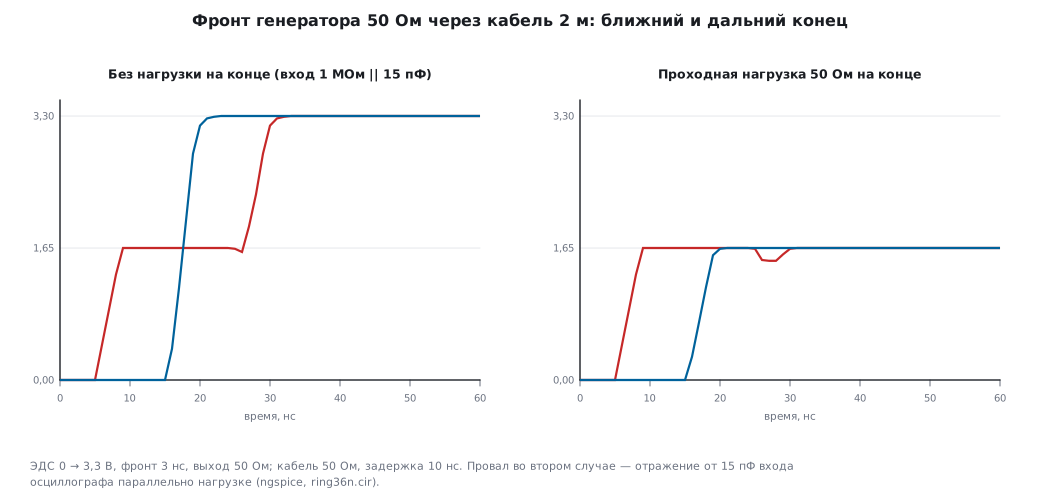
| point | unterminated | with 50 Ω termination |
|---|---|---|
| far end, final | 3.30 V, no overshoot | 1.65 V |
| far end, 10…90 % edge | 3.37 ns | — |
| near end | 1.65 V shelf for 20.7 ns, then 3.30 V | 1.65 V, dip to 1.49 V |
The far end is clean: the reflection from the open end comes back and is absorbed in the generator's 50 Ω. But at the generator there is a step: a shelf exactly at half, 1.65 V, for exactly as long as the wave takes to go there and back. Half of 3.3 V is right around a CMOS input threshold: a board connected at the generator through the tee sees an edge crawling slowly through the threshold, and a counter without hysteresis may count two. With a 50 Ω termination there is no step, but the amplitude is half: switch Imped on the generator to Load 50 Ω and set HighL 3.3 V again (36н.2).
Your own 3 ns edge on a DHO914/DHO924 screen (≤2.8 ns per the datasheet, p. 9) stretches to about 4.10 ns, on the 250 MHz models (≤1.4 ns) to 3.31 ns (adding as in 36а.3).
Typical mistake. Putting the 50 Ω termination at the generator instead of the far end: that is not a match but a divider, and the reflection stays. And do not mistake the shelf at the near end for a "bad generator".
36н.10 Task 9: two channels with a phase shift
Goal. Check how the oscilloscope measures phase and delay, and at the same time measure its own channel and cable skew.
Connection. Generator CH1 → oscilloscope CH1, CH2 → CH2; cables of equal length.
Generator. Both channels Sine, Freq 1 MHz, Ampl 1 Vpp, Imped HighZ; CH2 Phase 90° (from −360 to 360°, step 0.01° — DG guide p. 40). Then press Align Phase: without it the channel phases are not tied to each other, and the oscilloscope shows a random shift (DG guide p. 101). To change the frequency of both at once — Coupling → Freq Cpl, Ratio 1; the shift is held by Phase Cpl, Offset 90° (DG guide p. 98–99).
Oscilloscope. CH1 and CH2 at 200 mV/div, 200 ns/div, Edge trigger on CH1; Measure → Phase(r-r) and Delay(r-r), source A — CH1, B — CH2 (DHO guide p. 153–154).
What you should get. A 90° shift at 1 MHz is a delay of 250 ns. Sign: on the DHO900 the delay is negative if edge A comes after edge B (DHO guide p. 153); which phase sign the DG900 Pro treats as "leading" the DG guide does not say — check on your own bench. Second experiment: both channels at the same phase, frequency 10 MHz. The DHO900 channel-to-channel difference is typically up to 2 ns (datasheet p. 11), at 10 MHz that is 7.2°; an extra 20 cm of cable (5 ns/m, as in 36к.5) adds another 3.6°. The generator phase step of 0.01° at 10 MHz is 2.78 ps: the generator sets it more finely than the oscilloscope can resolve. Skew is removed with the channel delay adjustment, up to ±100 ns (datasheet p. 11).
Typical mistake. Changing the frequency and not pressing Align Phase again. The second is measuring at 1 kHz: 2 ns there is 0.0007°, the skew is invisible, and it seems there is none.
36н.11 Task 10: modulation and its spectrum on the FFT
Goal. Look at AM and FM in the spectrum and at the same time check the oscilloscope FFT on a signal with known components (how to read the FFT — 36е.21, 36е.22). The DG900 Pro can do AM, FM, PM, ASK, FSK, PSK, PWM and SUM, with an internal signal or an external one through [AUX IN/OUT] (DG guide p. 56).
Connection. Generator CH1 → oscilloscope CH1.
Generator. Sine, Freq 100 kHz, Ampl 1 Vpp, Imped HighZ. Output Mode → Mod. AM: Source Internal, Shape Sine, AM Freq 1 kHz, Depth 100 %, then 50 % (modulation frequency from 2 mHz to 1 MHz, depth from 0 to 120 % — DG guide p. 58). FM: FM Freq 1 kHz, Freq Dev first 1 kHz, then 2.405 kHz (DG guide p. 60).
Oscilloscope. CH1, 200 mV/div, 2 ms/div — a 20 ms window, FFT resolution 50 Hz (36е.21). Math → FFT, source CH1, Hanning window (the default, datasheet p. 17), center 100 kHz, span about 10 kHz.
What you should get (model: FFT with Hanning, dB relative to the carrier or to an unmodulated sine of the same Ampl):
| signal | carrier | 1st sideband | 2nd sideband |
|---|---|---|---|
| AM, Depth 100 % | −6.02 dB to the sine | −6.02 dBc | — |
| AM, Depth 50 % | −6.02 dB to the sine | −12.04 dBc | — |
| FM, β = 1 | −2.32 dB | −7.13 dB | −18.79 dB |
| FM, β = 2.405 | −80.86 dB — gone | −5.69 dB | −7.29 dB |
The FM rows are Bessel functions: J0(1) = 0.7652, J1(1) = 0.4401; J0(2.405) ≈ 0 — the carrier vanishes, J1(2.405) = 0.5191. This is the classic deviation check: turn Freq Dev until the carrier disappears from the FFT, and the deviation will be 2.405 × the modulation frequency. Carson's bandwidth for the second case is 6.81 kHz.
Why the AM carrier is 6 dB lower. According to the DG guide, at 0 % depth the amplitude is half the set value, and at 100 % it is the full value (p. 58): Ampl is the peak of the envelope, and the carrier is its middle. The model with this interpretation gave −6.02 dB to a sine of the same Ampl at any depth.
Typical mistake. A 2 ms window (200 us/div): 500 Hz resolution, and the sidebands at ±1 kHz merge with the carrier. The window must be no shorter than several modulation periods.
36н.12 Task 11: noise and averaging
Goal. Pull a weak periodic signal out of noise with Average and understand why averaging sometimes "eats" the signal itself. The DHO900 has no High Res mode (36г.16) — what remains is Average, BW Limit and digital filters (36е.19).
Connection. Generator CH1 → oscilloscope CH1, generator CH2 → oscilloscope CH2.
Generator. CH1: Sine, Freq 1 kHz, Ampl 100 mVpp, Imped HighZ; Output Mode → Mod, type SUM, Waveform Noise — noise is added to the sine (SUM Ratio is its share relative to the sine amplitude, DG guide p. 68). CH2: Square, Freq 1 kHz, 3.3 Vpp — a clean trigger signal of the same frequency. How much noise a SUM Ratio "percentage" means and what bandwidth the noise has, the guide does not say: pick the Ratio so that the noise VRMS on the oscilloscope is about 20 mV.
Oscilloscope. CH1 — 20 mV/div, CH2 — 2 V/div; Edge trigger on CH2; Horizontal → Acquisition → Average, 16, then 256 (from 2 to 65536, powers of two — datasheet p. 12); 200 us/div.
What you should get (model: a 100 mVpp sine and 20 mV rms noise):
| averages | remaining noise | calculation σ/√N |
|---|---|---|
| 16 | 4.93 mV | 5.00 mV |
| 256 | 1.25 mV | 1.25 mV |
The DHO900 code step at 20 mV/div is 39.1 µV, so 256 averages are limited by noise, not by resolution. If you need an even smaller signal, the DG900 Pro has a 40 dB attenuator for 50 Ω, 1 W (RA5040K, DG guide p. 120): 1 mVpp on a 50 Ω load turns into 10 µV peak-to-peak.
Typical mistake. Triggering on the noisy CH1 itself. Model: level 0, arming below −10 mV (assumed): noise triggers the sweep at random phases, and after 256 averages 11.7 % of the sine amplitude remains. Average requires every record to start at the same phase of the signal — hence the trigger on the clean generator CH2.
36н.13 Task 12: everything together from Python — frequency response to CSV
Goal. Measure the frequency response of the RC network from 36н.3 point by point automatically: the generator steps through frequencies, the script reads the frequency, amplitudes and phase from the DHO900 and writes a table.
What we control. The DHO900 commands are real, from the programming
guide (*IDN? — p. 148, :CHANnel<n>:SCALe — p. 97,
:MEASure:ITEM? — p. 217–218, :SYSTem:ERRor? — p. 290,
:TIMebase:MAIN:SCALe — p. 315; how to write commands and parse replies —
36ж.15). The generator is worse off: the DG guide sends you for commands to a
separate DG800 Pro/DG900 Pro Programming Guide (p. 36, 117), and itself
gives only two commands for option keys and one for loading points
(p. 35–36, 83) — nothing for frequency or output. Until we have the programming
guide, we ask the generator only *IDN? — the common
IEEE 488.2 command — and write the reply into the CSV header. The generator itself
controls the frequency, in Step mode.
Connection. As in 36н.3: network input — CH1, output — CH2. Both instruments over USB or LAN; the generator VISA address is Utility → I/O → VISA Address (DG guide p. 107), the oscilloscope's — 36ж.15.
Generator. Sine, Ampl 1 Vpp, Imped HighZ. Sweep: Sweep Type Step, Step Num 31, Start 100 Hz, Stop 100 kHz, Sweep Time 62 s, Source Manual. The time per step is set by Sweep Time and Step Num (DG guide p. 71); for Log and Step the total time is no more than 500 s (p. 72–73). How exactly the steps are spaced — equally in frequency or logarithmically — the guide does not say, so the script does not rely on the spacing: it measures the frequency itself. Start the script, then press Trigger on the generator.
Oscilloscope. As in 36н.3, without Peak; the script picks the time base itself (three periods per screen) and the CH2 scale (the output takes about six divisions).
# sweep_log.py — АЧХ по шагам: DG900 Pro качает сам (Sweep, Step), DHO900 меряет по SCPI, итог — CSV
import csv, math, sys, time
import pyvisa

SCOPE, GEN, OUT = sys.argv[1], sys.argv[2], sys.argv[3]   # VISA-адреса и имя файла
DT = 0.25                     # с между опросами; шаг генератора должен быть в несколько раз длиннее
STEPS = 31                    # Step Num в меню Sweep генератора

rm = pyvisa.ResourceManager()
scope, gen = rm.open_resource(SCOPE), rm.open_resource(GEN)
for d in (scope, gen):
    d.timeout = 5000
    d.read_termination = d.write_termination = "\n"


def cmd(s):
    scope.write(s)
    err = scope.query(":SYSTem:ERRor?").strip()
    if int(err.split(",")[0]) != 0:
        raise RuntimeError(s + " -> " + err)


def meas(item, *src):
    v = float(scope.query(":MEASure:ITEM? %s,%s" % (item, ",".join(src))))
    return None if abs(v) > 9e36 else v       # 9.9E37 — измерение не получилось


ids = [scope.query("*IDN?").strip(), gen.query("*IDN?").strip()]   # у генератора — только IEEE 488.2
rows, last, same = [], None, 0
with open(OUT, "w", newline="") as fh:
    w = csv.writer(fh)
    w.writerow(["# " + ids[0]])
    w.writerow(["# " + ids[1]])
    w.writerow(["f_Hz", "vin_V", "vout_V", "gain_dB", "phase_deg"])
    while len(rows) < STEPS:
        f = meas("FREQuency", "CHANnel1")
        if f is None:
            time.sleep(DT)
            continue
        if last is None or abs(f - last) > 0.01 * last:      # генератор перешёл на новый шаг
            last, same = f, 0
            cmd(":TIMebase:MAIN:SCALe %.3e" % (3 / f / 10))     # три периода на экран
            time.sleep(DT)
            continue
        same += 1
        if same == 2:                                          # второй совпавший опрос — шаг устоялся
            vin, vout = meas("VPP", "CHANnel1"), meas("VPP", "CHANnel2")
            ph = meas("RRPHase", "CHANnel1", "CHANnel2")
            cmd(":CHANnel2:SCALe %.3e" % (vout / 6))           # выход занимает около 6 делений
            vout = meas("VPP", "CHANnel2")
            row = [round(f, 1), vin, vout, round(20 * math.log10(vout / vin), 2), ph]
            rows.append(row)
            w.writerow(row)
            print("%9.1f Hz %7.2f dB %7.1f deg" % (row[0], row[3], ph))
        time.sleep(DT)
What you should get. A run against the stub instruments (steps logarithmic, 2 s per step, virtual time): 31 rows in 63.75 s, not a single error in the queue. A few output rows:
| frequency | gain | phase |
|---|---|---|
| 100 Hz | −0.00 dB | 1.7° |
| 3162.3 Hz | −2.72 dB | 43.0° |
| 3981.1 Hz | −3.77 dB | 49.6° |
| 100000 Hz | −29.41 dB | 88.1° |
The 3386.3 Hz cutoff lies between two steps — the Mark in 36н.3 or more steps gives it more precisely. The phase is positive: the output comes later than the input, and the DHO900 Delay(r-r) is positive when edge B comes after A (DHO guide p. 153).
Typical mistake. A generator step shorter than two polls plus the time base change: the script will miss frequencies. And a CH2 scale left at 1 V/div: at −29 dB the amplitude is 34 mV — that is 17 codes, and the gain jumps around.
36н.14 Pitfalls
Twice as much or half as much. The generator Imped does not match the real load. HighZ into a 1 MΩ input is right; with a feed-through 50 Ω termination — Load 50 Ω (36н.2).
The board got 20 Vpp. Load Last = Last restored yesterday's setting. Output first to the oscilloscope, board input through 1.5 kΩ (36н.1).
The frequency response "squashed" with a linear sweep. Up to the 3386.3 Hz cutoff is 3.29 % of the sweep time. Log only (36н.3).
The firmware sees 1 kHz while 9 kHz is applied. Aliasing at 10 kHz sampling; a filter in front of the ADC, not in the firmware (36н.4).
The delay tail cannot be caught. The generator frequency is a multiple of the firmware task rate: with crystals differing by 20 ppm, 79.2 % of ten-second attempts show no tail. A non-multiple frequency — 1013 Hz (36н.5).
Capture shows garbage at 1 kHz. A 16-bit overflow with a 1/72 MHz tick: below 1098.6 Hz — only with a prescaler (36н.6).
The interrupt counts 668 out of 1000. The handler cannot keep up at 1 MHz; count with a timer clocked from the input (36н.7).
The counter at the generator counted extra. A 1.65 V shelf at the near end of an unterminated cable — 20.7 ns at the threshold (36н.9).
The phase between channels is random. Align Phase was not pressed (36н.10).
The AM carrier is 6 dB lower than expected. On the DG900 Pro, Ampl is the peak of the envelope (36н.11).
Averaging erased the signal. Triggering on the noisy channel: 11.7 % of the amplitude after 256 records; trigger on the clean CH2 (36н.12).
36н.15 Summary
- A generator output is 50 Ω in series and an EMF up to ±10 V; not a power supply. Board input through 1.5 kΩ, first switch-on into the oscilloscope.
- Imped (HighZ or Load) changes only the number on the generator screen; the DG900 Pro defaults to HighZ. The DHO900 has no external trigger input — the generator Sync goes to a channel.
- A Log sweep with a Mark gives a frequency response on any oscilloscope: Sync falls at the frequency you need, and Peak keeps the envelope.
- The generator checks firmware: the ADC and aliasing, EXTI delay (a frequency that is not a multiple of the firmware tasks), capture (the oscilloscope with ±25 ppm is the reference), burst counting (an interrupt loses edges above its own rate).
- An unterminated cable is clean at the far end and gives a shelf at the generator; a 50 Ω termination removes the shelf and halves the amplitude.
- Align Phase after every frequency change; channel skew is visible at 10 MHz, not at 1 kHz.
- AM and FM are ready-made references for the FFT: sidebands −6.02 dBc at 100 %, the FM carrier vanishes at β = 2.405.
- Average works only with a trigger on a clean signal.
- Automation: the DHO900 through its own SCPI commands, the generator for now
only
*IDN?and its own Step; full control needs the DG900 Pro Programming Guide.
Next: part VI, section 37 "IoT applications" — network modules, stacks and data exchange with a server.