 Embedded HandbookApps
82. Indication on a prototype: PWM, RGB, shift registers
Indication is the first debugging tool and the main way for a device to tell the user something. On a prototype it is an LED with smooth brightness, an RGB LED, a seven-segment display driven through a shift register. How this works on STM32 was covered in detail earlier: PWM and the eye in section 57, shift registers, multiplexed displays and addressable LEDs in section 22. Here is the view from a prototype: what the familiar Arduino functions do, where typical examples get it wrong and what it all turns into on STM32.
The shift register model, the digit table and the multiplexing were checked by a test
on a PC; the STM32 code was built with armclang.
Terms used in the documentation
Term Meaning PWM, duty cycle pulse-width modulation, the fraction of the period the output is on perceived brightness, gamma correction brightness as the eye sees it, and its compensation common anode / common cathode the shared pin of the LEDs goes to the supply / to ground seven-segment display a digit made of seven segments multiplexing, refresh rate lighting digits in turn, how often each is refreshed serial-in parallel-out shift register a register loaded bit by bit, with parallel outputs storage register, latch the output register that holds the value output enable the input that switches the outputs on bit order, MSB / LSB first which bit is sent first, the most / least significant daisy chain registers connected one after another
82.1 What to display with
| Device | Pins | Note |
|---|---|---|
| LED | 1 | current through a resistor (section 49.3), brightness by PWM |
| RGB LED | 3 | three PWM channels, different resistors (82.3) |
| seven-segment display, 4 digits | 32 directly, 12 multiplexed, 3 through registers | 82.5 and section 22.3 |
| LED matrix | as for a display | the same multiplexing |
| addressable strip | 1 | its own protocol and a separate supply (section 22.4) |
| graphic display | SPI or I²C | section 18.8 |
| piezo buzzer | 1 | sound is indication too: the frequency comes from a timer (section 13) |
82.2 PWM: brightness without a DAC
The Uno has no DAC, and neither does the F103C8 (section 15). Smooth brightness comes from pulse-width modulation: the pin is switched on and off at a constant frequency, and what changes is the fraction of time it is on.
The duty cycle D is the pulse width divided by the period: from 0 to 1. In strict Russian terminology the term "skvazhnost" (duty factor) is the inverse quantity, the period divided by the pulse width: at D = 0.25 the duty factor is 4. In everyday use, including in section 57, the duty cycle itself is often called by that name — it is easy to tell them apart: the duty factor in the strict sense is always greater than one.
For an LED the current is set by a resistor, so the brightness is proportional to D
(section 57.3). The analogWrite(pin, 0…255) function in Arduino is 8-bit
PWM. On STM32 a timer allows more: at 72 MHz 16-bit PWM runs at
1.1 kHz, 12-bit at 17.6 kHz (the trade-off of frequency for resolution is in
section 57.1).
/* TIM2, канал 1 на PA0: 16-битный ШИМ, 72 МГц / 65 536 ≈ 1,1 кГц */
void pwm_init(void)
{
    RCC->APB2ENR |= RCC_APB2ENR_IOPAEN;
    RCC->APB1ENR |= RCC_APB1ENR_TIM2EN;
    GPIOA->CRL = (GPIOA->CRL & ~0xFu) | 0xBu;           /* PA0: альтернативная функция */
    TIM2->PSC = 0;
    TIM2->ARR = 65535;
    TIM2->CCMR1 = TIM_CCMR1_OC1M_2 | TIM_CCMR1_OC1M_1 | TIM_CCMR1_OC1PE;   /* ШИМ, режим 1 */
    TIM2->CCER = TIM_CCER_CC1E;
    TIM2->CR1 = TIM_CR1_ARPE | TIM_CR1_CEN;
}

void pwm_set(uint16_t duty)
{
    TIM2->CCR1 = duty;
}
Why so many bits. The eye perceives brightness nonlinearly, and most strongly at the bottom of the scale. The first step of 8-bit PWM is 0.39 % of the current, but on the CIE perceived brightness scale it is already 3.5 %: a smooth turn-on starts with a step. With 16-bit PWM the first step is 0.014 %.
Correcting for the eye. The cheapest approximation is to square the desired brightness:
/* яркость «на глаз» 0…255 → 16-битное заполнение ШИМ: квадрат вместо прямой */
uint16_t bright_to_duty(uint8_t b)
{
    return (uint16_t)((uint32_t)b * b * 65535u / 65025u);
}
The scale is monotonic, from 0 to 65535, and the first step is 1. The middle of the scale gives 25 % duty; the exact exponent 2.2 from section 57.3 gives 21.8 %. For an indicator the square is enough; for lighting a table is better.
⚠️ A smooth ramp with
delay()— a loop of 256 steps of 20 ms — ties up the program for five seconds. On STM32 the brightness step is done from a timer interrupt or by DMA (section 9), and the program only sets the target.
82.3 The RGB LED
Three LEDs in one package with a common pin.
- Common cathode — the common pin goes to ground, the channels light up with a one: the duty cycle is direct.
- Common anode — the common pin goes to the supply, the channels light up with a zero:
the duty cycle is inverted, 0 means full brightness. The simplest way is to
turn on the timer channel's polarity inversion — the
CCxPbit inTIMx->CCER(for the first channelTIM_CCER_CC1P) — rather than recompute the values.
The three channels of one timer (CH1–CH3) share one period — the colors are guaranteed
to have the same frequency.
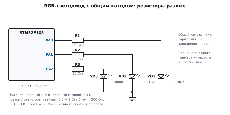
The resistors are different. The red die drops about 2 V, the green and blue ones about 3 V. With a 3.3 V supply at 5 mA the red one needs a 260 Ω resistor, the blue one only 60 Ω. And for blue this is unreliable: only 0.3 V is left across the resistor, and a ±0.1 V spread in the drop from one part to another gives a current from 3.3 to 6.7 mA — a factor of two. An RGB circuit carried over from a 5 V board gives a different color at 3.3 V; for blue and green a 5 V supply through a switch (section 52) or a current source is better.
82.4 The shift register: shiftOut and SPI
The 74HC595 takes bits one at a time and puts them out on eight outputs
(section 22.1). In Arduino you fill it with the function
shiftOut(dataPin, clockPin, bitOrder, value) — this is a software transfer,
bit by bit. On STM32 hardware SPI does the same: MOSI is the data,
SCK is the shift clock, and the latch is an ordinary pin.
void hc595_send(uint8_t v)
{
    GPIOA->BRR = 1u << 4;                   /* RCLK — низкий */
    SPI1->DR = v;
    while (!(SPI1->SR & SPI_SR_TXE))
        ;
    while (SPI1->SR & SPI_SR_BSY)           /* дождаться последнего бита */
        ;
    GPIOA->BSRR = 1u << 4;                  /* фронт RCLK — байт на выходы */
}
With an SPI prescaler of 8 (9 MHz from 72) a byte goes out in 0.89 µs. By default SPI
sends the most significant bit first — like shiftOut(…, MSBFIRST, …).
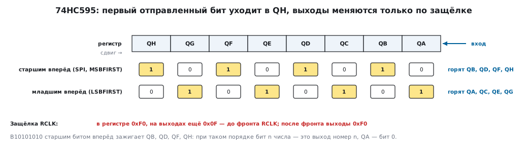
Which outputs light up. On each clock the bit at the input enters QA,
and the contents shift towards QH. So the first bit sent
ends up in QH, and the last one in QA:
| Sent | Order | Lit |
|---|---|---|
B10101010 |
MSB first | QB, QD, QF, QH |
B10101010 |
LSB first | QA, QC, QE, QG |
Examples often say that B10101010 with the most significant bit first
lights QA, QC, QE, QG — the register model shows the opposite.
The rule is simple: with MSB first, bit n of the number is output number n
(QA is bit 0).
The latch. Until a rising edge arrives on RCLK, the outputs hold the old value:
in the test the outputs showed 0F, F0 was shifted into the register — the outputs
stayed 0F and became F0 only after the latch. That is why intermediate
states are not visible.
⚠️ PWM through
OEis inverted. The output enable inputOEis active low. If you feed PWM into it to change the brightness of all eight outputs at once, the higher the duty cycle, the dimmer they get: the outputs are on whileOEis low.⚠️ Current through one chip. The
74HC595has a limit on the total current through its supply pins — 70 mA per the datasheet. Eight LEDs at 20 mA is 160 mA, beyond the limit; at 8 mA it is 64 mA, within the limit.
82.5 Multiplexed display
Four digits of eight segments driven directly take 32 pins. If you light
the digits in turn, 12 are enough: the eight segment lines are shared, and four
pins select the digit. With two 74HC595 chips it is three pins for everything.
Digits come from a table where bit 0 is segment a and bit 6 is g:
const uint8_t seg7[10] = {0x3F, 0x06, 0x5B, 0x4F, 0x66, 0x6D, 0x7D, 0x07, 0x7F, 0x6F};
The multiplexing is called from a timer interrupt (section 13):
typedef struct {
    uint8_t digits[4];  /* что показать, по разрядам */
    uint8_t pos;        /* какой разряд горит сейчас */
} disp_t;

/* Вызов из прерывания таймера. Вернёт сегменты, номер разряда — в *digit. */
uint8_t disp_tick(disp_t *d, uint8_t *digit)
{
    *digit = d->pos;
    uint8_t seg = seg7[d->digits[d->pos] % 10];
    d->pos = (uint8_t)((d->pos + 1) & 3);
    return seg;
}
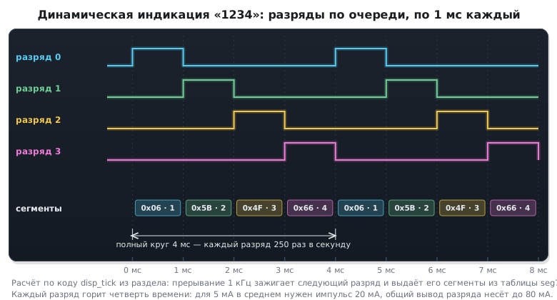
For "1234" the test showed digits 0, 1, 2, 3 in turn with codes 06,
5B, 4F, 66 and a return to digit zero. The state is 5 bytes.
The order in the handler. Turn off the current digit → set the segments
of the next one → turn on the next digit. If you change the segments while a digit
is lit, it will briefly show someone else's digit, and faint "ghosts" will appear
on the neighboring digits. With two 74HC595 chips it is the same: first shift in
and latch a byte with the digits turned off, then the new segments
and the new digit.
Four numbers that decide the circuit:
- frequency: switching at 1 kHz gives each digit 250 refreshes per second and 1 ms of light each (sections 22.3 and 57.4);
- brightness: a digit is lit a quarter of the time, so for 5 mA on average you need a 20 mA pulse — within what the display allows;
- common pin current: with a 20 mA pulse per segment, eight segments make 160 mA through the digit pin, six times the pin limit of the F103 (section 62.6). Select the digit with a transistor, not directly with a microcontroller pin;
- segment register current: through the
74HC595it is the same 8 × 20 mA = 160 mA with a chip limit of 70 mA (82.4). Either a smaller pulse (8 mA per segment — 64 mA, a dimmer display), or the segments are driven by a separate driver — a transistor array or a shift register with high-current outputs.
82.6 Pitfalls
A smooth LED turn-on starts with a jump. 8-bit PWM: the first step is 3.5 % of perceived brightness.
Brightness changes "unevenly". There is no correction for the eye.
The RGB LED gives the wrong color. The same resistors on all channels, or a 3.3 V supply for blue and green.
A common-anode RGB LED works "backwards". The duty cycle is inverted.
The wrong register outputs light up. The bit order is mixed up: with MSB first, bit n is output n.
The display flickers with intermediate values. The latch is toggled before the transfer ends, or not toggled at all.
PWM on OE works backwards. OE is active low.
The shift register gets hot. The total current of eight LEDs is above the chip's limit.
The multiplexed display is dim. Each digit is lit a quarter of the time — you need a higher pulse current.
Faint "ghosts" of other digits on the neighboring digits. The segments were changed while the digit was lit: first turn the digit off, then change the segments (82.5).
The microcontroller pin on the common line of a digit has failed. 160 mA through one pin; you need a transistor.
82.7 Summary
- The duty cycle is the pulse width over the period, from 0 to 1; the duty factor in the strict sense is the inverse quantity.
analogWriteis 8-bit PWM; an STM32 timer gives 16 bits at 1.1 kHz at 72 MHz. The first 8-bit step is 3.5 % of perceived brightness.- The square of the desired brightness is a cheap correction for the eye: the middle of the scale is 25 % duty versus 21.8 % for the exponent 2.2.
- An RGB LED needs different resistors; at 3.3 V blue and green have almost no margin; a common anode inverts the duty cycle.
- On STM32 hardware SPI replaces
shiftOut; with MSB first, bit n of the number is output n of the register; the latch hides intermediate states;OEis active low. - Multiplexing: 12 pins instead of 32, 1 kHz for four digits, a pulse current four times the average, the digit through a transistor.
Next: section 83 "I²C and SPI on a prototype: a sensor and a display".