 Embedded HandbookApps
198э. Mini-project: a temperature sensor over Bluetooth LE on the P-NUCLEO-WB55 — two cores, IPCC and a custom GATT service
Bluetooth LE has already appeared in the handbook three times. In section 158 a GATT server was brought up on the ESP32 with the NimBLE stack: there the stack and the program live on one processor. In section 189 BLE was examined from the phone side — MTU, one write at a time, permissions. In section 94б the STM32WB55 turned up inside the Flipper Zero, but only as "a processor with a radio": what is inside the stack and how to reach it was not covered there.
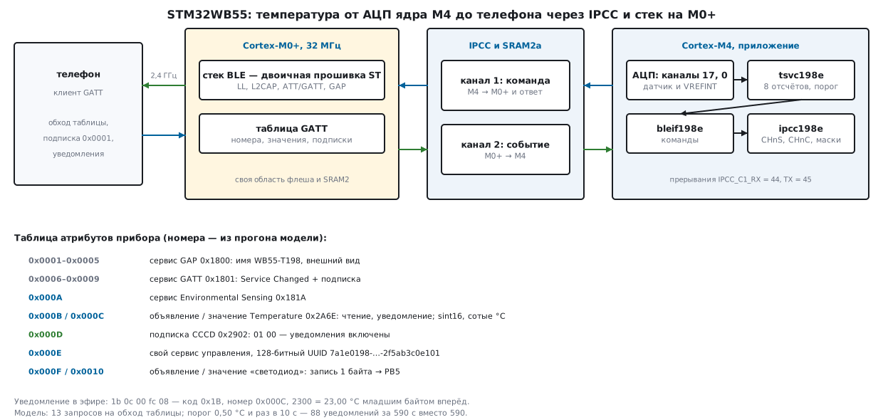
Here is a complete device on a single P-NUCLEO-WB55 board: a temperature sensor that a phone finds by name, reads and subscribes to. The main difference from the ESP32 is that the STM32WB55 has two cores. The program lives on a Cortex-M4, the Bluetooth stack on a separate Cortex-M0+, and they talk through shared memory and the IPCC block. The section is about how this conversation works, what a custom GATT service looks like and what exactly goes over the air when a phone walks the device's table.
All runs in this section were done on a PC. The code of the M4 core — the service, the commands to the radio core, the IPCC driver — is real, the same code that is built for the STM32WB55. Underneath it, instead of the chip, there are three models: the IPCC block according to the reference manual, a radio core with its own GATT table and a "phone" — a GATT client that logs every ATT packet. The exchange between the cores in the model is its own simple format, not the format of the ST library: what takes its place in a real device is shown in 198э.4.
Prerequisites: reference manual RM0434 (rev. 12) — IPCC, booting the second
core, flash and RAM, the ADC and the temperature sensor; datasheet DS11929 (rev. 16) —
frequencies, memory, calibrations; the board description DB3659 and the board files
stm32wbxx_nucleo.h from the Keil STM32WBxx_DFP 1.4.0 pack; the CMSIS header
stm32wb55xx.h and the linker template stm32wb55xx_flash_cm4.ld from the same pack.
How the conversation with the ST stack works in a live device is taken from the Flipper
Zero sources, github.com/flipperdevices/flipperzero-firmware (commit 7f0b6e1,
GPL-3.0), directory targets/f7/ble_glue. ATT codes, type numbers and
advertising fields were checked against the NimBLE headers (github.com/espressif/esp-nimble,
commit a9a4c70, Apache-2.0) and ESP-IDF v5.4.1 (commit 4c2820d, Apache-2.0).
The PC build is gcc 12.2.0 in stm-sys:1, the firmware is
arm-none-eabi-gcc 12.2.1 in stm-arm:1. STM32WB registers are in appendix A17.
Terms used in the documentation
Term Meaning CPU1, CPU2 the M4 core with the program and the M0+ core with the radio stack wireless stack, FUS (Firmware Upgrade Service) the radio core firmware from ST and its installer IPCC, channel, occupied / free the inter-processor communication block, a channel, "occupied" / "free" Simplex, Half-duplex a one-way channel; command and response in the same buffer mailbox, shared memory (SRAM2a) the shared memory where the messages lie ACI, HCI commands to the ST stack and the standard Bluetooth controller interface GATT, ATT, attribute handle the table of services, the attribute protocol, the attribute number CCCD (0x2902) the subscription descriptor: the client writes 01 00 to receive notifications notification / indication a notification without acknowledgement / an indication with acknowledgement Environmental Sensing (0x181A), Temperature (0x2A6E) the standard environmental sensing service and temperature characteristic advertising, AD type advertising — packets sent before a connection; an advertising field
198э.1 The board and the plan
The P-NUCLEO-WB55 is a set of two boards (description DB3659): a Nucleo-68 with an STM32WB55RG in a VFQFPN68 package and a small USB dongle with an STM32WB55CG. Only the Nucleo is needed here. On it:
| What | Where | Source |
|---|---|---|
| three LEDs | LED1 blue — PB5, LED2 green — PB0, LED3 red — PB1 | stm32wbxx_nucleo.h |
| three buttons and reset | SW1 — PC4, SW2 — PD0, SW3 — PD1 | stm32wbxx_nucleo.h |
| console | USART1: TX — PB6, RX — PB7, AF7 (the board's COM1) | stm32wbxx_nucleo.h |
| programmer | ST-LINK/V2-1: mass storage, virtual COM port, debugging | DB3659 |
| antenna | on the board, or an SMA connector for one | DB3659 |
| power | from the ST-LINK USB or external, a CR2032 holder | DB3659 |
The documents contain no board schematic — only the description and the board files, so
what goes to which pin is taken from stm32wbxx_nucleo.h and was not checked
against the board itself.
How the WB55 differs from the handbook's reference boards — the BluePill with the F103 and the Discovery with the F407:
| F103 | F407 | STM32WB55RG | |
|---|---|---|---|
| program core | Cortex-M3, 72 MHz | Cortex-M4F, 168 MHz | Cortex-M4F, up to 64 MHz |
| second core | none | none | Cortex-M0+, 32 MHz, radio only |
| flash / RAM | 64 KB / 20 KB | 1 MB / 192 KB | 1 MB / 256 KB, part of it taken by the radio core |
| radio | none | none | 2.4 GHz: Bluetooth LE 5.4 and 802.15.4 |
The WB55 core frequencies and memory are from DS11929. Radio: sensitivity −96 dBm for BLE at 1 Mbit/s, output power up to +6 dBm in 1 dB steps (DS11929, first page) — not measured in this section.
What the device does:
- every 125 ms the ADC measures the chip temperature sensor and the reference voltage VREFINT; once a second the average of 8 samples is computed;
- it advertises itself with the name
WB55-T198and the service number 0x181A; - it holds an Environmental Sensing service with a Temperature characteristic (read and notifications) and a custom service with an "LED" (writing one byte lights LED1);
- it sends a notification not every second, but when the temperature has moved by the threshold or nothing has been sent for a long time (198э.7).
The chip sensor was chosen so that nothing needs soldering: it measures the heating of the chip itself, not the air. For a real weather station it is replaced by an external sensor, as in 198м — the rest of the device does not change.
198э.2 Two cores: who is responsible for what
The stack is someone else's firmware. The M0+ core runs a binary firmware from ST;
there are no sources for it. The Flipper Zero selects the light
variant in fbt_options.py:
COPRO_STACK_BIN = "stm32wb5x_BLE_Stack_light_fw.bin"
Besides the stack the radio core has the FUS installer — it installs, deletes and
updates the stack. The M4 core learns which one is running now from the first event
after start-up: in ble_glue.c the Flipper compares the field sysevt_ready_rsp with
WIRELESS_FW_RUNNING (the stack is running) and FUS_FW_RUNNING (the installer
is running). The installer commands — SHCI_C2_FUS_FwUpgrade,
SHCI_C2_FUS_FwDelete, SHCI_C2_FUS_StartWs — are there too.
Secure memory. The stack lies in the upper part of the flash, and the M4 core cannot
see it. Where the secure part begins is given by the option byte field SFSA —
the number of the first 4-kilobyte page (RM0434, 3.4.1, address 0x1FFF 8070).
RAM is arranged the same way: the fields SBRSA and SNBRSA (address 0x1FFF 8078) set
the start of the secure parts of SRAM2a and SRAM2b in 1 KB steps. What this looks like from
the side of the Flipper firmware is covered in 94б.2.
Memory for two. According to DS11929 the WB55 has three RAM blocks: SRAM1 of up to 192 KB from
address 0x2000 0000, SRAM2a — 32 KB from 0x2003 0000 (retained in Standby)
and SRAM2b — 32 KB from 0x2003 8000. The messages between the cores lie in SRAM2a.
ST's linker template for the M4 core (stm32wb55xx_flash_cm4.ld) divides
memory like this:
| Region | Start | Size | What is there |
|---|---|---|---|
FLASH |
0x0800 0000 | 512K | the M4 program; above it — room for the radio core stack |
RAM1 |
0x2000 0008 | 0x2FFF8 | M4 data and stack |
RAM_SHARED |
0x2003 0000 | 10K | MAPPING_TABLE, MB_MEM1, MB_MEM2 — memory shared with the M0+ |
How does the radio core find this table? The option bytes contain the field
IPCCDBA (address 0x1FFF 8068): the offset of the buffer start in SRAM2 in double
words. Its factory value is 0 (RM0434, 3.4.1), that is, the start of
SRAM2a — exactly where the template places MAPPING_TABLE. That is why in custom
linker scripts this section is kept first.
Starting the second core. After reset the M0+ is halted. It starts only
when the M4 core sets the C2BOOT bit in PWR_CR4 (RM0434, 2.4). Before that the Flipper
sends an event — in case the bootloader has already set the bit
and a repeated write would do nothing (a comment in hw_ipcc.c). The section's
own function does the same:
void cpu2_boot(void)
{
    __SEV();
    __WFE();
    PWR->CR4 |= PWR_CR4_C2BOOT;
}
The start-up order in a live device — from the Flipper's ble_glue.c and ble_app.c:
the shared table and the queues (TL_Init, shci_init, TL_MM_Init,
TL_Enable), starting the core, waiting for the "ready" event, configuring the stack with
SHCI_C2_BLE_Init, and only then GAP, GATT, the custom services and advertising.
The stack parameters are one structure; the Flipper checks its size with
_Static_assert(sizeof(SHCI_C2_Ble_Init_Cmd_Packet_t) == 58, …) with
a note that the fields were checked against stack v1.17.3. How much of everything the
Flipper reserves (app_conf.h):
| Parameter | Value | What it is |
|---|---|---|
CFG_BLE_NUM_LINK |
2 | simultaneous connections |
CFG_BLE_NUM_GATT_SERVICES |
8 | services; per the comment, "2 plus your own" — the stack adds GAP and GATT itself |
CFG_BLE_NUM_GATT_ATTRIBUTES |
68 | attributes excluding service declarations; "9 plus your own" |
CFG_BLE_MAX_ATT_MTU |
256 + 128 + 16 + 8 + 4 + 2 = 414 | the largest MTU |
CFG_BLE_ATT_VALUE_ARRAY_SIZE |
1344 | bytes for all values |
By the same rules our device needs 2 + 2 = 4 services and 9 + 5 = 14 attributes: the temperature has a declaration, a value and a subscription, the LED a declaration and a value.
198э.3 IPCC: six flags in each direction
IPCC does not transfer data. It only raises flags: "I have put a message"
and "I have taken it". The messages themselves lie in shared memory, and the block
does not know where exactly (RM0434, 37.1). There are six channels in each direction, and each
channel has a flag CHnF: 1 — occupied, the receiver may read the data, 0 —
free, the sender may write.
The registers on the M4 core side (stm32wb55xx.h: IPCC_C1 starts at
IPCC_BASE, IPCC_C2 is 0x10 further on):
| Register | Offset | Bits | What it does |
|---|---|---|---|
IPCC_C1CR |
0x000 | 16 TXFIE, 0 RXOIE |
enable the "free" and "occupied" interrupts |
IPCC_C1MR |
0x004 | 21:16 CHnFM, 5:0 CHnOM |
per-channel masks; after reset 0xFFFF FFFF — everything masked |
IPCC_C1SCR |
0x008 | 21:16 CHnS, 5:0 CHnC |
occupy your own channel; free a channel from the M0+; reads as 0 |
IPCC_C1TOC2SR |
0x00C | 5:0 CHnF |
flags of the M4 → M0+ channels |
IPCC_C2TOC1SR |
0x01C | 5:0 CHnF |
flags of the M0+ → M4 channels |
The IPCC registers may be written only as 32-bit words: a byte or a
half-word does not work and does not even cause a bus error (RM0434, 37.4).
The M4 core has two interrupts: IPCC_C1_RX_IRQn = 44 ("some channel from the M0+
is occupied and not masked") and IPCC_C1_TX_IRQn = 45 ("one of my channels
has become free and is not masked").
A channel has two modes (RM0434, 37.3.2–37.3.3):
- simplex — the sender puts the data and sets
CHnS; the receiver reads and clears the flag withCHnC; this is how events from the M0+ travel in the model; - half-duplex — the receiver, having read the command, writes the response into the same
buffer and only then clears the flag; for the sender "the channel is free" also
means "the response is ready". This is how commands travel in the model. The Flipper does the same:
HW_IPCC_Tx_Handlerhandles the response of the system channel on the "free" interrupt.
Sending a command and waiting for the response — ipcc_cmd from ipcc198e.c:
int ipcc_cmd(const uint8_t *msg, uint8_t *rsp, unsigned rsp_max)
{
    unsigned len = 2u + msg[1];
    if (len > MSG_MAX)
        return -2;
    if (ipcc_hw_tx_flags() & CH_BIT(CH_CMD))
        return -1;                                       /* канал ещё занят: буфер трогать нельзя */
    memcpy(mem->cmd, msg, len);
    cmd_wait = 1;
    ipcc_hw_scr(CH_BIT(CH_CMD) << 16);                   /* CHnS: «занят» — у M0+ прерывание RX occupied */
    mr_set(0, CH_BIT(CH_CMD) << 16);                     /* открыть «свободен» (CHnFM = 0): это будет ответ */
    for (unsigned n = 0; cmd_wait; n++) {
        if (n >= IPCC_WAIT_MAX)
            return -3;                                   /* радиоядро молчит */
        ipcc_hw_wait();
    }
    unsigned rl = 2u + mem->cmd[1];
    if (rl > rsp_max || mem->cmd[0] != (msg[0] | RSP_FLAG))
        return -4;
    memcpy(rsp, mem->cmd, rl);
    return (int)rl;
}
The order matters: first the data into memory, then the flag. The "free" mask
is opened after the flag is set — otherwise the interrupt would fire at once, since
before CHnS the channel was free. The handlers of the two interrupts:
void ipcc_tx_isr(void)
{
    uint32_t mr = ipcc_hw_mr();
    uint32_t freed = ~ipcc_hw_tx_flags() & ~(mr >> 16) & 0x3Fu;
    if (freed & CH_BIT(CH_CMD)) {
        ipcc_hw_set_mr(mr | (CH_BIT(CH_CMD) << 16));     /* закрыть «свободен», иначе прерывание не кончится */
        cmd_wait = 0;
    }
}

void ipcc_rx_isr(void)
{
    uint32_t mr = ipcc_hw_mr();
    uint32_t busy = ipcc_hw_rx_flags() & ~mr & 0x3Fu;
    if (!(busy & CH_BIT(CH_EVT)))
        return;
    unsigned depth = evq_head - evq_tail;
    if (depth >= EVQ_LEN) {                              /* очередь полна: событие оставить в канале */
        ipcc_hw_set_mr(mr | CH_BIT(CH_EVT));             /* CHnOM = 1 — M0+ подождёт, ничего не теряется */
        return;
    }
    unsigned len = 2u + mem->evt[1];
    memcpy(evq[evq_head % EVQ_LEN], mem->evt, len > MSG_MAX ? MSG_MAX : len);
    evq_head++;
    if (depth + 1u > ipcc_evq_max)
        ipcc_evq_max = depth + 1u;
    ipcc_hw_scr(CH_BIT(CH_EVT));                         /* CHnC: забрали — канал свободен для M0+ */
}
In the handler an event is only copied into a queue of 8 messages, and the main loop processes it. The channel is freed at once, and the M0+ can put the next one. If the queue is full, the channel stays occupied, and the "occupied" interrupt is closed by the mask: the radio core waits until the main loop clears the queue, and the event is not lost.
The driver does not touch the registers directly: all accesses go through seven
ipcc_hw_* functions. On the chip they write to IPCC_C1->SCR and its neighbours
(ipcc_hw_wb198e.c), on the PC to the model (ipcc_model198e.c). In the
model an interrupt line is level-sensitive, as in the chip: while the condition holds,
the handler is called again.
Experiments with the IPCC model:
| What | Result |
|---|---|
| application start-up: 5 commands to the radio core | 5 responses, 10 model steps, 5 handler calls |
| 3 commands in a row through the driver | 3 of 3 executed |
| 3 commands in a row "head-on", without checking the flag | 1 of 3 executed — the last one, value 0x0912 |
| the "free" handler does not close the mask | the command is executed, but 1000 calls per step — a "storm"; and so on each of the next 10 steps |
| 12 events in a row, the main loop busy | 8 in the M4 queue, 12 waiting at the M0+, 9 delivered; after processing — 12 of 12, 0 lost |
| the radio core is not started | ipcc_cmd returned −3 after 1000 waits |
The "head-on" send from the experiment — never write it like this:
        for (int i = 0; i < 3; i++) {
            uint8_t m[7] = {CMD_UPDATE, 5, (uint8_t)ts.ch_temp, (uint8_t)(ts.ch_temp >> 8), 2, (uint8_t)(0x10 + i), 0x09};
            memcpy(shm.cmd, m, sizeof m);              /* не глядя на CH1F */
            ipcc_hw_scr(CH_BIT(CH_CMD) << 16);
        }
Writing CHnS again to an already occupied channel does nothing: there is one flag.
The radio core saw one command and read the buffer, which by
then held the last one. Two commands vanished without a trace and without an error.
198э.4 Commands to the radio core: our own model and what ST has in its place
The application needs four things from the radio core: create a service, create
a characteristic, update a value and turn on advertising. In the opposite direction
come four events: connected, disconnected, the client wrote an attribute,
the MTU was agreed. In the model these are our own messages (msg198e.h): a code byte,
a length byte, parameters least significant byte first. ST has ACI commands and
HCI events on top of its own transport library. The correspondence — from
what the Flipper calls and handles:
Model (msg198e.h) |
ST stack, as in the Flipper | Where in the Flipper |
|---|---|---|
CMD_ADD_SERVICE |
aci_gatt_add_service |
furi_ble/gatt.c |
CMD_ADD_CHAR |
aci_gatt_add_char (+ aci_gatt_add_char_desc) |
furi_ble/gatt.c |
CMD_UPDATE |
aci_gatt_update_char_value |
furi_ble/gatt.c |
CMD_ADVERTISE |
aci_gap_set_discoverable |
gap.c |
EVT_CONNECTED |
HCI_LE_CONNECTION_COMPLETE_SUBEVT_CODE |
gap.c |
EVT_DISCONNECTED |
HCI_DISCONNECTION_COMPLETE_EVT_CODE |
gap.c |
EVT_ATTR_WRITTEN |
ACI_GATT_ATTRIBUTE_MODIFIED_VSEVT_CODE |
services/serial_service.c |
EVT_MTU |
ACI_ATT_EXCHANGE_MTU_RESP_VSEVT_CODE |
gap.c |
The application (tsvc198e.c) calls only bleif_* and does not know what lies beneath them.
To move it onto the ST stack, only bleif198e.c is rewritten — the ACI
functions themselves come from the STM32CubeWB package (the Flipper includes it as
lib/stm32wb_copro, version 1.20.0 in fbt_options.py). The section was not built
with the ST package.
The Flipper has an important detail about attribute handles. The write handler in
serial_service.c tells where the client wrote like this:
            if(attribute_modified->Attr_Handle ==
               serial_svc->chars[SerialSvcGattCharacteristicRx].handle + 2) {
That is, aci_gatt_add_char returns the handle of the characteristic declaration,
the value is one handle further, the descriptor two. The model assigns handles
the same way, and the application uses the same rule: the temperature subscription is
ts.ch_temp + 2, the LED value is ts.ch_led + 1.
tsvc_init creates the services:
int tsvc_init(uint16_t thr_c100, uint16_t heartbeat_s)
{
    int r = 0;
    memset(&ts, 0, sizeof ts);
    ts.thr = thr_c100;
    ts.heartbeat = heartbeat_s;
    ts.mtu = 23;
    r |= bleif_add_service(U_ESS, 2, 4, &ts.svc_ess);      /* объявление + характеристика из трёх */
    r |= bleif_add_char(ts.svc_ess, U_TEMP, 2, 0x02 | 0x10, 2, 1, 0, &ts.ch_temp);   /* чтение, уведомление */
    r |= bleif_add_service(U_CTL, 16, 3, &ts.svc_ctl);
    r |= bleif_add_char(ts.svc_ctl, U_LED, 16, 0x02 | 0x08, 1, 1, 1, &ts.ch_led);    /* чтение, запись */
    r |= bleif_advertise(TS_ADV_MIN, TS_ADV_MAX, TS_NAME);
    return r;
}
The third parameter of bleif_add_service is how many handles the service occupies,
like Max_Attribute_Records in ST. The temperature service needs 4: the service
declaration, the characteristic declaration, the value and the subscription. For the
battery with two characteristics the Flipper reserves 8 where 7 are needed. In the model
a service occupies exactly as many handles as reserved; how the ST stack itself assigns
handles was not checked here. The properties 0x02 (read), 0x08
(write) and 0x10 (notify) are bits of the characteristic declaration, like
BLE_GATT_CHR_PROP_* in NimBLE's ble_gatt.h.
198э.5 The device table and advertising
After start-up the model has 16 attributes. The first two services are created by the
radio core itself, as the ST stack does (aci_gap_init and aci_gatt_init in the Flipper):
| Handle | What | UUID |
|---|---|---|
| 0x0001–0x0005 | GAP service: name (read), appearance (read) | 0x1800; 0x2A00, 0x2A01 |
| 0x0006–0x0009 | GATT service: Service Changed (indication) and its subscription | 0x1801; 0x2A05, 0x2902 |
| 0x000A–0x000D | Environmental Sensing: declaration 0x000B, value 0x000C, subscription 0x000D | 0x181A; 0x2A6E, 0x2902 |
| 0x000E–0x0010 | custom service: declaration 0x000F, "LED" value 0x0010 | 128-bit |
The 16-bit UUID numbers were checked against the headers: 0x1800, 0x2A00, 0x2A01 —
ble_svc_gap.h, 0x1801 — ble_gatt.h, 0x2A05 — ble_svc_gatt.h,
0x2902 — NimBLE's ble_gatt.h; 0x181A — esp_gatt_defs.h, 0x2A6E —
ESP-IDF's mesh/uuid.h. The value of the temperature characteristic is a sint16 in
hundredths of a degree, least significant byte first: 23.00 °C is fc 08. This is how the
Bluetooth SIG characteristics registry describes this value; the text was not checked against the
registry itself, and the section uses this format both on the device side
and on the "phone" side.
The 128-bit UUID is our own: the service 7a1e0198-3c55-4b0e-9d1f-2f5ab3c0e101,
the LED — the same number with …e102 at the end. Over the air all 16 bytes go
in reverse order, from the last to the first:
static const uint8_t U_CTL[16] = {0x01, 0xe1, 0xc0, 0xb3, 0x5a, 0x2f, 0x1f, 0x9d,
                                  0x0e, 0x4b, 0x55, 0x3c, 0x98, 0x01, 0x1e, 0x7a};
The UUIDs in the Flipper's serial_service_uuid.inc are written the same way. This is not the
order of a GUID in Windows or of uuid.bytes_le in Python: there
only the first three fields are swapped, and the rest goes as in the string.
Advertising — 18 bytes out of a possible 31 (BLE_HCI_MAX_ADV_DATA_LEN in
NimBLE's hci_common.h):
02 01 06 0a 09 57 42 35 35 2d 54 31 39 38 03 03 1a 18
Three fields in the "length, type, data" scheme: flags 0x06 (general discovery, no
classic Bluetooth), the complete name WB55-T198 (type 0x09) and the complete
list of 16-bit services — 0x181A (type 0x03). The types are as
BLE_HS_ADV_TYPE_* in ble_hs_adv.h. The service list in the advertising is needed
so that a phone can search for devices by service without connecting. The margin is
small: the model still accepts a name of 22 characters, a name of 23 is rejected with
ST_BAD_PARAM — the advertising does not fit into 31 bytes. A long name is moved to the
scan response — the Flipper puts its own data there with the function
hci_le_set_scan_response_data.
The advertising interval is 0x0080…0x00A0 in steps of 0.625 ms, that is 80…100 ms.
This is the Flipper's fast mode (gap.c); after it the Flipper switches to the
slow one — 0x0640…0x0FA0, 1000…2500 ms. How much current this costs was not
measured in this section.
198э.6 What the phone sees: ATT packets
After connecting, the phone knows nothing about the device and walks the table. The "phone" in the model does this the way a typical GATT client does: one request, a response, the next request. The first six packets from the run log (C> — client request, S< — server response):
C> 10 01 00 ff ff 00 28
S< 11 06 01 00 05 00 00 18 06 00 09 00 01 18 0a 00 0d 00 1a 18
C> 10 0e 00 ff ff 00 28
S< 11 14 0e 00 10 00 01 e1 c0 b3 5a 2f 1f 9d 0e 4b 55 3c 98 01 1e 7a
C> 10 11 00 ff ff 00 28
S< 01 10 11 00 0a
Breakdown:
10— Read By Group Type: "give me the services from 0x0001 to 0xFFFF", type 0x2800 — primary service.11 06 …— the response, each record 6 bytes: start, end, 16-bit UUID. Three services at once: 0x0001–0x0005 GAP, 0x0006–0x0009 GATT, 0x000A–0x000D 0x181A.- Our own 128-bit service did not make it into this response: in one response all records are of the same length. The phone asks again from 0x000E and gets a record of 20 bytes.
01 10 11 00 0a— an Error Response to request10with handle 0x0011, code 0x0A "not found": the services are exhausted. Here the error is the normal end of the search, not a failure.
Then the same for the characteristics (Read By Type 08 with type 0x2803 inside
each service) and for the descriptors (Find Information 04) — only for those
characteristics that can notify. The temperature declaration in the response
looks like 0b 00 12 0c 00 6e 2a: handle 0x000B, properties 0x12 (read
and notify), the value at 0x000C, UUID 0x2A6E. Operation and error codes are
as BLE_ATT_OP_* and BLE_ATT_ERR_* in NimBLE's ble_att.h, the Find Information
response formats (1 — 16-bit types, 2 — 128-bit) as in
ble_att_cmd_priv.h.
| Walking the table | Requests | Bytes from the phone | Bytes from the device |
|---|---|---|---|
| MTU 23, no MTU exchange | 13 | 87 | 136 |
| MTU 247 exchange first | 14 (13 + exchange) | 90 | 139 |
For such a small table the MTU changes nothing: all responses are already shorter than 23 bytes, and 16-bit and 128-bit records cannot be combined in one response. The MTU matters for long values — section 158.5. The model server is ready to accept 247 bytes, and the phone in the model asks for the same.
Reads, writes and errors — from the same log:
| Request | Response |
|---|---|
| read 0x0003 (name) | 0b and WB55-T198 |
| read 0x000C before the first measurement | 0b 00 00 |
| read 0x0030 — no such handle | error 0x01, Invalid Handle |
| write to the temperature value 0x000C | error 0x03, Write Not Permitted |
| write of 3 bytes to the subscription 0x000D | error 0x0D, Invalid Attribute Value Length |
| write of 2 bytes to the "LED" (1 needed) | error 0x0D |
| Read By Group Type with type 0x2803 | error 0x10, Unsupported Group Type |
| code 0x0E (Read Multiple), unknown to the model | error 0x06, Request Not Supported |
Write Command 52 with 2 bytes to the "LED" |
no response, no event at the M4 |
write 01 to the "LED" 0x0010 |
13 — Write Response; an event at the M4, LED1 is lit |
The second-to-last row is a trap: a write without response (52) has no
response at all, and an erroneous write is simply lost. The phone will not find out that
the "LED" did not turn on.
198э.7 Subscription, notifications and the chip temperature
Subscription. The client writes 01 00 to descriptor 0x000D. Until it does,
value updates do not go over the air — the model server checks the subscription
itself:
int att_update(uint16_t char_handle, const uint8_t *val, unsigned len)
{
    struct attr *d = at(char_handle), *v = at((uint16_t)(char_handle + 1u));
    if (!d || !is16(d, UUID_CHARACTERISTIC) || !v || len > v->max_len)
        return -2;
    memcpy(v->val, val, len);
    v->len = (uint8_t)len;
    struct attr *c = at((uint16_t)(char_handle + 2u));
    if (c && is16(c, UUID_CCCD) && (get16(c->val) & 1u)) {   /* клиент подписан на уведомления */
        uint8_t p[ATT_MTU_SERVER];
        unsigned n = len < mtu - 3u ? len : mtu - 3u;         /* уведомление не длиннее MTU − 3 */
        p[0] = OP_NOTIFY;
        put16(&p[1], (uint16_t)(char_handle + 1u));
        memcpy(&p[3], val, n);
        tx(p, 3u + n);
        att_notifs++;
    }
    return 0;
}
In the run: 5 updates before the subscription — 0 notifications; after writing
01 00 — the notification 1b 0c 00 fc 08 (code 0x1B, handle 0x000C,
2300 hundredths — 23.00 °C); after writing 00 00 — silence again. After
the link is dropped and a new connection is made, the subscription in the model is reset and
there are no notifications until the phone subscribes again. Whether the ST stack keeps
the subscription of a bonded phone between connections was not checked.
The chip temperature. The formula is in RM0434, 16.4.30: linear
interpolation between the factory points TS_CAL1 (30 °C) and TS_CAL2
(130 °C). The calibration addresses are in DS11929, tables 11 and 12: TS_CAL1 —
0x1FFF 75A8, TS_CAL2 — 0x1FFF 75CA, VREFINT — 0x1FFF 75AA. The catch is
that the sensor was calibrated at VREF+ = 3.0 V, VREFINT at 3.6 V, while
the supply on the board is usually different — 3.3 V in the experiments (this was not
checked against the Nucleo schematic). The RM explicitly requires scaling the sensor code to the
calibration supply. The supply itself is found from VREFINT:
int32_t tsvc_temp_c100(uint32_t ts_data, uint32_t vref_data, uint16_t ts_cal1, uint16_t ts_cal2, uint16_t vref_cal)
{
    int64_t num = ((int64_t)ts_data * vref_cal * 36 - (int64_t)ts_cal1 * vref_data * 30) * (130 - 30) * 100;
    int64_t den = (int64_t)(ts_cal2 - ts_cal1) * vref_data * 30;
    if (den <= 0)
        return INT32_MIN;
    num += num >= 0 ? den / 2 : -den / 2;                  /* округление до ближайшего */
    return (int32_t)(num / den) + 30 * 100;
}
The formula depends only on the ratio of the sensor code to the VREFINT code, so the sums of 8 samples can be fed into it directly — this only improves precision. The ADC model in the run uses the typical values of DS11929, table 85 and the section on VREFINT: 0.76 V at 30 °C, 2.5 mV/°C, VREFINT 1.212 V. The model's factory codes came out as 1037, 1379 and 1379. The results:
| Experiment | Result |
|---|---|
| −20…85 °C in 5 °C steps, 3.3 V supply, no noise | error no more than 0.42 °C |
| one ADC step at 3.3 V | 0.322 °C |
| forget about the supply (assume 3.0 V), 25 °C | −1.87 °C, error −26.87 °C |
| 3.0 V supply, 25 °C | 25.17 °C |
One ADC step is a third of a degree: 3.3 V / 4095 = 0.806 mV, while the sensor gives 2.5 mV per degree. Hence both the average of 8 samples and the threshold in the notification rule.
The notification rule — tsvc_second, once a second:
void tsvc_second(int32_t t)
{
    ts.sec++;
    if (t > 32767)
        t = 32767;
    if (t < -32768)
        t = -32768;
    int32_t d = t > ts.sent ? t - ts.sent : ts.sent - t;
    if (!ts.subscribed) {
        if (t != ts.sent || ts.updates == 0)
            send(t);
    } else if (ts.force || d >= ts.thr || ts.sec - ts.sent_at >= ts.heartbeat) {
        ts.force = 0;
        send(t);
    }
}
Without a subscription the value is simply kept fresh for reading — it does not go over
the air. With a subscription a notification is sent if the temperature has moved by the threshold or
heartbeat seconds have passed since the last one — then the phone can tell "nothing
is changing" from "the device is gone". Right after subscribing — one notification
out of turn (force).
The experiment — 600 s: 120 s at 22 °C, a rise to 30 °C over 240 s, 240 s at 30 °C; the ADC noise in the model is a random ±2 steps on each sample; the phone subscribes at the 10th second. The error is the distance from the last value received by the phone to the true temperature:
| Threshold | Every | Noise | Notifications | Error: maximum / mean |
|---|---|---|---|---|
| 0 (every second) | 10 s | ±2 | 590 | 0.79 / 0.213 °C |
| 0.10 °C | 10 s | ±2 | 433 | 0.81 / 0.216 °C |
| 0.50 °C | 10 s | ±2 | 88 | 0.76 / 0.196 °C |
| 0.50 °C | 10 s | none | 59 | 0.33 / 0.132 °C |
| 1.00 °C | 10 s | ±2 | 59 | 0.60 / 0.198 °C |
| 0.50 °C | 60 s | ±2 | 61 | 0.65 / 0.233 °C |
A threshold of 0.10 °C is below the noise: 433 notifications, almost as many as when sending every second, and it is no more accurate. A threshold of 0.50 °C cuts notifications by a factor of 6.7 (590 → 88) with the same error. With a threshold of 1.00 °C there are 59 notifications — exactly "once every 10 seconds" over 590 seconds: the threshold almost never fires, only the heartbeat works.
198э.8 M4 core firmware on registers and sizes
fw198e.c is firmware without HAL, on CMSIS: the MSI clock at 4 MHz, as after reset
(RM0434, 8.2), SysTick at 1 ms, LED1 on PB5, the USART1 console on PB6, the ADC.
Its own start-up code and a vector table of 16 + 46 entries — up to and including
IPCC_C1_TX_IRQn = 45. The ADC is turned on following the steps of RM0434,
16.4.6–16.4.9:
static void adc_init(void)
{
    RCC->AHB2ENR |= RCC_AHB2ENR_ADCEN;
    (void)RCC->AHB2ENR;
    ADC1_COMMON->CCR = ADC_CCR_CKMODE_0 | ADC_CCR_TSEN | ADC_CCR_VREFEN;  /* HCLK/1, датчик и VREFINT */
    ADC1->CR &= ~ADC_CR_DEEPPWD;
    ADC1->CR |= ADC_CR_ADVREGEN;
    delay_ms(1);                                    /* tADCVREG_STUP — до 20 мкс (DS11929) */
    ADC1->CR |= ADC_CR_ADCAL;
    while (ADC1->CR & ADC_CR_ADCAL)
        ;
    ADC1->SMPR1 = 4u << ADC_SMPR1_SMP0_Pos;         /* 47,5 такта = 11,9 мкс при 4 МГц */
    ADC1->SMPR2 = 4u << ADC_SMPR2_SMP17_Pos;        /* датчику нужно не меньше 5 мкс */
    ADC1->ISR = ADC_ISR_ADRDY;
    ADC1->CR |= ADC_CR_ADEN;
    while (!(ADC1->ISR & ADC_ISR_ADRDY))
        ;
}
The sensor is channel 17 (RM0434: ADC1_INP17), VREFINT is channel 0. The
sampling time for the sensor is at least 5 µs (tS_temp, DS11929, table 85);
47.5 cycles at 4 MHz is 11.9 µs. The ADC clock is taken directly from the bus
(CKMODE = 01). RM0434 (16.4.3) allows this when HPRE holds
0xxx; after reset RCC_CFGR = 0x0007 0000, that is HPRE = 0000 (8.4.3).
There are two builds:
- FW_UART — without the radio core:
bleif_*print the values to the console. It can be flashed into the board and the temperature watched in the ST-LINK terminal at 115 200 bit/s (the divider 35 gives 114 286 bit/s, −0.8 %); - FW_IPCC — with the IPCC driver and the
bleif198e.ccommands, the shared memoryshmin the.shmsection at address 0x2003 0000. It was built only for the sake of its size: the real radio core with ST's firmware does not understand such messages.
Sizes (arm-none-eabi-gcc 12.2.1, -Os, Cortex-M4 without FPU):
| What | Code, bytes | RAM, bytes |
|---|---|---|
tsvc198e.o — service and formula |
630 | 52 |
bleif198e.o — commands |
398 | 0 |
ipcc198e.o — driver |
496 | 529 (queue 8 × 64) |
ipcc_hw_wb198e.o — registers, M0+ start |
162 | 0 |
| complete FW_UART firmware | 2800 + 4 data | 56 |
| complete FW_IPCC firmware | 4056 | 716 + 128 in SRAM2a |
Of the functions: ipcc_cmd is 176 bytes, ipcc_rx_isr 132, ipcc_tx_isr
40, tsvc_temp_c100 148, tsvc_second 80. The 64-bit division in the
formula pulls __aeabi_ldivmod from the library. The FW_UART image in .bin is
2804 bytes. Compared with the 512 KB given to the program this is nothing: the space in
a WB55 device is taken by the radio core stack and by what is reserved for it in RAM.
How to flash: FW_UART — like any program, via ST-LINK (section 35б), from address 0x0800 0000. The radio core stack is installed separately, through the FUS installer, and the application does not touch it; on the board this was not done in this section.
198э.9 Pitfalls
Commands disappear without an error. Writing to shared memory while the channel is still
occupied overwrites an unread command, and a repeated CHnS adds
nothing. In the experiment only one of three commands was executed — the last one. Before
writing — check CHnF, after it — wait for the response.
The "free" interrupt never ends. A channel is free almost all the time, and
if the handler has not closed the CHnFM mask, the line stays asserted. In the model — 1000
calls per step on every step; in the chip the program will not get past the handler.
The mask is opened only for the time of waiting for the response.
The mask is shared by the main loop and the handlers. Both change IPCC_C1MR.
A read-modify-write from the main loop without disabling interrupts
can overwrite what the handler has just done; in the driver this is mr_set
under __disable_irq. In the model interrupts are called only between steps,
so this race is not reproduced in the run.
The radio core is silent. C2BOOT is not set, the stack is not installed, or
the FUS installer is running instead of the stack. There will never be a response, so the
wait has a limit: in the model ipcc_cmd returned −3 after 1000 waits.
The first event after start-up tells which is running: the stack or the installer.
Shared memory in the wrong place. The radio core looks for the table by the IPCCDBA field
(factory value 0 — the start of SRAM2a). If your own linker script
puts something else there, the M0+ will read garbage.
The subscription "disappeared" after reconnecting. Without bonding the subscription
lives for one connection: in the model after the link is dropped there are no notifications until
the phone writes 01 00 again. The application resets its flag on the
"disconnected" event.
−2 °C in a room. The calibrations were taken at 3.0 V, while the supply is 3.3 V: without scaling by VREFINT the error in the model is 26.87 °C.
A threshold below the noise. An ADC step is 0.32 °C, a 0.10 °C threshold fires on noise: 433 notifications out of a possible 590. The threshold is chosen above the noise after averaging.
UUID bytes reversed the wrong way. Over the air the whole 128-bit number goes
in reverse order. Python's uuid.bytes_le and a Windows GUID swap
only the first three fields — a phone will not recognise a number with such bytes.
A Write Command is lost silently. To a write without response (52) with a wrong
length the server replies nothing, and the application receives nothing. For
commands that must be executed — use a write with response (12).
A long name does not fit into the advertising. With the flags and the service number, 31 bytes hold a name of up to 22 characters. Anything longer goes into the scan response.
198э.10 Summary
- The STM32WB55 has two cores: a Cortex-M4 at up to 64 MHz for the program and a Cortex-M0+
at 32 MHz with the BLE stack from ST; the stack is a binary firmware in the secure
part of the flash (
SFSA), installed by the FUS installer. The M0+ starts only afterC2BOOTinPWR_CR4. - The shared memory is SRAM2a from 0x2003 0000: ST's template gives it 10 KB, the program
512 KB of flash. The radio core finds the table by
IPCCDBA, by default the start of SRAM2a. - IPCC is 6 flags in each direction, masks and two interrupts at the M4 (44 and 45); it does not transfer data. A command with a response is half-duplex, events are simplex; registers are accessed only as 32-bit words.
- Experiments with the model: 3 commands "head-on" — 1 executed; the "free" mask not closed — 1000 calls per step; a burst of 12 events with a busy main loop — 12 of 12 without loss; no radio core — −3 after 1000 waits.
- The device table is 16 attributes: GAP 0x0001–0x0005, GATT 0x0006–0x0009, temperature 0x000A–0x000D (value 0x000C, subscription 0x000D), LED 0x000E–0x0010. Advertising is 18 bytes out of 31, interval 80…100 ms.
- Walking the table — 13 requests, 87 bytes from the phone and 136 from the device; an MTU 247 exchange changes nothing for such a table.
- The notification
1b 0c 00 fc 08is 23.00 °C; before subscribing and after unsubscribing — not a single one. - The chip sensor: an ADC step of 0.322 °C at 3.3 V; without scaling by VREFINT the error is 26.87 °C. A threshold of 0.50 °C and a heartbeat every 10 s give 88 notifications in 590 s instead of 590 with the same accuracy.
- The M4 firmware: FW_UART — 2800 bytes of code, FW_IPCC — 4056 bytes and 716 bytes of RAM.
Full sources
The complete code of the M4 core — the code that is built for the STM32WB55 and run on the PC — and the run script. The PC models (the ATT server, the radio core, the IPCC block, the "phone" and the experiments themselves — att198e.c, cpu2_198e.c, ipcc_model198e.c, phone198e.c, host198e.c) are in the check directory; their key functions are given above.
msg198e.h — the message format between the cores in the model and the shared memory layout.
/* Раздел 198э: сообщения между ядрами в учебной модели — свой формат, НЕ формат библиотеки ST.
 * Канал 1 (M4 → M0+) — полудуплекс: команда и ответ в одном буфере shm.cmd.
 * Канал 2 (M0+ → M4) — симплекс: событие в буфере shm.evt.
 * Сообщение: код, длина параметров, параметры (многобайтовые поля — младшим байтом вперёд). */
#ifndef MSG198E_H
#define MSG198E_H
#include <stdint.h>

#define CH_CMD 1u /* номер канала IPCC для команд */
#define CH_EVT 2u /* номер канала IPCC для событий */
#define MSG_MAX 64u

/* команды M4 → M0+ */
#define CMD_ADD_SERVICE 0x01 /* uuid_len, uuid[uuid_len], max_records     → status, svc_handle[2] */
#define CMD_ADD_CHAR    0x02 /* svc[2], uuid_len, uuid, props, max_len, events → status, char_handle[2] */
#define CMD_UPDATE      0x03 /* char[2], len, data[len]                    → status */
#define CMD_ADVERTISE   0x04 /* itv_min[2], itv_max[2], name_len, name     → status */
#define RSP_FLAG        0x80 /* в ответе к коду команды добавляется этот бит */

/* события M0+ → M4 */
#define EVT_CONNECTED    0x81 /* conn[2], interval[2] (шаг 1,25 мс) */
#define EVT_DISCONNECTED 0x82 /* conn[2], reason */
#define EVT_ATTR_WRITTEN 0x83 /* attr_handle[2], len, data[len] — клиент записал значение или подписку */
#define EVT_MTU          0x84 /* mtu[2] */

#define ST_OK        0x00
#define ST_NO_SPACE  0x01 /* в таблице атрибутов или в сервисе нет места */
#define ST_BAD_PARAM 0x02
#define ST_BAD_CMD   0x03

/* общая память: в настоящем кристалле — SRAM2a, видимая обоим ядрам */
struct shm198e {
    uint8_t cmd[MSG_MAX]; /* команда, затем ответ на неё */
    uint8_t evt[MSG_MAX]; /* событие */
};

#endif
ipcc198e.h — the IPCC driver of the M4 core: the interface and the register access functions.
/* Раздел 198э: драйвер IPCC ядра M4 — команды с ответом по каналу CH_CMD и события по CH_EVT.
 * Работа с регистрами — через ipcc_hw_* (на кристалле — ipcc_hw_wb198e.c, на компьютере — модель). */
#ifndef IPCC198E_H
#define IPCC198E_H
#include <stdint.h>
#include "msg198e.h"

#define CH_BIT(n) (1u << ((n) - 1u))     /* канал n = 1…6 → бит n − 1 */
#define IPCC_CR_RXOIE_BIT (1u << 0)      /* IPCC_C1CR.RXOIE */
#define IPCC_CR_TXFIE_BIT (1u << 16)     /* IPCC_C1CR.TXFIE */
#define IPCC_WAIT_MAX 1000u              /* столько ожиданий ответа, потом отказ */
#define EVQ_LEN 8u                       /* очередь событий у M4 */

/* регистры IPCC со стороны процессора 1 (M4) */
uint32_t ipcc_hw_tx_flags(void);         /* IPCC_C1TOC2SR: какие каналы M4 → M0+ заняты */
uint32_t ipcc_hw_rx_flags(void);         /* IPCC_C2TOC1SR: какие каналы M0+ → M4 заняты */
void ipcc_hw_scr(uint32_t v);            /* IPCC_C1SCR: биты 16+ — CHnS (занять), биты 0+ — CHnC (освободить) */
uint32_t ipcc_hw_mr(void);               /* IPCC_C1MR */
void ipcc_hw_set_mr(uint32_t v);
void ipcc_hw_set_cr(uint32_t v);         /* IPCC_C1CR */
void ipcc_hw_wait(void);                 /* ждать прерывания: __WFI на кристалле, шаг модели на компьютере */

void ipcc_init(struct shm198e *shm);
int ipcc_cmd(const uint8_t *msg, uint8_t *rsp, unsigned rsp_max);
int ipcc_next_event(uint8_t *out);       /* 1 — событие скопировано в out, 0 — очередь пуста */
void ipcc_rx_isr(void);                  /* IPCC_C1_RX_IRQn = 44 */
void ipcc_tx_isr(void);                  /* IPCC_C1_TX_IRQn = 45 */

extern volatile unsigned ipcc_evq_max;   /* наибольшая глубина очереди событий */

#endif
ipcc198e.c — the IPCC driver: a command with a response, the event queue, the interrupt handlers.
/* Раздел 198э: драйвер IPCC ядра M4 по RM0434, раздел 37.
 * Канал CH_CMD — полудуплекс: M4 кладёт команду и ставит CHnS; M0+ пишет ответ в тот же буфер и снимает
 * флаг — у M4 срабатывает «канал свободен» (TX free), это и есть «ответ готов».
 * Канал CH_EVT — симплекс: M0+ кладёт событие и ставит флаг; у M4 срабатывает «канал занят» (RX occupied),
 * M4 копирует событие в свою очередь и снимает флаг CHnC — M0+ может класть следующее. */
#include "ipcc198e.h"
#include <string.h>

uint32_t ipcc_hw_irq_off(void);          /* запретить прерывания, вернуть прежнее состояние */
void ipcc_hw_irq_restore(uint32_t s);

static struct shm198e *mem;          /* общая память: SRAM2a на кристалле */
static volatile uint8_t cmd_wait;        /* команда ушла, ответа ещё нет */
static uint8_t evq[EVQ_LEN][MSG_MAX];
static volatile unsigned evq_head, evq_tail;
volatile unsigned ipcc_evq_max;

/* IPCC_C1MR меняют и главный цикл, и обработчики — менять только под запретом прерываний */
static void mr_set(uint32_t set, uint32_t clr)
{
    uint32_t s = ipcc_hw_irq_off();
    ipcc_hw_set_mr((ipcc_hw_mr() | set) & ~clr);
    ipcc_hw_irq_restore(s);
}

void ipcc_init(struct shm198e *s)
{
    mem = s;
    cmd_wait = 0;
    evq_head = evq_tail = 0;
    ipcc_evq_max = 0;
    ipcc_hw_set_mr(0xFFFFFFFFu & ~CH_BIT(CH_EVT));      /* после сброса всё замаскировано; открыть «занят» событий */
    ipcc_hw_set_cr(IPCC_CR_RXOIE_BIT | IPCC_CR_TXFIE_BIT);
}

int ipcc_cmd(const uint8_t *msg, uint8_t *rsp, unsigned rsp_max)
{
    unsigned len = 2u + msg[1];
    if (len > MSG_MAX)
        return -2;
    if (ipcc_hw_tx_flags() & CH_BIT(CH_CMD))
        return -1;                                       /* канал ещё занят: буфер трогать нельзя */
    memcpy(mem->cmd, msg, len);
    cmd_wait = 1;
    ipcc_hw_scr(CH_BIT(CH_CMD) << 16);                   /* CHnS: «занят» — у M0+ прерывание RX occupied */
    mr_set(0, CH_BIT(CH_CMD) << 16);                     /* открыть «свободен» (CHnFM = 0): это будет ответ */
    for (unsigned n = 0; cmd_wait; n++) {
        if (n >= IPCC_WAIT_MAX)
            return -3;                                   /* радиоядро молчит */
        ipcc_hw_wait();
    }
    unsigned rl = 2u + mem->cmd[1];
    if (rl > rsp_max || mem->cmd[0] != (msg[0] | RSP_FLAG))
        return -4;
    memcpy(rsp, mem->cmd, rl);
    return (int)rl;
}

void ipcc_tx_isr(void)
{
    uint32_t mr = ipcc_hw_mr();
    uint32_t freed = ~ipcc_hw_tx_flags() & ~(mr >> 16) & 0x3Fu;
    if (freed & CH_BIT(CH_CMD)) {
        ipcc_hw_set_mr(mr | (CH_BIT(CH_CMD) << 16));     /* закрыть «свободен», иначе прерывание не кончится */
        cmd_wait = 0;
    }
}

void ipcc_rx_isr(void)
{
    uint32_t mr = ipcc_hw_mr();
    uint32_t busy = ipcc_hw_rx_flags() & ~mr & 0x3Fu;
    if (!(busy & CH_BIT(CH_EVT)))
        return;
    unsigned depth = evq_head - evq_tail;
    if (depth >= EVQ_LEN) {                              /* очередь полна: событие оставить в канале */
        ipcc_hw_set_mr(mr | CH_BIT(CH_EVT));             /* CHnOM = 1 — M0+ подождёт, ничего не теряется */
        return;
    }
    unsigned len = 2u + mem->evt[1];
    memcpy(evq[evq_head % EVQ_LEN], mem->evt, len > MSG_MAX ? MSG_MAX : len);
    evq_head++;
    if (depth + 1u > ipcc_evq_max)
        ipcc_evq_max = depth + 1u;
    ipcc_hw_scr(CH_BIT(CH_EVT));                         /* CHnC: забрали — канал свободен для M0+ */
}

int ipcc_next_event(uint8_t *out)
{
    if (evq_head == evq_tail)
        return 0;
    const uint8_t *m = evq[evq_tail % EVQ_LEN];
    memcpy(out, m, 2u + m[1]);
    evq_tail++;
    mr_set(0, CH_BIT(CH_EVT));                           /* место есть — снова принимать события */
    return 1;
}
ipcc_hw_wb198e.c — the IPCC registers on the chip, enabling the block, starting the M0+ core.
/* Раздел 198э: регистры IPCC на STM32WB55 (CMSIS stm32wb55xx.h). Со стороны M4:
 * IPCC_C1->CR/MR/SCR/SR — это IPCC_C1CR, C1MR, C1SCR, C1TOC2SR; IPCC_C2->SR — C2TOC1SR.
 * Доступ к регистрам IPCC — только словами по 32 бита (RM0434, 37.4). */
#include "stm32wb55xx.h"
#include "ipcc198e.h"

uint32_t ipcc_hw_tx_flags(void) { return IPCC_C1->SR; }
uint32_t ipcc_hw_rx_flags(void) { return IPCC_C2->SR; }
void ipcc_hw_scr(uint32_t v) { IPCC_C1->SCR = v; }
uint32_t ipcc_hw_mr(void) { return IPCC_C1->MR; }
void ipcc_hw_set_mr(uint32_t v) { IPCC_C1->MR = v; }
void ipcc_hw_set_cr(uint32_t v) { IPCC_C1->CR = v; }
void ipcc_hw_wait(void) { __WFI(); }

uint32_t ipcc_hw_irq_off(void)
{
    uint32_t s = __get_PRIMASK();
    __disable_irq();
    return s;
}

void ipcc_hw_irq_restore(uint32_t s) { __set_PRIMASK(s); }

/* включить блок IPCC и его прерывания у M4 */
void ipcc_hw_start(void)
{
    RCC->AHB3ENR |= RCC_AHB3ENR_IPCCEN;
    (void)RCC->AHB3ENR;
    NVIC_SetPriority(IPCC_C1_RX_IRQn, 5);
    NVIC_SetPriority(IPCC_C1_TX_IRQn, 5);
    NVIC_EnableIRQ(IPCC_C1_RX_IRQn);
    NVIC_EnableIRQ(IPCC_C1_TX_IRQn);
}

/* запустить ядро M0+: без C2BOOT после сброса оно не стартует (RM0434, 2.4). Как в hw_ipcc.c
 * Flipper Zero, сначала событие SEV/WFE: если бит уже ставил загрузчик, повторная запись ничего не даст */
void cpu2_boot(void)
{
    __SEV();
    __WFE();
    PWR->CR4 |= PWR_CR4_C2BOOT;
}

void IPCC_C1_RX_IRQHandler(void) { ipcc_rx_isr(); }
void IPCC_C1_TX_IRQHandler(void) { ipcc_tx_isr(); }
bleif198e.h — what the application asks of the radio core.
/* Раздел 198э: что приложение на M4 просит у радиоядра. С прошивкой ST этим функциям отвечают
 * aci_gatt_add_service, aci_gatt_add_char, aci_gatt_update_char_value, aci_gap_set_discoverable. */
#ifndef BLEIF198E_H
#define BLEIF198E_H
#include <stdint.h>

int bleif_add_service(const uint8_t *uuid, unsigned uuid_len, unsigned max_records, uint16_t *handle);
int bleif_add_char(uint16_t svc, const uint8_t *uuid, unsigned uuid_len, uint8_t props, unsigned max_len,
                   uint8_t fixed_len, uint8_t events, uint16_t *char_handle);
int bleif_update(uint16_t char_handle, const uint8_t *val, unsigned len);
int bleif_advertise(uint16_t itv_min, uint16_t itv_max, const char *name);

#endif
bleif198e.c — commands to the radio core on top of the IPCC driver.
/* Раздел 198э: команды радиоядру через IPCC — свой формат msg198e.h поверх драйвера ipcc198e.c. */
#include "bleif198e.h"
#include "ipcc198e.h"
#include <string.h>

static int call(uint8_t *m, uint16_t *handle)
{
    uint8_t r[MSG_MAX];
    int n = ipcc_cmd(m, r, sizeof r);
    if (n < 3)
        return n < 0 ? n : -5;
    if (handle && n >= 5)
        *handle = (uint16_t)(r[3] | (r[4] << 8));
    return r[2];                                    /* код состояния: 0 — выполнено */
}

int bleif_add_service(const uint8_t *uuid, unsigned uuid_len, unsigned max_records, uint16_t *handle)
{
    uint8_t m[MSG_MAX] = {CMD_ADD_SERVICE, (uint8_t)(2u + uuid_len), (uint8_t)uuid_len};
    memcpy(&m[3], uuid, uuid_len);
    m[3 + uuid_len] = (uint8_t)max_records;
    return call(m, handle);
}

int bleif_add_char(uint16_t svc, const uint8_t *uuid, unsigned uuid_len, uint8_t props, unsigned max_len,
                   uint8_t fixed_len, uint8_t events, uint16_t *char_handle)
{
    uint8_t m[MSG_MAX] = {CMD_ADD_CHAR, (uint8_t)(7u + uuid_len), (uint8_t)svc, (uint8_t)(svc >> 8), (uint8_t)uuid_len};
    memcpy(&m[5], uuid, uuid_len);
    m[5 + uuid_len] = props;
    m[6 + uuid_len] = (uint8_t)max_len;
    m[7 + uuid_len] = fixed_len;
    m[8 + uuid_len] = events;
    return call(m, char_handle);
}

int bleif_update(uint16_t char_handle, const uint8_t *val, unsigned len)
{
    uint8_t m[MSG_MAX] = {CMD_UPDATE, (uint8_t)(3u + len), (uint8_t)char_handle, (uint8_t)(char_handle >> 8), (uint8_t)len};
    if (len > MSG_MAX - 5u)
        return -2;
    memcpy(&m[5], val, len);
    return call(m, 0);
}

int bleif_advertise(uint16_t itv_min, uint16_t itv_max, const char *name)
{
    unsigned nl = (unsigned)strlen(name);
    uint8_t m[MSG_MAX] = {CMD_ADVERTISE, (uint8_t)(5u + nl), (uint8_t)itv_min, (uint8_t)(itv_min >> 8),
                          (uint8_t)itv_max, (uint8_t)(itv_max >> 8), (uint8_t)nl};
    if (nl > MSG_MAX - 7u)
        return -2;
    memcpy(&m[7], name, nl);
    return call(m, 0);
}
tsvc198e.h — the temperature service: state and functions.
/* Раздел 198э: приложение на M4 — сервис температуры (Environmental Sensing 0x181A, Temperature 0x2A6E)
 * и свой сервис управления со светодиодом (128-битный UUID). Не знает, кто под ним: модель или стек ST. */
#ifndef TSVC198E_H
#define TSVC198E_H
#include <stdint.h>

#define TS_AVG 8u                 /* отсчётов АЦП на одно значение (раз в секунду) */
#define TS_NAME "WB55-T198"
#define TS_ADV_MIN 0x0080u        /* 128 × 0,625 мс = 80 мс */
#define TS_ADV_MAX 0x00A0u        /* 160 × 0,625 мс = 100 мс */

struct tsvc {
    uint16_t svc_ess, ch_temp, svc_ctl, ch_led;
    uint8_t connected, subscribed, force, led;
    uint16_t mtu, thr, heartbeat;
    int32_t sent;                 /* последнее отправленное значение, сотые °C */
    uint32_t sec, sent_at, updates, errors;
    uint32_t ts_sum, vref_sum;
    unsigned n;
};
extern struct tsvc ts;

int32_t tsvc_temp_c100(uint32_t ts_data, uint32_t vref_data, uint16_t ts_cal1, uint16_t ts_cal2, uint16_t vref_cal);
int tsvc_init(uint16_t thr_c100, uint16_t heartbeat_s);
int tsvc_sample(uint16_t ts_code, uint16_t vref_code);  /* 1 — накопилось TS_AVG отсчётов */
void tsvc_second(int32_t t_c100);
void tsvc_on_event(const uint8_t *msg);
void tsvc_led(int on);            /* светодиод: на кристалле PB5, в модели — запись в журнал */

#endif
tsvc198e.c — the temperature service: GATT table, formula, notification rule, LED.
/* Раздел 198э: логика прибора на ядре M4 — измерение, правило уведомлений, светодиод. */
#include "tsvc198e.h"
#include "bleif198e.h"
#include "msg198e.h"
#include <string.h>

struct tsvc ts;

static const uint8_t U_ESS[2] = {0x1A, 0x18};             /* 0x181A — младшим байтом вперёд */
static const uint8_t U_TEMP[2] = {0x6E, 0x2A};            /* 0x2A6E */
/* 7a1e0198-3c55-4b0e-9d1f-2f5ab3c0e101 и …e102 — в эфире все 16 байт задом наперёд */
static const uint8_t U_CTL[16] = {0x01, 0xe1, 0xc0, 0xb3, 0x5a, 0x2f, 0x1f, 0x9d,
                                  0x0e, 0x4b, 0x55, 0x3c, 0x98, 0x01, 0x1e, 0x7a};
static const uint8_t U_LED[16] = {0x02, 0xe1, 0xc0, 0xb3, 0x5a, 0x2f, 0x1f, 0x9d,
                                  0x0e, 0x4b, 0x55, 0x3c, 0x98, 0x01, 0x1e, 0x7a};

/* Температура кристалла в сотых °C (RM0434, 16.4.30; DS11929, таблицы 11 и 12).
 * Заводские TS_CAL1 (30 °C) и TS_CAL2 (130 °C) сняты при VREF+ = 3,0 В, VREFINT_CAL — при 3,6 В.
 * VDDA = 3,6 · VREFINT_CAL / VREFINT_DATA; код датчика приводится к 3,0 В: TS · VDDA / 3,0.
 * Можно подать суммы N отсчётов датчика и VREFINT — важно только их отношение. */
int32_t tsvc_temp_c100(uint32_t ts_data, uint32_t vref_data, uint16_t ts_cal1, uint16_t ts_cal2, uint16_t vref_cal)
{
    int64_t num = ((int64_t)ts_data * vref_cal * 36 - (int64_t)ts_cal1 * vref_data * 30) * (130 - 30) * 100;
    int64_t den = (int64_t)(ts_cal2 - ts_cal1) * vref_data * 30;
    if (den <= 0)
        return INT32_MIN;
    num += num >= 0 ? den / 2 : -den / 2;                  /* округление до ближайшего */
    return (int32_t)(num / den) + 30 * 100;
}

int tsvc_init(uint16_t thr_c100, uint16_t heartbeat_s)
{
    int r = 0;
    memset(&ts, 0, sizeof ts);
    ts.thr = thr_c100;
    ts.heartbeat = heartbeat_s;
    ts.mtu = 23;
    r |= bleif_add_service(U_ESS, 2, 4, &ts.svc_ess);      /* объявление + характеристика из трёх */
    r |= bleif_add_char(ts.svc_ess, U_TEMP, 2, 0x02 | 0x10, 2, 1, 0, &ts.ch_temp);   /* чтение, уведомление */
    r |= bleif_add_service(U_CTL, 16, 3, &ts.svc_ctl);
    r |= bleif_add_char(ts.svc_ctl, U_LED, 16, 0x02 | 0x08, 1, 1, 1, &ts.ch_led);    /* чтение, запись */
    r |= bleif_advertise(TS_ADV_MIN, TS_ADV_MAX, TS_NAME);
    return r;
}

int tsvc_sample(uint16_t ts_code, uint16_t vref_code)
{
    if (ts.n == 0)
        ts.ts_sum = ts.vref_sum = 0;
    ts.ts_sum += ts_code;
    ts.vref_sum += vref_code;
    if (++ts.n < TS_AVG)
        return 0;
    ts.n = 0;
    return 1;
}

static void send(int32_t t)
{
    uint8_t v[2] = {(uint8_t)t, (uint8_t)((uint32_t)t >> 8)};   /* sint16, сотые °C, младшим байтом вперёд */
    if (bleif_update(ts.ch_temp, v, 2) != 0) {
        ts.errors++;
        return;
    }
    ts.sent = t;
    ts.sent_at = ts.sec;
    ts.updates++;
}

/* раз в секунду: без подписки — просто держать значение свежим для чтения;
 * с подпиской — слать, только если ушло на порог или давно не слали */
void tsvc_second(int32_t t)
{
    ts.sec++;
    if (t > 32767)
        t = 32767;
    if (t < -32768)
        t = -32768;
    int32_t d = t > ts.sent ? t - ts.sent : ts.sent - t;
    if (!ts.subscribed) {
        if (t != ts.sent || ts.updates == 0)
            send(t);
    } else if (ts.force || d >= ts.thr || ts.sec - ts.sent_at >= ts.heartbeat) {
        ts.force = 0;
        send(t);
    }
}

void tsvc_on_event(const uint8_t *m)
{
    uint16_t h = (uint16_t)(m[2] | (m[3] << 8));
    switch (m[0]) {
    case EVT_CONNECTED:
        ts.connected = 1;
        break;
    case EVT_DISCONNECTED:
        ts.connected = ts.subscribed = 0;
        ts.mtu = 23;
        break;
    case EVT_MTU:
        ts.mtu = h;
        break;
    case EVT_ATTR_WRITTEN:
        if (h == ts.ch_temp + 2u && m[4] == 2) {           /* CCCD температуры: бит 0 — уведомления */
            ts.subscribed = (m[5] & 1u) != 0;
            ts.force = ts.subscribed;
        } else if (h == ts.ch_led + 1u && m[4] == 1) {     /* значение «светодиода» */
            ts.led = m[5] != 0;
            tsvc_led(ts.led);
        }
        break;
    }
}
fw198e.c — the M4 core firmware on registers: clock, console, LED, ADC, vector table.
/* Раздел 198э: прошивка ядра M4 для P-NUCLEO-WB55 (STM32WB55RG) на регистрах CMSIS.
 * Такт — MSI 4 МГц, как после сброса (RM0434, 8.2). Светодиод LED1 (синий) — PB5, консоль — USART1:
 * PB6 TX, AF7 (так в BSP платы: LED1_PIN, COM1_TX_PIN). Температура кристалла — АЦП, каналы 17 (датчик)
 * и 0 (VREFINT), раз в 125 мс; среднее из 8 — раз в секунду в tsvc_second.
 * Сборка FW_UART: «радио» — печать в консоль. Сборка FW_IPCC: команды по IPCC через bleif198e.c —
 * только для размера: прошивка радиоядра ST таких сообщений не понимает. */
#include "stm32wb55xx.h"
#include "tsvc198e.h"
#include "bleif198e.h"
#include "msg198e.h"
#include <string.h>

#define HCLK 4000000u
#define TS_CAL1 (*(const uint16_t *)0x1FFF75A8u)   /* DS11929, таблица 11: 30 °C, 3,0 В */
#define TS_CAL2 (*(const uint16_t *)0x1FFF75CAu)   /* 130 °C, 3,0 В */
#define VREF_CAL (*(const uint16_t *)0x1FFF75AAu)  /* DS11929, таблица 12: 30 °C, 3,6 В */

static volatile uint32_t ms;
void SysTick_Handler(void) { ms++; }

static void delay_ms(uint32_t n)
{
    uint32_t t0 = ms;
    while (ms - t0 < n) {
    }
}

static void uart_init(void)
{
    RCC->AHB2ENR |= RCC_AHB2ENR_GPIOBEN;
    RCC->APB2ENR |= RCC_APB2ENR_USART1EN;           /* USART1SEL = 00 после сброса: такт PCLK2 */
    (void)RCC->APB2ENR;
    GPIOB->MODER = (GPIOB->MODER & ~(3u << GPIO_MODER_MODE6_Pos)) | (2u << GPIO_MODER_MODE6_Pos);
    GPIOB->AFR[0] = (GPIOB->AFR[0] & ~(15u << GPIO_AFRL_AFSEL6_Pos)) | (7u << GPIO_AFRL_AFSEL6_Pos);
    USART1->BRR = (HCLK + 115200u / 2u) / 115200u;  /* 35: 114 286 бит/с, −0,8 % */
    USART1->CR1 = USART_CR1_TE | USART_CR1_UE;
}

static void uart_puts(const char *s)
{
    while (*s) {
        while (!(USART1->ISR & USART_ISR_TXE))
            ;
        USART1->TDR = (uint8_t)*s++;
    }
}

static void led_init(void)
{
    RCC->AHB2ENR |= RCC_AHB2ENR_GPIOBEN;
    (void)RCC->AHB2ENR;
    GPIOB->MODER = (GPIOB->MODER & ~(3u << GPIO_MODER_MODE5_Pos)) | (1u << GPIO_MODER_MODE5_Pos);
}

void tsvc_led(int on) { GPIOB->BSRR = on ? (1u << 5) : (1u << (5 + 16)); }

/* АЦП: выйти из глубокого сна, включить регулятор, откалибровать, включить (RM0434, 16.4.6–16.4.9) */
static void adc_init(void)
{
    RCC->AHB2ENR |= RCC_AHB2ENR_ADCEN;
    (void)RCC->AHB2ENR;
    ADC1_COMMON->CCR = ADC_CCR_CKMODE_0 | ADC_CCR_TSEN | ADC_CCR_VREFEN;  /* HCLK/1, датчик и VREFINT */
    ADC1->CR &= ~ADC_CR_DEEPPWD;
    ADC1->CR |= ADC_CR_ADVREGEN;
    delay_ms(1);                                    /* tADCVREG_STUP — до 20 мкс (DS11929) */
    ADC1->CR |= ADC_CR_ADCAL;
    while (ADC1->CR & ADC_CR_ADCAL)
        ;
    ADC1->SMPR1 = 4u << ADC_SMPR1_SMP0_Pos;         /* 47,5 такта = 11,9 мкс при 4 МГц */
    ADC1->SMPR2 = 4u << ADC_SMPR2_SMP17_Pos;        /* датчику нужно не меньше 5 мкс */
    ADC1->ISR = ADC_ISR_ADRDY;
    ADC1->CR |= ADC_CR_ADEN;
    while (!(ADC1->ISR & ADC_ISR_ADRDY))
        ;
}

static uint16_t adc_read(unsigned ch)
{
    ADC1->SQR1 = ch << ADC_SQR1_SQ1_Pos;            /* одно преобразование, канал ch */
    ADC1->CR |= ADC_CR_ADSTART;
    while (!(ADC1->ISR & ADC_ISR_EOC))
        ;
    return (uint16_t)ADC1->DR;
}

#ifdef FW_UART
static void uart_dec(int32_t v)
{
    char b[12];
    int i = 11;
    uint32_t u = v < 0 ? (uint32_t)-v : (uint32_t)v;
    b[i] = 0;
    do {
        b[--i] = (char)('0' + u % 10u);
        u /= 10u;
    } while (u && i > 1);
    if (v < 0)
        b[--i] = '-';
    uart_puts(&b[i]);
}

/* без радиоядра: «характеристики» — номера по порядку, обновления — в консоль */
static uint16_t next_h = 0x0A;
int bleif_add_service(const uint8_t *uuid, unsigned uuid_len, unsigned max_records, uint16_t *handle)
{
    (void)uuid, (void)uuid_len;
    *handle = next_h;
    next_h = (uint16_t)(next_h + max_records);
    return 0;
}
int bleif_add_char(uint16_t svc, const uint8_t *uuid, unsigned uuid_len, uint8_t props, unsigned max_len,
                   uint8_t fixed_len, uint8_t events, uint16_t *char_handle)
{
    (void)uuid, (void)uuid_len, (void)props, (void)max_len, (void)fixed_len, (void)events;
    *char_handle = (uint16_t)(svc + 1u);
    return 0;
}
int bleif_update(uint16_t char_handle, const uint8_t *val, unsigned len)
{
    (void)char_handle;
    if (len == 2) {
        uart_puts("t=");
        uart_dec((int16_t)(val[0] | (val[1] << 8)));
        uart_puts(" (0,01 C)\r\n");
    }
    return 0;
}
int bleif_advertise(uint16_t itv_min, uint16_t itv_max, const char *name)
{
    (void)itv_min, (void)itv_max;
    uart_puts("adv ");
    uart_puts(name);
    uart_puts("\r\n");
    return 0;
}
#endif

#ifdef FW_IPCC
#include "ipcc198e.h"
void ipcc_hw_start(void);
void cpu2_boot(void);
__attribute__((section(".shm"))) static struct shm198e shm;   /* SRAM2a: её видят оба ядра */
#endif

int main(void)
{
    SysTick->LOAD = HCLK / 1000u - 1u;
    SysTick->VAL = 0;
    SysTick->CTRL = SysTick_CTRL_CLKSOURCE_Msk | SysTick_CTRL_TICKINT_Msk | SysTick_CTRL_ENABLE_Msk;
    led_init();
    uart_init();
    adc_init();
    uart_puts("boot 198e\r\n");
#ifdef FW_IPCC
    ipcc_hw_start();
    ipcc_init(&shm);
    cpu2_boot();
#endif
    tsvc_init(50, 10);
    uint32_t t = ms;
    for (;;) {
#ifdef FW_IPCC
        uint8_t m[MSG_MAX];
        while (ipcc_next_event(m))
            tsvc_on_event(m);
#endif
        if (ms - t < 125u)
            continue;
        t += 125u;
        if (tsvc_sample(adc_read(17), adc_read(0)))
            tsvc_second(tsvc_temp_c100(ts.ts_sum, ts.vref_sum, TS_CAL1, TS_CAL2, VREF_CAL));
    }
}

/* ── начальный код и таблица векторов: 16 исключений ядра + 46 прерываний (до IPCC_C1_TX = 45) ── */
extern uint32_t _sidata, _sdata, _edata, _sbss, _ebss, _estack;
void Reset_Handler(void);
static void Default_Handler(void)
{
    for (;;) {
    }
}
void IPCC_C1_RX_IRQHandler(void) __attribute__((weak, alias("Default_Handler")));
void IPCC_C1_TX_IRQHandler(void) __attribute__((weak, alias("Default_Handler")));

__attribute__((section(".isr_vector"), used)) static void (*const vectors[16 + 46])(void) = {
    [0] = (void (*)(void))&_estack,
    [1] = Reset_Handler,
    [2] = Default_Handler,                          /* NMI */
    [3] = Default_Handler,                          /* HardFault */
    [15] = SysTick_Handler,
    [16 + IPCC_C1_RX_IRQn] = IPCC_C1_RX_IRQHandler,
    [16 + IPCC_C1_TX_IRQn] = IPCC_C1_TX_IRQHandler,
};

void Reset_Handler(void)
{
    uint32_t *s = &_sidata, *d = &_sdata;
    while (d < &_edata)
        *d++ = *s++;
    for (d = &_sbss; d < &_ebss;)
        *d++ = 0;
    main();
    for (;;) {
    }
}
fw198e.ld — linking: 512 KB of flash, SRAM1, shared memory in SRAM2a.
/* Раздел 198э: компоновка ядра M4 STM32WB55RG. Как в шаблоне ST stm32wb55xx_flash_cm4.ld:
 * флеш приложения — первые 512 КБ (вторая половина — под прошивку радиоядра),
 * ОЗУ — SRAM1 с 0x20000008, общая с радиоядром память — первые 10 КБ SRAM2a. */
ENTRY(Reset_Handler)
MEMORY
{
    FLASH (rx)       : ORIGIN = 0x08000000, LENGTH = 512K
    RAM1 (xrw)       : ORIGIN = 0x20000008, LENGTH = 0x2FFF8
    RAM_SHARED (xrw) : ORIGIN = 0x20030000, LENGTH = 10K
}
_estack = 0x20030000;
SECTIONS
{
    .isr_vector : { KEEP(*(.isr_vector)) } > FLASH
    .text : { *(.text*) *(.rodata*) . = ALIGN(4); } > FLASH
    _sidata = LOADADDR(.data);
    .data : { _sdata = .; *(.data*) . = ALIGN(4); _edata = .; } > RAM1 AT > FLASH
    .bss (NOLOAD) : { _sbss = .; *(.bss*) *(COMMON) . = ALIGN(4); _ebss = .; } > RAM1
    .shm (NOLOAD) : { *(.shm) } > RAM_SHARED
}
run198e.sh — the whole run: the model in stm-sys:1, the firmware in stm-arm:1.
#!/bin/sh
# Раздел 198э: прогон. /v — этот каталог (только чтение).
#   sh /v/run198e.sh host    в stm-sys:1 — приложение M4 против моделей IPCC, радиоядра и телефона
#   sh /v/run198e.sh build   в stm-arm:1 — прошивка M4 под STM32WB55; /p — CMSIS STM32WBxx (Include), /c — CMSIS Core
set -u
export LC_ALL=C.UTF-8
B=$(mktemp -d)
cd $B
case "$1" in
host)
    echo "== gcc $(gcc -dumpfullversion)"
    gcc -std=c11 -O2 -Wall -Wextra -Werror -o host198e /v/host198e.c /v/tsvc198e.c /v/bleif198e.c /v/ipcc198e.c \
        /v/ipcc_model198e.c /v/cpu2_198e.c /v/att198e.c /v/phone198e.c -lm 2>&1
    echo "build_host=$?"
    ./host198e
    ;;
build)
    echo "== $(arm-none-eabi-gcc --version | head -1)"
    CPU="-mcpu=cortex-m4 -mthumb -mfloat-abi=soft"
    W="$CPU -Os -std=c11 -Wall -Wextra -Werror -ffunction-sections -fdata-sections -DSTM32WB55xx -I/v -I/p -I/c"
    LD="$CPU -nostartfiles --specs=nano.specs --specs=nosys.specs -Wl,--gc-sections -T /v/fw198e.ld"
    for f in tsvc198e bleif198e ipcc198e ipcc_hw_wb198e; do
        arm-none-eabi-gcc $W -c /v/$f.c -o $f.o 2>&1
        echo "build_$f=$?"
    done
    arm-none-eabi-gcc $W -DFW_UART -c /v/fw198e.c -o fw_uart.o 2>&1
    echo "build_fw_uart=$?"
    arm-none-eabi-gcc $W -DFW_IPCC -c /v/fw198e.c -o fw_ipcc.o 2>&1
    echo "build_fw_ipcc=$?"
    arm-none-eabi-gcc $LD -Wl,-Map=fw_uart.map -o fw_uart.elf fw_uart.o tsvc198e.o 2>&1
    echo "link_uart=$?"
    arm-none-eabi-gcc $LD -Wl,-Map=fw_ipcc.map -o fw_ipcc.elf fw_ipcc.o tsvc198e.o bleif198e.o ipcc198e.o ipcc_hw_wb198e.o 2>&1
    echo "link_ipcc=$?"
    arm-none-eabi-size tsvc198e.o bleif198e.o ipcc198e.o ipcc_hw_wb198e.o fw_uart.elf fw_ipcc.elf
    arm-none-eabi-nm -S -t d tsvc198e.o ipcc198e.o | awk '$3 ~ /^[Tt]$/ {print "fn", $4, $2 + 0}' | sort
    arm-none-eabi-nm fw_ipcc.elf | grep -E " (shm|vectors|__aeabi_ldivmod)$" | sed 's/^/sym /'
    arm-none-eabi-objdump -h fw_ipcc.elf | awk '$2 ~ /^\.(isr_vector|text|data|bss|shm)$/ {print "sec", $2, $3, $4}'
    arm-none-eabi-objcopy -O binary fw_uart.elf fw_uart.bin
    echo "bin_uart=$(wc -c < fw_uart.bin)"
    ;;
esac
rm -rf $B
Next: part XXVI, section 199 "Board assembly at the factory: BOM, placement file and Gerber" — the board is laid out, time for the factory.