 Embedded HandbookApps
198х. Mini-project: the B-U585I-IOT02A board sensors — climate, motion and light
On the B-U585I-IOT02A board, next to the STM32U585, there are five sensors: the HTS221 humidity and temperature sensor, the LPS22HH pressure sensor, the ISM330DHCX acceleration and angular rate sensor, the IIS2MDC magnetic field sensor and the VEML6030 ambient light sensor. All five sit on the same I2C2 bus, and all of them return raw numbers: an ADC sample, a pulse count, 24 bits of pressure. Turning them into degrees, hectopascals, mg and lux is the program's job, and each sensor has its own rule: the HTS221 has two calibration points stored inside the chip itself, the LPS22HH needs a division by 4096, the ISM330DHCX has a sensitivity that depends on the full-scale range, and the VEML6030 has a coefficient that depends on the gain and the integration time.
Here all of this is put together in one device: once a second, poll all five and
send a line to USART1. The basis is the board package B-U585I-IOT02A_BSP 1.1.0:
the common layer b_u585i_iot02a_env_sensors.c, _motion_sensors.c,
_light_sensor.c, the bus _bus.c and the component drivers hts221,
lps22hh, ism330dhcx, iis2mdc, veml6030 (BSD-3-Clause license).
Our code uses the same registers without HAL and reads each sensor in one
transaction.
Tested without a board — QEMU has no U585. A register model of the five sensors
(model198h.c) runs on a PC, and both our code and the ST drivers, without a
single change, run on it: the same raw bytes, two answers, plus an independent
recalculation in Python with exact fractions. The configuration registers after our
initialization and after the BSP matched in all 15 of 15. The firmware sens_u585.c
was built with armclang for Cortex-M33 without warnings; it has not been run
on a board.
Background: section 17 (the I²C bus; the exchange with the new peripheral is in 17.10 and is not
repeated here), 96 (thermometers: there the sensor returned ready fractions of a degree),
98 (pressure and the barometric altitude formula), 81 (sensor noise and
averaging), 198г (the accelerometer and its data stream), 2д (the U585 and the board).
RM0456 (rev. 4) — the SADD field of the I2C_CR2 register.
HTS221 datasheet (DocID026333, rev. 5) — address, auto-increment, calibration;
the other datasheets were not used, their registers and coefficients come from the
package drivers. The second independent source is the board description and the
veml7700 driver in Zephyr (github.com/zephyrproject-rtos/zephyr, v4.4.2,
commit dccb095, Apache-2.0 license).
What it is called in the documentation
Term Meaning two-point calibration a straight line through two samples with known values component driver, RegisterBusIOthe component driver and its binding to the bus functions instance the sensor's number within its BSP group data ready (DRDY) data readiness: a flag in a register or a pin low-noise mode ( LOW_NOISE_EN)a mode with lower output noise integration time ( ALS_IT)how long the light is accumulated per sample mdps/LSB, mgauss/LSB millidegrees per second, milligauss per count
198х.1 What is on the board and on which bus
Addresses and IDs come from the package driver headers (*_reg.h, veml6030.h);
the 7-bit addresses match the board description in Zephyr
(b_u585i_iot02a-common.dtsi):
| Sensor | What it measures | 7-bit address | In the BSP (8-bit) | ID | Auto-increment |
|---|---|---|---|---|---|
| HTS221 | humidity, temperature | 0x5F | 0xBF |
0x0F = 0xBC |
bit 7 of the subaddress |
| LPS22HH | pressure, temperature | 0x5D | 0xBB |
0x0F = 0xB3 |
IF_ADD_INC in CTRL_REG2 |
| ISM330DHCX | acceleration, angular rate | 0x6B | 0xD7 |
0x0F = 0x6B |
IF_INC in CTRL3_C |
| IIS2MDC | magnetic field | 0x1E | 0x3D |
0x4F = 0x40 |
the BSP sets bit 7 |
| VEML6030 | ambient light | 0x10 | 0x21 / 0x20 |
none | 16-bit registers |
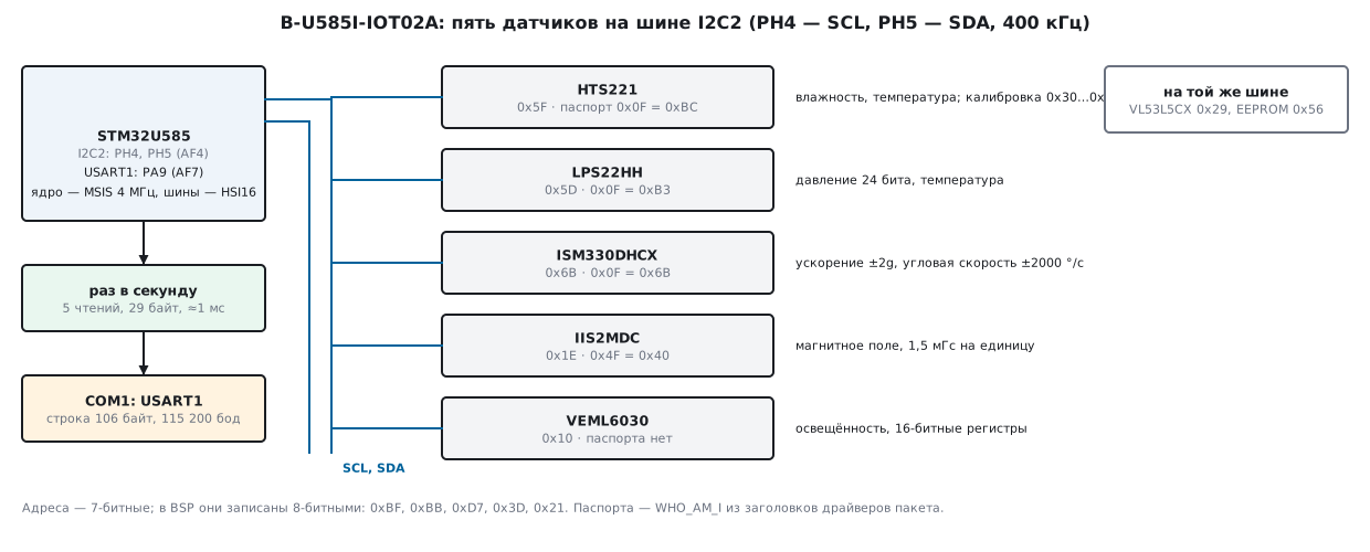
The I2C2 bus uses pins PH4 (SCL) and PH5 (SDA), alternate function 4,
open-drain with pull-up, 400 kHz (BUS_I2C2_FREQUENCY in
b_u585i_iot02a_bus.h). On the same bus the BSP keeps the VL53L5CX ranging sensor (0x29),
the M24LR64 EEPROM (0x56) and the USB power controller (TCPP03, on an expansion
board); the camera is on I2C1. Zephyr routes the data-ready outputs of the ISM330DHCX,
LPS22HH and IIS2MDC to PE11, PG2 and PD10; the BSP does not
use them, and neither do we — polling once a second works fine without interrupts.
The VEML6030 has no ID register at all: VEML6030_ReadID checks
that the address answered and returns the constant 0x6030.
198х.2 The BSP layer and our layer
The BSP splits the sensors into three groups, each with instances: ENV 0 is the
HTS221 (temperature, humidity), ENV 1 is the LPS22HH (temperature,
pressure), MOTION 0 is the ISM330DHCX (gyroscope, accelerometer), MOTION 1 is the
IIS2MDC, LIGHT 0 is the VEML6030. A call to BSP_ENV_SENSOR_Init(0, ENV_TEMPERATURE
| ENV_HUMIDITY) goes like this:
HTS221_Probefills in the bus structure — the addressHTS221_I2C_ADDRESS, the functionsBSP_I2C2_ReadReg/WriteReg,BSP_GetTick— and hands it to the component driver (HTS221_RegisterBusIO); that driver immediately callsBSP_I2C2_Init.- It reads the ID (
HTS221_ReadID) and compares it withHTS221_ID. - It stores the component's function table and calls its
Init. BSP_ENV_SENSOR_Enableturns the function on,BSP_ENV_SENSOR_GetValuereturns afloatin units: °C, %, hPa.
Convenient, but expensive: every GetValue is a separate set of transactions, and the HTS221
re-reads the calibration on every read. On the model, one read of all
five through the ST drivers takes 21 transactions and 47 bytes, of which the HTS221 takes
12 transactions and 18 bytes. Our layer is the functions i2c_rd and i2c_wr on top of
the I2C2 registers (the same exchange as in 17.10, only NBYTES = n) and one
read per sensor: 5 transactions and 29 bytes, 396 SCL clocks versus 990.
static int wait_flag(uint32_t flag)                  /* 0 — флаг есть; 1 — NACK или нет ответа */
{
    for (uint32_t n = 0; n < TMO; n++) {
        uint32_t isr = I2C2->ISR;
        if (isr & I2C_ISR_NACKF)
            return 1;
        if (isr & flag)
            return 0;
    }
    return 1;
}
int i2c_rd(uint8_t a7, uint8_t reg, uint8_t *buf, uint16_t n)   /* подадрес, повторный старт, n байт */
{
    if (n == 0u || n > 255u)
        return 1;
    I2C2->CR2 = (uint32_t)a7 << 1 | 1u << I2C_CR2_NBYTES_Pos | I2C_CR2_START;
    if (wait_flag(I2C_ISR_TXIS))
        return fail();
    I2C2->TXDR = reg;
    if (wait_flag(I2C_ISR_TC))                       /* подадрес ушёл, STOP не выдан */
        return fail();
    I2C2->CR2 = (uint32_t)a7 << 1 | I2C_CR2_RD_WRN | (uint32_t)n << I2C_CR2_NBYTES_Pos
              | I2C_CR2_AUTOEND | I2C_CR2_START;
    for (uint16_t i = 0; i < n; i++) {
        if (wait_flag(I2C_ISR_RXNE))
            return fail();
        buf[i] = (uint8_t)I2C2->RXDR;
    }
    return finish();
}
TIMINGR = 0x00500A11 was not picked by hand. Three calculation functions from
b_u585i_iot02a_bus.c (I2C_GetTiming and two helpers) were cut out without
changes and run on a PC: for a 16 MHz peripheral clock and a 400 kHz bus they give PRESC
0, SCLDEL 5, SDADEL 0, SCLH 10, SCLL 17; by the BSP formulas the period is
2529 ns, 395.4 kHz. From the 4 MHz clock after reset the algorithm also finds a
solution (0x00100003), but with SCLH = 0, so here I2C2 and USART1
are clocked from HSI16 (CCIPR1: I2C2SEL and USART1SEL = 10), while the core
stays on MSIS at 4 MHz. The BSP, by contrast, computes TIMINGR from PCLK1.
The main check of the layer is the registers. After sens_init on the model and after the
BSP chain Init + Enable for all functions, 15 configuration registers were
compared — CTRL_REG1 of the HTS221 (0x85), IF_CTRL, CTRL_REG1,
CTRL_REG2 of the LPS22HH (0x82, 0x32, 0x10), CTRL1_XL, CTRL2_G,
CTRL3_C, CTRL9_XL of the ISM330DHCX (0x40, 0x4C, 0x44, 0x02),
CFG_REG_A and CFG_REG_C of the IIS2MDC (0x0C, 0x10), ALS_CONF of the VEML6030 and
others. 15 of 15 matched. The whole configuration is 24 transactions, 900 SCL clocks,
about 2.3 ms of bus time.
198х.3 HTS221: two calibration points inside the sensor
The HTS221 returns humidity and temperature as signed 16-bit ADC samples
(0x28…0x2B). To get units, you need registers 0x30…0x3F: there
the factory has written two points of each line — a sample and a value.
The point temperatures are stored ×8 and take 10 bits: the lower 8 are in 0x32 and
0x33, the upper 2 bits of each are in 0x35; the humidities are stored ×2, in 0x30 and 0x31
(datasheet, section 8, table 19). Then comes a straight line through two points. In the
ST driver (hts221.c, BSD-3-Clause) it is written as one line:
(((y1 - y0) * Coeff) + ((x1 * y0) - (x0 * y1))) / (x1 - x0).
Our code reads the calibration once, all of it, in one transaction — this needs
bit 7 of the subaddress (0x30 | 0x80): without it the HTS221 does not increment the address
(datasheet, section 5.1.1).
static int hts_init(void)
{
    uint8_t id, cal[16];
    if (rd1(HTS_A7, 0x0F, &id) || id != 0xBC)                      /* WHO_AM_I */
        return 1;
    if (i2c_rd(HTS_A7, 0x30 | AI, cal, 16))                        /* калибровка 0x30…0x3F одним чтением */
        return 1;
    hts_cal_parse(cal, &hts_k);
    return wr1(HTS_A7, 0x20, 0x85);                                /* CTRL_REG1: PD, BDU, 1 Гц */
}
void hts_cal_parse(const uint8_t c[16], hts_cal_t *k)  /* c[0] — регистр 0x30, c[15] — 0x3F */
{
    k->h0_x2  = c[0x00];
    k->h1_x2  = c[0x01];
    k->t0_x8  = c[0x02] | (int32_t)(c[0x05] & 0x03u) << 8;         /* старшие биты T0 — 0x35[1:0] */
    k->t1_x8  = c[0x03] | (int32_t)(c[0x05] & 0x0Cu) << 6;         /* старшие биты T1 — 0x35[3:2] */
    k->h0_out = le16(&c[0x06]);                                    /* 0x36, 0x37 */
    k->h1_out = le16(&c[0x0A]);                                    /* 0x3A, 0x3B */
    k->t0_out = le16(&c[0x0C]);                                    /* 0x3C, 0x3D */
    k->t1_out = le16(&c[0x0E]);                                    /* 0x3E, 0x3F */
}
int32_t hts_temp_c100(const hts_cal_t *k, const uint8_t out[4])   /* out — 0x28…0x2B */
{
    int64_t dx = (int64_t)k->t1_out - k->t0_out;
    if (dx == 0)
        return INT32_MIN;                                          /* испорченная калибровка */
    int64_t x = le16(&out[2]) - (int64_t)k->t0_out;                /* TEMP_OUT — 0x2A, 0x2B */
    /* T = T0 + (x − x0)·(T1 − T0)/(x1 − x0); T0 и T1 хранятся ×8, ответ — ×100 */
    return (int32_t)div_round((int64_t)k->t0_x8 * 100 * dx + x * (k->t1_x8 - k->t0_x8) * 100, 8 * dx);
}
Let us work an example — the model's calibration and one sample:
| Point | Sample | Registers | Value |
|---|---|---|---|
| T0 | T0_OUT = 250 |
0x32 = 0x50, 0x35[1:0] = 0 |
80 / 8 = 10.0 °C |
| T1 | T1_OUT = 2140 |
0x33 = 0x1C, 0x35[3:2] = 1 |
284 / 8 = 35.5 °C |
| H0 | H0_T0_OUT = 1200 |
0x30 = 66 |
66 / 2 = 33.0 % |
| H1 | H1_T0_OUT = 9000 |
0x31 = 154 |
154 / 2 = 77.0 % |
Sample T_OUT = 1250: 10.0 + (1250 − 250) · 25.5 / 1890 = 23.492 °C
(0.013492 °C per count); in the line it is T=23.49. H_OUT = 3500:
33.0 + 2300 · 44 / 7800 = 45.974 %; in the line it is RH=46.0. The ST driver on the
same bytes gave 23.4921 and 45.9744 — the same thing in float. The example from the
datasheet (figures 9 and 10: samples 300 and 500 at 10 and 20 °C, 400 → 15 °C;
0x4000 and 0x6000 at 20 and 40 %, 0x5000 → 30 %) both codes reproduce
exactly: 15.00 °C and 30.0 %.
Humidity on the line can go outside 0…100 %, and the datasheet says to clip it
in software. The ST driver clips, and so does our code: a sample of 20000 gives 100.0,
a sample of −8000 gives 0. The noise is set by default by averaging, AV_CONF = 011 —
16 temperature samples and 32 humidity samples, 0.03 °C and 0.15 % (datasheet,
table 16; on what averaging gives, see section 81). Neither the BSP nor we touch this
register. CTRL_REG1 = 0x85: powered on, BDU, 1 Hz — as
after HTS221_Init and Enable.
198х.4 LPS22HH: 24-bit pressure and altitude
Pressure is three bytes PRESS_OUT_XL, _L, _H (0x28…0x2A), followed by
the temperature 0x2B, 0x2C. The conversion in the ST driver (lps22hh_reg.c):
the 24 bits are shifted left by 8 and divided by 1048576, that is, divided by
4096 — a step of 0.000244 hPa (0.0244 Pa); the temperature is divided by 100. All
of this is one read of five bytes; the sensor increments the address itself if
IF_ADD_INC (bit 4) is set in CTRL_REG2. Like the BSP, we set it explicitly.
static int lps_init(void)
{
    uint8_t id;
    if (rd1(LPS_A7, 0x0F, &id) || id != 0xB3)
        return 1;
    return set_bits(LPS_A7, 0x0E, 0, 0x82)                         /* IF_CTRL: I3C_DISABLE и INT_EN_I3C, как BSP */
        || wr1(LPS_A7, 0x11, 0x10)                                 /* CTRL_REG2: IF_ADD_INC */
        || wr1(LPS_A7, 0x10, 0x32);                                /* CTRL_REG1: 25 Гц, BDU */
}
uint32_t lps_press_pa(const uint8_t b[5])             /* b — 0x28…0x2C: давление 3 байта, температура 2 */
{
    uint32_t raw = b[0] | (uint32_t)b[1] << 8 | (uint32_t)b[2] << 16;
    return (uint32_t)((raw * 25u + 512u) / 1024u);                 /* raw/4096 гПа = raw·100/4096 Па */
}
int32_t alt_dm(uint32_t p_pa, uint32_t p0_pa)         /* барометрическая формула из раздела 98 */
{
    float h = 44330.0f * (1.0f - powf((float)p_pa / (float)p0_pa, 1.0f / 5.255f));
    return (int32_t)lroundf(h * 10.0f);
}
The model's scene: the bytes 0x00, 0xE0, 0x3D — 0x3DE000 = 4055040,
divided by 4096, gives 990.00 hPa, in the line P=990.00; the temperature
2410 gives TP=24.10. The altitude by the formula of section 98 from 1013.25 hPa is
195.4 m (Python gives 195.391 m), for 1012.00 hPa it is 10.4 m. This is the altitude
relative to the chosen p0; how the weather shifts it by hundreds of meters is
covered in section 98.
A finding in the ST driver. LPS22HH_Init turns on low-noise mode: after
it, CTRL_REG2 = 0x12 (LOW_NOISE_EN and IF_ADD_INC). But
LPS22HH_TEMP_Enable writes the 25 Hz rate (LPS22HH_25_Hz = 0x03), and
together with it the low-noise bit taken from the same number, that is, 0. After Enable
the register holds 0x10: low-noise mode is gone. Our code reproduces the BSP result (0x10)
so that the register comparison is fair; if you need low noise, write
CTRL_REG2 after choosing the rate. Also, IF_CTRL = 0x82, not 0x02:
the value LPS22HH_I3C_DISABLE = 0x11 also sets INT_EN_I3C — we
write the same.
198х.5 ISM330DHCX and IIS2MDC: the range decides everything
The ISM330DHCX returns six axes in a row: gyroscope 0x22…0x27, accelerometer
0x28…0x2D — 12 bytes in one read with IF_INC set in CTRL3_C.
The sensitivity is in ism330dhcx.h:
| Accelerometer | mg per count | Gyroscope | mdps per count |
|---|---|---|---|
| ±2g | 0.061 | ±125 °/s | 4.375 |
| ±4g | 0.122 | ±250 °/s | 8.75 |
| ±8g | 0.244 | ±500 °/s | 17.5 |
| ±16g | 0.488 | ±1000 °/s | 35 |
| ±2000 °/s | 70 | ||
| ±4000 °/s | 140 |
The BSP sets ±2g and ±2000 °/s, a rate of 104 Hz (CTRL1_XL = 0x40,
CTRL2_G = 0x4C). At ±2g, 1 g is 16393 counts. The codes of the FS_XL field
are not in order: 00 is ±2g, 01 is ±16g, 10 is ±4g, 11 is ±8g
(the enumeration ism330dhcx_fs_xl_t). The gyroscope has four bits: FS_4000,
FS_125 and the two bits of FS_G.
static int ism_init(void)
{
    uint8_t id, v = 1;
    if (rd1(ISM_A7, 0x0F, &id) || id != 0x6B)
        return 1;
    if (wr1(ISM_A7, 0x12, 0x01))                                   /* CTRL3_C: SW_RESET */
        return 1;
    for (int n = 0; n < 1000 && (v & 1u); n++)                     /* бит снимается сам */
        if (rd1(ISM_A7, 0x12, &v))
            return 1;
    return (v & 1u)
        || wr1(ISM_A7, 0x12, 0x44)                                 /* CTRL3_C: BDU, IF_INC */
        || set_bits(ISM_A7, 0x18, 0, 0x02)                         /* CTRL9_XL: DEVICE_CONF */
        || set_bits(ISM_A7, 0x0A, 0x07, 0)                         /* FIFO_CTRL4: FIFO выключен */
        || wr1(ISM_A7, 0x10, 0x40 | ISM_FS_XL << 2)                /* CTRL1_XL: 104 Гц, ±2g */
        || wr1(ISM_A7, 0x11, 0x40 | ISM_FS_G);                     /* CTRL2_G: 104 Гц, ±2000 °/с */
}
int32_t ism_acc_mg(int16_t raw, uint8_t fs_xl)        /* FS_XL: 00 ±2g, 01 ±16g, 10 ±4g, 11 ±8g */
{
    static const int32_t ug_per_lsb[4] = {61, 488, 122, 244};
    return (int32_t)div_round((int64_t)raw * ug_per_lsb[fs_xl & 3u], 1000);
}
int32_t ism_gyr_mdps(int16_t raw, uint8_t fs_g)       /* 4 бита CTRL2_G[3:0]: FS_G[1:0], FS_125, FS_4000 */
{
    int32_t udps;                                                  /* микроградусы в секунду на единицу */
    if (fs_g & 1u)       udps = 140000;                            /* ±4000 */
    else if (fs_g & 2u)  udps = 4375;                              /* ±125 */
    else                 udps = 8750 << (fs_g >> 2);               /* ±250, 500, 1000, 2000 */
    return (int32_t)div_round((int64_t)raw * udps, 1000);
}
The ST driver multiplies the sample by a float and casts to int32_t — the fraction
is truncated toward zero. We round:
| Sample | Exact, mg | Our code | ST driver |
|---|---|---|---|
| 328 | 20.008 | 20 | 20 |
| −205 | −12.505 | −13 | −12 |
| 16393 | 999.973 | 1000 | 999 |
The difference is at most one count, but "999 mg" on a table lying perfectly level is
confusing. The gyroscope at ±2000 °/s is exactly 70 mdps per count: a sample of 16
gives 1120 mdps (G=1.12), −3 gives −210.
The IIS2MDC has a single range — 50 gauss, 1.5 mG per count
(IIS2MDC_MAG_SENSITIVITY_FS_50GAUSS), six bytes from 0x68. The BSP turns on
BDU in CFG_REG_C (0x10) and continuous mode at 100 Hz in CFG_REG_A
(0x0C). A sample of −101: exactly −151.5, ours gives −152, ST gives −151.
198х.6 VEML6030: lux from gain and time, a line to the UART
The VEML6030 is not an ST sensor and is built differently: its registers are 16-bit, each has
a command code (0x00 — ALS_CONF, 0x04 — ALS, 0x05 — WHITE), two
bytes per register. The package driver does not compute lux at all:
VEML6030_GetValues returns the count. The coefficient is in the Zephyr driver
veml7700 — the same driver Zephyr assigns to the VEML6030 on this board: a 4 × 6 table,
from 0.0036 lx per count (gain ×2, 800 ms) to 1.8432 (×1/8, 25 ms).
The whole table folds into one formula — 0.0036 · (800 / time) ·
(2 / gain); the run checked all 24 numbers.
uint32_t veml_res_ulx(uint8_t gain, uint8_t it)       /* микролюксы на единицу счёта */
{
    static const uint8_t gmul[4] = {2, 1, 16, 8};                  /* ALS_GAIN: 00 ×1, 01 ×2, 10 ×1/8, 11 ×1/4 */
    uint32_t tmul;
    switch (it) {                                                  /* ALS_IT, мс: 25, 50, 100, 200, 400, 800 */
    case 0x0C: tmul = 32; break;
    case 0x08: tmul = 16; break;
    case 0x00: tmul = 8;  break;
    case 0x01: tmul = 4;  break;
    case 0x02: tmul = 2;  break;
    case 0x03: tmul = 1;  break;
    default:   return 0;
    }
    return 3600u * gmul[gain & 3u] * tmul;                         /* 0,0036 лк при ×2 и 800 мс */
}
The BSP leaves the gain at ×1 and 100 ms (BSP_LIGHT_SENSOR_Init writes them
only into its own structure, not into the sensor; our veml_init writes them explicitly): 0.0576 lx per
count, a count of 6000 gives 345.6 lx (L=345.6), the ceiling of 65535 gives 3774.8 lx.
For bright sunlight use gain ×1/8 and 25 ms: the ceiling is 120794 lx.
The combined poll is five reads in a row, one per sensor:
void sens_poll(uint8_t mask, sens_t *v)
{
    uint8_t b[12];
    v->ok = 0;
    if ((mask & 1u) && !i2c_rd(HTS_A7, 0x28 | AI, b, 4)) {        /* HUMIDITY_OUT, TEMP_OUT */
        v->rh_x10 = hts_rh_x10(&hts_k, b);
        v->t_c100 = hts_temp_c100(&hts_k, b);
        v->ok |= 1u;
    }
    if ((mask & 2u) && !i2c_rd(LPS_A7, 0x28, b, 5)) {             /* PRESS_OUT_XL…TEMP_OUT_H */
        v->p_pa = lps_press_pa(b);
        v->tp_c100 = lps_temp_c100(b);
        v->alt_dm = alt_dm(v->p_pa, P0_PA);
        v->ok |= 2u;
    }
    if ((mask & 4u) && !i2c_rd(ISM_A7, 0x22, b, 12)) {            /* OUTX_L_G…OUTZ_H_A */
        for (int i = 0; i < 3; i++) {
            v->gyr_mdps[i] = ism_gyr_mdps(le16(&b[2 * i]), ISM_FS_G);
            v->acc_mg[i] = ism_acc_mg(le16(&b[6 + 2 * i]), ISM_FS_XL);
        }
        v->ok |= 4u;
    }
    if ((mask & 8u) && !i2c_rd(MAG_A7, 0x68 | AI, b, 6)) {        /* OUTX_L_REG…OUTZ_H_REG */
        for (int i = 0; i < 3; i++)
            v->mag_mg[i] = mag_mg(le16(&b[2 * i]));
        v->ok |= 8u;
    }
    if ((mask & 16u) && !i2c_rd(VEML_A7, 0x04, b, 2)) {           /* ALS */
        v->lux_mlx = veml_mlx((uint16_t)le16(b), VEML_GAIN, VEML_IT);
        v->ok |= 16u;
    }
}
int main(void)
{
    static sens_t v;
    static char line[160];
    board_init();
    uint8_t mask = sens_init();
    uint32_t next = ms + 1000u;
    for (;;) {
        if ((int32_t)(ms - next) < 0) {
            __WFI();                                 /* SysTick будит раз в миллисекунду */
            continue;
        }
        next += 1000u;
        sens_poll(mask, &v);
        uart_send(line, fmt_line(line, &v));
    }
}
The model's line is 106 bytes including \r\n:
S=1F T=23.49 RH=46.0 P=990.00 TP=24.10 ALT=195.4 A=20,-13,1000 G=1.12,-0.21,0.00 M=300,-152,-600 L=345.6
S=1F means all five answered. At 115200 baud (BRR = 139 from 16 MHz,
115108 baud, −0.08 %) the line goes out in 9.2 ms; the bus for the whole poll is
396 SCL clocks, about 1.0 ms. armclang 6.24 built the firmware without
warnings: the code of sens_u585.c is 840 bytes, sens_dev.c is 946,
sens_conv.c is 1348 (3134 bytes in total), RAM is 256 bytes.
_Static_assert statements hold BRR = 139 and the TIMINGR fields: a copy with 9600 baud does not
build.
198х.7 Pitfalls
An 8-bit address instead of a 7-bit one. The BSP stores addresses shifted and with the read bit:
the HTS221 is 0xBF, while on the bus it is 0x5F. Pass 0xBF to a function that
shifts the address itself (like our i2c_rd), and the SADD field gets 0x17E, while the peripheral
in 7-bit mode looks only at SADD[7:1] (RM0456, register I2C_CR2) —
0x3F goes out on the bus. On the
model, all five 8-bit BSP addresses passed as 7-bit ones give 0 answers
out of 5. The opposite mistake is 0x5F in HAL_I2C_Mem_Read, which expects an already
shifted address: 0x2F goes out on the bus.
A burst read without auto-increment. The HTS221 increments the address only when
bit 7 of the subaddress is set. Without it, four bytes from 0x28 are four copies of one
register (0xAC), and the model shows −281.19 °C. The calibration without bit 7 is
16 copies of 0x30: T0_OUT = T1_OUT, the line's divisor is zero (our code
returns INT32_MIN and does not divide). The LPS22HH and ISM330DHCX have a different rule
— a bit in a control register; the LPS22HH with IF_ADD_INC cleared returns on the model
five identical bytes — 0.00 hPa.
Byte order. ST sensors send the low byte first. Assemble the high byte
first, and a sample of 16393 (bytes 0x09, 0x40) turns into 2368, and 1 g
reads as 144 mg. The IIS2MDC has a BLE bit in CFG_REG_C: 0 means the low
byte at the lower address, 1 means the high byte (iis2mdc_ble_t); keep it at zero.
VEML6030: the drivers disagree about byte order. Zephyr assembles the register
low byte first (sys_get_le16), while the ST driver swaps the bytes after reading
(veml6030_read_reg). On the model with the low byte first, the ST driver
reads 6000 as 0x7017 = 28695 (1652.8 lx); if ST is right, then our code is wrong
in exactly the same way. This has not been checked against the Vishay datasheet; the
board will decide.
Half of a uint32_t. VEML6030_GetValues writes 16 bits through
(uint16_t *) into a uint32_t array — the upper half stays as it
was. An array filled with 0xDEADBEEF is 0xDEAD7017 after the call.
Zero the array before the call.
Code 01 in FS_XL is ±16g. Anyone who expects ±4g by order will get 1 g as
2049 counts and, multiplying by 0.122, 250 mg.
Calibration — once. The ST driver re-reads it on every measurement: 12 transactions for one HTS221 read instead of one.
The LPS22HH low-noise mode is lost in Enable. See 198х.4: after
LPS22HH_Init the bit is set, after Enable with 25 Hz it is cleared.
198х.8 Summary
- Five sensors on I2C2 (
PH4,PH5): HTS221 0x5F, LPS22HH 0x5D, ISM330DHCX 0x6B, IIS2MDC 0x1E, VEML6030 0x10; IDs0xBC,0xB3,0x6B,0x40, the VEML6030 has no ID. - HTS221: a straight line through two factory points; the example gives 23.492 °C and 45.974 %, the ST driver matched, the datasheet example gives exactly 15.00 °C and 30.0 %.
- LPS22HH: 24 bits / 4096 = hPa, 0x3DE000 is 990.00 hPa, 195.4 m from
1013.25 hPa; the low-noise mode from
LPS22HH_Initis cleared byEnable. - ISM330DHCX: 0.061 mg and 70 mdps per count at ±2g and ±2000 °/s; ST
truncates the fraction (999 mg instead of 1000); the
FS_XLcode 01 is ±16g. - VEML6030: 0.0036 · (800 / time) · (2 / gain) lx — all 24 numbers of the Zephyr table; ×1 and 100 ms give 0.0576 lx, 6000 gives 345.6 lx.
- Polling: 5 transactions, 29 bytes, about 1.0 ms of bus time at 395.4 kHz versus 21 transactions and 47 bytes through the BSP; configuration — 15 registers of 15 as in the BSP.
- A 106-byte line once a second, 9.2 ms at 115200 baud; the firmware is 3134 bytes of code, 256 bytes of RAM.
Full sources
sens_dev.c — configuring and polling the B-U585I-IOT02A sensors.
/* sens_dev.c — раздел 198х: настройка и опрос датчиков B-U585I-IOT02A.
   Регистры и значения — как у драйверов компонентов пакета B-U585I-IOT02A_BSP (BSD-3-Clause):
   после sens_init регистры настройки совпадают с тем, что оставляют BSP_*_Init + BSP_*_Enable. */
#include "sens_dev.h"

#define AI 0x80u                 /* бит 7 подадреса: автоинкремент у HTS221 (и так же делает BSP для IIS2MDC) */
#define ISM_FS_XL   0u           /* ±2g */
#define ISM_FS_G    12u          /* ±2000 °/с */
#define VEML_GAIN   0u           /* ×1 */
#define VEML_IT     0u           /* 100 мс */

static hts_cal_t hts_k;

static int wr1(uint8_t a7, uint8_t reg, uint8_t v)
{
    return i2c_wr(a7, reg, &v, 1);
}

static int rd1(uint8_t a7, uint8_t reg, uint8_t *v)
{
    return i2c_rd(a7, reg, v, 1);
}

static int set_bits(uint8_t a7, uint8_t reg, uint8_t clr, uint8_t set)   /* чтение-правка-запись */
{
    uint8_t v;
    if (rd1(a7, reg, &v))
        return 1;
    return wr1(a7, reg, (uint8_t)((v & ~clr) | set));
}

static int hts_init(void)
{
    uint8_t id, cal[16];
    if (rd1(HTS_A7, 0x0F, &id) || id != 0xBC)                      /* WHO_AM_I */
        return 1;
    if (i2c_rd(HTS_A7, 0x30 | AI, cal, 16))                        /* калибровка 0x30…0x3F одним чтением */
        return 1;
    hts_cal_parse(cal, &hts_k);
    return wr1(HTS_A7, 0x20, 0x85);                                /* CTRL_REG1: PD, BDU, 1 Гц */
}

static int lps_init(void)
{
    uint8_t id;
    if (rd1(LPS_A7, 0x0F, &id) || id != 0xB3)
        return 1;
    return set_bits(LPS_A7, 0x0E, 0, 0x82)                         /* IF_CTRL: I3C_DISABLE и INT_EN_I3C, как BSP */
        || wr1(LPS_A7, 0x11, 0x10)                                 /* CTRL_REG2: IF_ADD_INC */
        || wr1(LPS_A7, 0x10, 0x32);                                /* CTRL_REG1: 25 Гц, BDU */
}

static int ism_init(void)
{
    uint8_t id, v = 1;
    if (rd1(ISM_A7, 0x0F, &id) || id != 0x6B)
        return 1;
    if (wr1(ISM_A7, 0x12, 0x01))                                   /* CTRL3_C: SW_RESET */
        return 1;
    for (int n = 0; n < 1000 && (v & 1u); n++)                     /* бит снимается сам */
        if (rd1(ISM_A7, 0x12, &v))
            return 1;
    return (v & 1u)
        || wr1(ISM_A7, 0x12, 0x44)                                 /* CTRL3_C: BDU, IF_INC */
        || set_bits(ISM_A7, 0x18, 0, 0x02)                         /* CTRL9_XL: DEVICE_CONF */
        || set_bits(ISM_A7, 0x0A, 0x07, 0)                         /* FIFO_CTRL4: FIFO выключен */
        || wr1(ISM_A7, 0x10, 0x40 | ISM_FS_XL << 2)                /* CTRL1_XL: 104 Гц, ±2g */
        || wr1(ISM_A7, 0x11, 0x40 | ISM_FS_G);                     /* CTRL2_G: 104 Гц, ±2000 °/с */
}

static int mag_init(void)
{
    uint8_t id;
    if (rd1(MAG_A7, 0x4F | AI, &id) || id != 0x40)
        return 1;
    return set_bits(MAG_A7, 0x62 | AI, 0x02, 0x10)                 /* CFG_REG_C: BDU, без самотеста */
        || wr1(MAG_A7, 0x60 | AI, 0x0C);                           /* CFG_REG_A: 100 Гц, непрерывно */
}

static int veml_init(void)
{
    uint8_t conf[2];
    if (i2c_rd(VEML_A7, 0x00, conf, 2))                            /* паспорта нет: хватит ответа на адрес */
        return 1;
    conf[0] = (uint8_t)(VEML_GAIN << 11 | VEML_IT << 6);           /* ALS_CONF, младший байт первым; SD = 0 */
    conf[1] = (uint8_t)((VEML_GAIN << 11 | VEML_IT << 6) >> 8);
    return i2c_wr(VEML_A7, 0x00, conf, 2);
}

uint8_t sens_init(void)
{
    uint8_t m = 0;
    m |= (uint8_t)(!hts_init()  << 0);
    m |= (uint8_t)(!lps_init()  << 1);
    m |= (uint8_t)(!ism_init()  << 2);
    m |= (uint8_t)(!mag_init()  << 3);
    m |= (uint8_t)(!veml_init() << 4);
    return m;
}

void sens_poll(uint8_t mask, sens_t *v)
{
    uint8_t b[12];
    v->ok = 0;
    if ((mask & 1u) && !i2c_rd(HTS_A7, 0x28 | AI, b, 4)) {        /* HUMIDITY_OUT, TEMP_OUT */
        v->rh_x10 = hts_rh_x10(&hts_k, b);
        v->t_c100 = hts_temp_c100(&hts_k, b);
        v->ok |= 1u;
    }
    if ((mask & 2u) && !i2c_rd(LPS_A7, 0x28, b, 5)) {             /* PRESS_OUT_XL…TEMP_OUT_H */
        v->p_pa = lps_press_pa(b);
        v->tp_c100 = lps_temp_c100(b);
        v->alt_dm = alt_dm(v->p_pa, P0_PA);
        v->ok |= 2u;
    }
    if ((mask & 4u) && !i2c_rd(ISM_A7, 0x22, b, 12)) {            /* OUTX_L_G…OUTZ_H_A */
        for (int i = 0; i < 3; i++) {
            v->gyr_mdps[i] = ism_gyr_mdps(le16(&b[2 * i]), ISM_FS_G);
            v->acc_mg[i] = ism_acc_mg(le16(&b[6 + 2 * i]), ISM_FS_XL);
        }
        v->ok |= 4u;
    }
    if ((mask & 8u) && !i2c_rd(MAG_A7, 0x68 | AI, b, 6)) {        /* OUTX_L_REG…OUTZ_H_REG */
        for (int i = 0; i < 3; i++)
            v->mag_mg[i] = mag_mg(le16(&b[2 * i]));
        v->ok |= 8u;
    }
    if ((mask & 16u) && !i2c_rd(VEML_A7, 0x04, b, 2)) {           /* ALS */
        v->lux_mlx = veml_mlx((uint16_t)le16(b), VEML_GAIN, VEML_IT);
        v->ok |= 16u;
    }
}
sens_conv.c — raw sensor bytes → units, in integers.
/* sens_conv.c — раздел 198х: сырые байты датчиков → единицы, целыми числами.
   Формулы и коэффициенты — из драйверов компонентов пакета B-U585I-IOT02A_BSP (BSD-3-Clause),
   коэффициенты VEML6030 — из драйвера veml7700 проекта Zephyr (Apache-2.0). */
#include <math.h>
#include "sens_conv.h"

static int64_t div_round(int64_t a, int64_t b)       /* деление с округлением к ближайшему, b > 0 */
{
    return (a >= 0 ? a + b / 2 : a - b / 2) / b;
}

int16_t le16(const uint8_t *p)                        /* младший байт первым */
{
    return (int16_t)(uint16_t)(p[0] | (uint16_t)p[1] << 8);
}

void hts_cal_parse(const uint8_t c[16], hts_cal_t *k)  /* c[0] — регистр 0x30, c[15] — 0x3F */
{
    k->h0_x2  = c[0x00];
    k->h1_x2  = c[0x01];
    k->t0_x8  = c[0x02] | (int32_t)(c[0x05] & 0x03u) << 8;         /* старшие биты T0 — 0x35[1:0] */
    k->t1_x8  = c[0x03] | (int32_t)(c[0x05] & 0x0Cu) << 6;         /* старшие биты T1 — 0x35[3:2] */
    k->h0_out = le16(&c[0x06]);                                    /* 0x36, 0x37 */
    k->h1_out = le16(&c[0x0A]);                                    /* 0x3A, 0x3B */
    k->t0_out = le16(&c[0x0C]);                                    /* 0x3C, 0x3D */
    k->t1_out = le16(&c[0x0E]);                                    /* 0x3E, 0x3F */
}

int32_t hts_temp_c100(const hts_cal_t *k, const uint8_t out[4])   /* out — 0x28…0x2B */
{
    int64_t dx = (int64_t)k->t1_out - k->t0_out;
    if (dx == 0)
        return INT32_MIN;                                          /* испорченная калибровка */
    int64_t x = le16(&out[2]) - (int64_t)k->t0_out;                /* TEMP_OUT — 0x2A, 0x2B */
    /* T = T0 + (x − x0)·(T1 − T0)/(x1 − x0); T0 и T1 хранятся ×8, ответ — ×100 */
    return (int32_t)div_round((int64_t)k->t0_x8 * 100 * dx + x * (k->t1_x8 - k->t0_x8) * 100, 8 * dx);
}

int32_t hts_rh_x10(const hts_cal_t *k, const uint8_t out[4])
{
    int64_t dx = (int64_t)k->h1_out - k->h0_out;
    if (dx == 0)
        return INT32_MIN;
    int64_t x = le16(&out[0]) - (int64_t)k->h0_out;                /* HUMIDITY_OUT — 0x28, 0x29 */
    int64_t rh = div_round((int64_t)k->h0_x2 * 10 * dx + x * (k->h1_x2 - k->h0_x2) * 10, 2 * dx);
    return (int32_t)(rh < 0 ? 0 : rh > 1000 ? 1000 : rh);          /* как драйвер ST: 0…100 % */
}

uint32_t lps_press_pa(const uint8_t b[5])             /* b — 0x28…0x2C: давление 3 байта, температура 2 */
{
    uint32_t raw = b[0] | (uint32_t)b[1] << 8 | (uint32_t)b[2] << 16;
    return (uint32_t)((raw * 25u + 512u) / 1024u);                 /* raw/4096 гПа = raw·100/4096 Па */
}

int32_t lps_temp_c100(const uint8_t b[5])
{
    return le16(&b[3]);                                            /* уже в сотых °C */
}

int32_t alt_dm(uint32_t p_pa, uint32_t p0_pa)         /* барометрическая формула из раздела 98 */
{
    float h = 44330.0f * (1.0f - powf((float)p_pa / (float)p0_pa, 1.0f / 5.255f));
    return (int32_t)lroundf(h * 10.0f);
}

int32_t ism_acc_mg(int16_t raw, uint8_t fs_xl)        /* FS_XL: 00 ±2g, 01 ±16g, 10 ±4g, 11 ±8g */
{
    static const int32_t ug_per_lsb[4] = {61, 488, 122, 244};
    return (int32_t)div_round((int64_t)raw * ug_per_lsb[fs_xl & 3u], 1000);
}

int32_t ism_gyr_mdps(int16_t raw, uint8_t fs_g)       /* 4 бита CTRL2_G[3:0]: FS_G[1:0], FS_125, FS_4000 */
{
    int32_t udps;                                                  /* микроградусы в секунду на единицу */
    if (fs_g & 1u)       udps = 140000;                            /* ±4000 */
    else if (fs_g & 2u)  udps = 4375;                              /* ±125 */
    else                 udps = 8750 << (fs_g >> 2);               /* ±250, 500, 1000, 2000 */
    return (int32_t)div_round((int64_t)raw * udps, 1000);
}

int32_t mag_mg(int16_t raw)                           /* 1,5 мГс на единицу */
{
    return (int32_t)div_round((int64_t)raw * 3, 2);
}

uint32_t veml_res_ulx(uint8_t gain, uint8_t it)       /* микролюксы на единицу счёта */
{
    static const uint8_t gmul[4] = {2, 1, 16, 8};                  /* ALS_GAIN: 00 ×1, 01 ×2, 10 ×1/8, 11 ×1/4 */
    uint32_t tmul;
    switch (it) {                                                  /* ALS_IT, мс: 25, 50, 100, 200, 400, 800 */
    case 0x0C: tmul = 32; break;
    case 0x08: tmul = 16; break;
    case 0x00: tmul = 8;  break;
    case 0x01: tmul = 4;  break;
    case 0x02: tmul = 2;  break;
    case 0x03: tmul = 1;  break;
    default:   return 0;
    }
    return 3600u * gmul[gain & 3u] * tmul;                         /* 0,0036 лк при ×2 и 800 мс */
}

uint32_t veml_mlx(uint16_t counts, uint8_t gain, uint8_t it)
{
    return (uint32_t)(((uint64_t)counts * veml_res_ulx(gain, it) + 500u) / 1000u);
}

/* ── строка в UART ──────────────────────────────────────────────────────── */
static char *put_u(char *p, uint32_t v)
{
    char t[10];
    int n = 0;
    do {
        t[n++] = (char)('0' + v % 10u);
        v /= 10u;
    } while (v);
    while (n)
        *p++ = t[--n];
    return p;
}

static char *put_fix(char *p, int32_t v, unsigned dec)  /* v в единицах 10^-dec */
{
    uint32_t a = v < 0 ? 0u - (uint32_t)v : (uint32_t)v, d = 1;
    for (unsigned i = 0; i < dec; i++)
        d *= 10u;
    if (v < 0)
        *p++ = '-';
    p = put_u(p, a / d);
    if (dec) {
        uint32_t f = a % d;
        *p++ = '.';
        for (uint32_t q = d / 10u; q; q /= 10u) {
            *p++ = (char)('0' + f / q);
            f %= q;
        }
    }
    return p;
}

static char *put_s(char *p, const char *s)
{
    while (*s)
        *p++ = *s++;
    return p;
}

static char *put_xyz(char *p, const char *name, const int32_t v[3], unsigned dec)
{
    p = put_s(p, name);
    for (int i = 0; i < 3; i++) {
        if (i)
            *p++ = ',';
        p = put_fix(p, v[i], dec);
    }
    return p;
}

int fmt_line(char *s, const sens_t *v)                /* нужно до 160 байт */
{
    static const char hex[] = "0123456789ABCDEF";
    int32_t g[3];
    char *p = put_s(s, "S=");
    *p++ = hex[v->ok >> 4 & 0xFu];
    *p++ = hex[v->ok & 0xFu];
    p = put_s(p, " T=");   p = put_fix(p, v->t_c100, 2);
    p = put_s(p, " RH=");  p = put_fix(p, v->rh_x10, 1);
    p = put_s(p, " P=");   p = put_fix(p, (int32_t)v->p_pa, 2);
    p = put_s(p, " TP=");  p = put_fix(p, v->tp_c100, 2);
    p = put_s(p, " ALT="); p = put_fix(p, v->alt_dm, 1);
    p = put_xyz(p, " A=", v->acc_mg, 0);
    for (int i = 0; i < 3; i++)
        g[i] = (int32_t)div_round(v->gyr_mdps[i], 10);             /* сотые °/с */
    p = put_xyz(p, " G=", g, 2);
    p = put_xyz(p, " M=", v->mag_mg, 0);
    p = put_s(p, " L=");   p = put_fix(p, (int32_t)((v->lux_mlx + 50u) / 100u), 1);
    p = put_s(p, "\r\n");
    *p = 0;
    return (int)(p - s);
}
sens_u585.c — the sensor polling firmware, on registers, without HAL.
/* sens_u585.c — раздел 198х: прошивка опроса датчиков B-U585I-IOT02A, регистрами, без HAL.
   Ядро на MSIS 4 МГц после сброса; I2C2 и USART1 тактуются от HSI16. Раз в секунду — строка в USART1.
   Выводы — как в BSP платы: I2C2 — PH4 (SCL) и PH5 (SDA), AF4; COM1 — USART1, PA9 (TX), AF7. */
#include "stm32u585xx.h"
#include "sens_dev.h"

#define HSI_HZ    16000000u
#define BAUD      115200u
#define UART_BRR  ((HSI_HZ + BAUD / 2u) / BAUD)
#define I2C_TIMING 0x00500A11u    /* 400 кГц от 16 МГц — алгоритм I2C_GetTiming из BSP (timing198h.py) */
#define TMO       100000u         /* предел ожидания флага, итераций */

_Static_assert(UART_BRR == 139u, "USART1: 16 МГц / 115200");
_Static_assert((I2C_TIMING >> 28) == 0u && (I2C_TIMING & 0xFFu) == 17u && ((I2C_TIMING >> 8) & 0xFFu) == 10u, "поля TIMINGR");

static volatile uint32_t ms;

void SysTick_Handler(void)
{
    ms++;
}

static void board_init(void)
{
    RCC->CR |= RCC_CR_HSION;
    while (!(RCC->CR & RCC_CR_HSIRDY)) {
    }
    RCC->CCIPR1 = (RCC->CCIPR1 & ~(RCC_CCIPR1_USART1SEL | RCC_CCIPR1_I2C2SEL))
                | 2u << RCC_CCIPR1_USART1SEL_Pos | 2u << RCC_CCIPR1_I2C2SEL_Pos;       /* 10 — HSI16 */
    RCC->AHB2ENR1 |= RCC_AHB2ENR1_GPIOAEN | RCC_AHB2ENR1_GPIOHEN;
    RCC->APB1ENR1 |= RCC_APB1ENR1_I2C2EN;
    RCC->APB2ENR |= RCC_APB2ENR_USART1EN;
    (void)RCC->APB2ENR;

    /* PH4, PH5: альтернативная функция 4, открытый сток, подтяжка вверх, высокая скорость — как BSP */
    GPIOH->AFR[0] = (GPIOH->AFR[0] & ~(0xFFu << 16)) | 4u << 16 | 4u << 20;
    GPIOH->OTYPER |= 3u << 4;
    GPIOH->OSPEEDR = (GPIOH->OSPEEDR & ~(0xFu << 8)) | 0xAu << 8;
    GPIOH->PUPDR = (GPIOH->PUPDR & ~(0xFu << 8)) | 0x5u << 8;
    GPIOH->MODER = (GPIOH->MODER & ~(0xFu << 8)) | 0xAu << 8;
    /* PA9: USART1_TX, альтернативная функция 7 */
    GPIOA->AFR[1] = (GPIOA->AFR[1] & ~(0xFu << 4)) | 7u << 4;
    GPIOA->MODER = (GPIOA->MODER & ~(3u << 18)) | 2u << 18;

    I2C2->CR1 = 0;                                   /* PE = 0: TIMINGR меняется только выключенным */
    I2C2->TIMINGR = I2C_TIMING;
    I2C2->CR1 = I2C_CR1_PE;                          /* аналоговый фильтр включён (ANFOFF = 0) */

    USART1->BRR = UART_BRR;
    USART1->CR1 = USART_CR1_TE | USART_CR1_UE;

    SysTick->LOAD = 4000u - 1u;                      /* 1 мс при MSIS 4 МГц */
    SysTick->VAL = 0;
    SysTick->CTRL = SysTick_CTRL_CLKSOURCE_Msk | SysTick_CTRL_TICKINT_Msk | SysTick_CTRL_ENABLE_Msk;
}

static int wait_flag(uint32_t flag)                  /* 0 — флаг есть; 1 — NACK или нет ответа */
{
    for (uint32_t n = 0; n < TMO; n++) {
        uint32_t isr = I2C2->ISR;
        if (isr & I2C_ISR_NACKF)
            return 1;
        if (isr & flag)
            return 0;
    }
    return 1;
}

static int fail(void)                                /* после NACK блок сам выдаёт STOP; иначе — просим */
{
    if (!(I2C2->ISR & I2C_ISR_NACKF))
        I2C2->CR2 |= I2C_CR2_STOP;
    for (uint32_t n = 0; n < TMO && !(I2C2->ISR & I2C_ISR_STOPF); n++) {
    }
    I2C2->ICR = I2C_ICR_NACKCF | I2C_ICR_STOPCF;
    return 1;
}

static int finish(void)
{
    if (wait_flag(I2C_ISR_STOPF))
        return fail();
    I2C2->ICR = I2C_ICR_STOPCF;                      /* пока STOPF стоит, блок занят */
    return 0;
}

int i2c_rd(uint8_t a7, uint8_t reg, uint8_t *buf, uint16_t n)   /* подадрес, повторный старт, n байт */
{
    if (n == 0u || n > 255u)
        return 1;
    I2C2->CR2 = (uint32_t)a7 << 1 | 1u << I2C_CR2_NBYTES_Pos | I2C_CR2_START;
    if (wait_flag(I2C_ISR_TXIS))
        return fail();
    I2C2->TXDR = reg;
    if (wait_flag(I2C_ISR_TC))                       /* подадрес ушёл, STOP не выдан */
        return fail();
    I2C2->CR2 = (uint32_t)a7 << 1 | I2C_CR2_RD_WRN | (uint32_t)n << I2C_CR2_NBYTES_Pos
              | I2C_CR2_AUTOEND | I2C_CR2_START;
    for (uint16_t i = 0; i < n; i++) {
        if (wait_flag(I2C_ISR_RXNE))
            return fail();
        buf[i] = (uint8_t)I2C2->RXDR;
    }
    return finish();
}

int i2c_wr(uint8_t a7, uint8_t reg, const uint8_t *buf, uint16_t n)  /* подадрес и n байт одной посылкой */
{
    if (n > 254u)
        return 1;
    I2C2->CR2 = (uint32_t)a7 << 1 | (uint32_t)(n + 1u) << I2C_CR2_NBYTES_Pos | I2C_CR2_AUTOEND | I2C_CR2_START;
    for (uint16_t i = 0; i <= n; i++) {
        if (wait_flag(I2C_ISR_TXIS))
            return fail();
        I2C2->TXDR = i ? buf[i - 1u] : reg;
    }
    return finish();
}

static void uart_send(const char *s, int n)
{
    for (int i = 0; i < n; i++) {
        while (!(USART1->ISR & USART_ISR_TXE_TXFNF)) {
        }
        USART1->TDR = (uint8_t)s[i];
    }
}

int main(void)
{
    static sens_t v;
    static char line[160];
    board_init();
    uint8_t mask = sens_init();
    uint32_t next = ms + 1000u;
    for (;;) {
        if ((int32_t)(ms - next) < 0) {
            __WFI();                                 /* SysTick будит раз в миллисекунду */
            continue;
        }
        next += 1000u;
        sens_poll(mask, &v);
        uart_send(line, fmt_line(line, &v));
    }
}
Next: section 198ц "Mini-project: a log in the external Octo-SPI flash of the B-U585I-IOT02A" — the lines of this poll go into the MX25LM51245G on OCTOSPI2 and survive power-off.