 Embedded HandbookApps
198ц. Mini-project: a log in the external Octo-SPI flash of the B-U585I-IOT02A
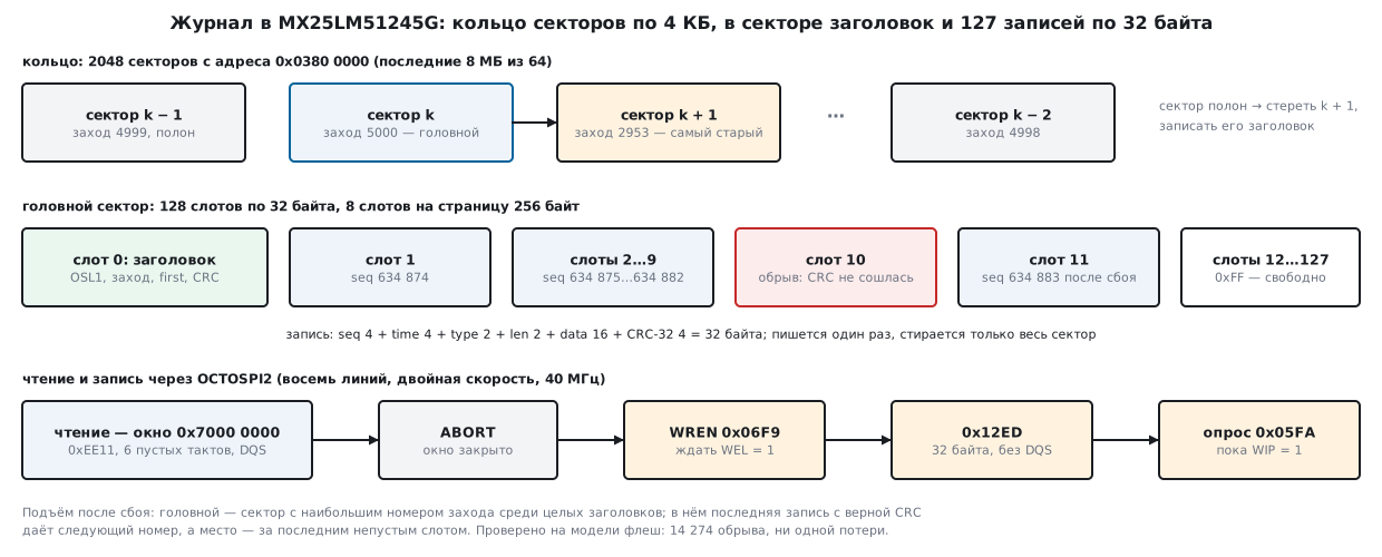
In 198х the B-U585I-IOT02A board learned to poll its sensors once a second. The polling lines have to be stored somewhere so that they survive a power-off. For that the board has a 64 MB MX25LM51245G flash connected to OCTOSPI2 with eight data lines. Here it becomes a circular log: 32-byte records with a CRC, a ring of 4 KB sectors, recovery after a power loss at any moment, and reading through the memory-mapped window.
Section 41в covered Quad-SPI on the F746: four lines, a single rate. Here there are eight lines, data moves on both clock edges, and the flash gets a second command "language". You have to switch it on yourself: after power-up the flash understands only single-line SPI.
Sources: the board package B-U585I-IOT02A_BSP 1.1.0 (files
b_u585i_iot02a_ospi.c|h, component mx25lm51245g, license
BSD-3-Clause), the STM32U5xx_DFP 2.2.1 pack (header stm32u585xx.h,
the HAL OSPI driver, the programmer algorithm .FLM), the reference manual
RM0456 (chapters 28 OCTOSPI, 29 OCTOSPIM and 32 DLYB). From this handbook:
41в — Quad-SPI and memory mapping, 42а — LittleFS on NOR flash,
11 — memory and Flash endurance, 204 — wear and reliability, 198а — a log in
the internal Flash on a battery, 2д — STM32U585 and the 160 MHz clock. The packs
contain no datasheet for the MX25LM51245G itself: everything about the chip here
comes from the headers and the driver code. QEMU has no U585, and the code was
not run on the board — it is checked on a PC, on models of the flash and the registers.
What it is called in the documentation
Original Meaning STR (single transfer rate) single rate: data on one clock edge DTR (double transfer rate) double rate: data on both edges OPI, SOPI, DOPI the eight-line protocol; SOPI — single rate, DOPI — double DQS (data strobe) data strobe: the flash itself marks when a byte is on the lines WIP (write in progress) status bit "a program or erase is in progress" configuration register 2 (CR2) configuration register 2: protocol and number of dummy cycles subsector what the board package calls the 4 KB erase unit bulk erase erasing the whole chip delay block (DLYB) delay block: shifts the data sampling point free-running clock (FRCK) the clock on the CLK pin runs all the time, not only during a command
198ц.1 The chip: how big it is and where it is connected
The sizes come from the board package header mx25lm51245g.h:
| What | Size | How many | Constant |
|---|---|---|---|
| whole flash | 64 MB (512 Mbit) | 1 | MX25LM51245G_FLASH_SIZE |
| erase block | 64 KB | 1024 | MX25LM51245G_SECTOR_64K |
| smallest erase | 4 KB | 16384 | MX25LM51245G_SUBSECTOR_4K |
| program page | 256 bytes | 262144 | MX25LM51245G_PAGE_SIZE |
The names are confusing. This header calls 64 KB a "sector" and 4 KB a
"subsector". The enumeration in the same file says the opposite:
MX25LM51245G_ERASE_4K — "4K size Sector erase", MX25LM51245G_ERASE_64K —
"64K size Block erase". The older version of this driver from the
32L4R9IDISCOVERY_BSP 1.0.0 package does the same: 4 KB is a "sector" and 64 KB a "block". From here on
in this section a sector is 4 KB, a block is 64 KB.
The flash sits on OCTOSPI2: clock — PF4, DQS — PF12, chip select — PI5, lines IO0–IO3 —
PF0–PF3, IO4–IO7 — PH9–PH12, all on alternate function AF5 (header
b_u585i_iot02a_ospi.h). The board package does not touch the OCTOSPIM pin manager:
after reset OCTOSPI2 is already routed to its own port 2 (RM0456, 29.4.3). The
OCTOSPI2 memory-mapped window starts at 0x7000 0000 (OCTOSPI2_BASE).
On this board OCTOSPI1 is used by another memory — the APS6408 PSRAM, which has its own
window at 0x9000 0000.
The programmer needs its own algorithm for this flash. The STM32U5xx_DFP 2.2.1 pack
has one — MX25LM51245G_STM32U585I_IOT02A.FLM. Its FlashDevice description
(parsed from the ELF in the check): start 0x7000 0000, size 0x0400 0000,
erase in 64 KB blocks, program chunk 4096 bytes, 0xFF after erase,
maximum program wait 10000 ms, erase wait 6000 ms.
198ц.2 After reset — SPI, in operation — eight DTR lines
After power-up the flash accepts "1-1-1" commands: instruction, address and
data on one line each (in the header: "Power on H/W default setting").
The protocol is changed by bits of register CR2 at address 0: SOPI = 0x01 — eight lines
at single rate, DOPI = 0x02 — eight lines at double rate; both zero — back to
SPI. The commands differ in all three modes:
| Action | SPI (1-1-1) | OPI DTR (8D-8D-8D) |
|---|---|---|
| write enable | 0x06 |
0x06F9 |
| read status | 0x05 |
0x05FA: address 0, 5 dummy cycles, 2 bytes, DQS |
| page program | 0x12 (4-byte address), 0x02 (3 bytes) |
0x12ED |
| erase 4 KB | 0x21, 0x20 |
0x21DE |
| erase 64 KB | 0xDC, 0xD8 |
0xDC23 |
| erase all | 0x60 |
0x609F |
| read | 0x0C, 8 dummy cycles (0x0B — 3 address bytes) |
0xEE11, 6 dummy cycles, DQS |
| write and read CR2 | 0x72, 0x71 |
0x728D, 0x718E |
| reset | 0x66, then 0x99 |
0x6699, then 0x9966 |
What changes in OPI:
- The command code is two bytes, and the second one is always the inverse of the first:
0x06becomes0x06F9,0x05becomes0x05FA. All 42 commands in the OPI part of the header are built this way (the check verifies each one). - The address is always 4 bytes. The package driver flatly refuses if you ask for 3 bytes in OPI. Even the status read in OPI goes with address 0.
- Dummy cycles wherever the flash answers: in DTR 5 cycles for registers
and 6 for memory reads (
mx25lm51245g_conf.h:DUMMY_CYCLES_REG_OCTAL_DTR= 5,DUMMY_CYCLES_READ_OCTAL_DTR= 6; for an SPI read — 8). The flash must wait the same number — so before DOPI is enabled, code0x07, "6 dummy cycles", is written to CR2 at address0x300. - DQS: in DTR the flash sends a strobe with its answer, and the controller uses it to catch the bytes. Reads go with DQS, page program goes without it.
How many cycles a read takes. An 8-bit instruction on one line is 8
cycles, 16 bits on eight lines — 2 cycles, in DTR — 1. A 32-bit address takes 32, 4 and 2
cycles. Data: 8 cycles per byte, 1 cycle and half a cycle. The frequency is 40 MHz, as
in the board package (calc198c.py):
| Read | Instruction | Address | Dummy | 32 bytes | 4 KB | Throughput |
|---|---|---|---|---|---|---|
SPI 0x0C |
8 | 32 | 8 | 304 cycles, 7.6 µs | 32816 cycles, 820.4 µs | 5 MB/s |
OPI STR 0xEC13 |
2 | 4 | 6 | 44 cycles, 1.1 µs | 4108 cycles, 102.7 µs | 40 MB/s |
OPI DTR 0xEE11 |
1 | 2 | 6 | 25 cycles, 0.625 µs | 2057 cycles, 51.43 µs | 80 MB/s |
Chip-select pauses between commands are not counted here, and RM0456 (28.4.5) warns that after the last byte the controller may output up to six extra cycles. On a 32-byte read six such cycles are almost a quarter of the whole command; on 4 KB they are invisible.
The enable sequence is the same as in BSP_OSPI_NOR_Init of the board package:
- Controller: OCTOSPI2 clock from the 160 MHz core —
OCTOSPISELafter reset is 00, SYSCLK (RM0456, 11.8.47), prescaler 4 — 40 MHz (package comment: "OctoSPI clock = 160MHz / ClockPrescaler = 40MHz"); memory type Micron, sizeDEVSIZE= 25 — 2^26 bytes = 64 MB, chip select stays high for at least 2 cycles between commands, FIFO threshold — 4 bytes. - DLYB delay block: tune the line length to one clock period (procedure — RM0456, 32.4.4) and take the phase at a quarter of that length — in the package this is an "emperic value", divider 4.
- Reset the flash with
0x66/0x99in all three languages — SPI, OPI STR and OPI DTR — and wait 100 ms (MX25LM51245G_RESET_MAX_TIME: "when SWreset during erase operation"). - Wait for WIP = 0, enable writing, CR2
0x300←0x07(6 dummy cycles), enable writing again, CR20←0x02(DOPI), wait 40 ms (MX25LM51245G_WRITE_REG_MAX_TIME). - Controller — to Macronix mode (
MTYP= 001: in DTR the bytes come in the order D1/D0, RM0456, 28.7.2) and with a quarter-cycle output delayDHQC. Check WIP already in DOPI and read CR2 back — it must contain0x02.
Controller setup and the delay block:
static void ctrl_setup(int macronix)
{
    OCTOSPI2->CR &= ~OCTOSPI_CR_EN;
    OCTOSPI2->DCR1 = (macronix ? OCTOSPI_DCR1_MTYP_0 : 0u)   /* 001 Macronix, 000 Micron */
                   | (25u << OCTOSPI_DCR1_DEVSIZE_Pos)        /* 2^(25 + 1) = 64 МБ */
                   | (1u << OCTOSPI_DCR1_CSHT_Pos);           /* NCS между командами — 2 такта */
    OCTOSPI2->DCR2 = 3u << OCTOSPI_DCR2_PRESCALER_Pos;        /* 160 МГц / 4 = 40 МГц */
    OCTOSPI2->DCR3 = 0u;
    OCTOSPI2->DCR4 = 0u;
    OCTOSPI2->CR = (OCTOSPI2->CR & ~OCTOSPI_CR_FTHRES) | (3u << OCTOSPI_CR_FTHRES_Pos);  /* порог 4 байта */
    OCTOSPI2->TCR = macronix ? OCTOSPI_TCR_DHQC : 0u;         /* выход сдвинут на четверть такта */
    OCTOSPI2->CR |= OCTOSPI_CR_EN;
    OCTOSPI2->DCR1 |= OCTOSPI_DCR1_FRCK;                      /* такт всегда идёт — после EN */
}
static int dlyb_tune(void)
{
    uint32_t unit, lng = 0u, n;

    DLYB_OCTOSPI2->CR = DLYB_CR_DEN | DLYB_CR_SEN;
    for (unit = 0u; unit < 128u; unit++) {
        DLYB_OCTOSPI2->CFGR = 12u | (unit << DLYB_CFGR_UNIT_Pos);   /* все 12 ячеек */
        uint32_t t0 = mx_now_ms();
        while (!(DLYB_OCTOSPI2->CFGR & DLYB_CFGR_LNGF)) {
            MX_POLL();
            if (mx_now_ms() - t0 > 255u)
                return -1;
        }
        lng = (DLYB_OCTOSPI2->CFGR & DLYB_CFGR_LNG_Msk) >> DLYB_CFGR_LNG_Pos;
        if ((lng & 0x7FFu) != 0u && (lng & 0xC00u) != 0xC00u)
            break;                                            /* линия длиной в один такт */
    }
    if (unit == 128u)
        return -1;
    for (n = 10u; n > 0u && (lng >> n) == 0u; n--) {
    }
    if (n == 0u)
        return -1;
    DLYB_OCTOSPI2->CFGR = (n / 4u) | (unit << DLYB_CFGR_UNIT_Pos);  /* SEL и UNIT пишутся при SEN = 1 */
    DLYB_OCTOSPI2->CR = DLYB_CR_DEN;                              /* SEN = 0: выход на выбранной фазе */
    OCTOSPI2->CR |= OCTOSPI_CR_ABORT;
    while (OCTOSPI2->CR & OCTOSPI_CR_ABORT)
        MX_POLL();
    OCTOSPI2->DCR1 &= ~OCTOSPI_DCR1_FRCK;
    return 0;
}
The whole enable sequence:
int mx_init(void)
{
    uint8_t cr2[2];
    uint8_t v;

    pins();
    RCC->AHB2ENR2 |= RCC_AHB2ENR2_OCTOSPI2EN;
    RCC->AHB2RSTR2 |= RCC_AHB2RSTR2_OCTOSPI2RST;
    RCC->AHB2RSTR2 &= ~RCC_AHB2RSTR2_OCTOSPI2RST;
    dtr = 0;
    ctrl_setup(0);
    if (dlyb_tune() != 0)
        return -1;
    /* Флеш не сбрасывается вместе с МК: она может ждать команды в SPI, OPI STR или OPI DTR.
       Сброс шлётся на всех трёх — поймёт тот, на котором она сейчас. */
    if (cmd(FM_WRITE, I_1, MX_SPI_RESET_ENABLE, 0u, 0u, 0, 0, 0u) || cmd(FM_WRITE, I_1, MX_SPI_RESET_MEMORY, 0u, 0u, 0, 0, 0u)
        || cmd(FM_WRITE, I_8STR, MX_OPI_RESET_ENABLE, 0u, 0u, 0, 0, 0u) || cmd(FM_WRITE, I_8STR, MX_OPI_RESET_MEMORY, 0u, 0u, 0, 0, 0u)
        || cmd(FM_WRITE, I_8DTR, MX_OPI_RESET_ENABLE, 0u, 0u, 0, 0, 0u) || cmd(FM_WRITE, I_8DTR, MX_OPI_RESET_MEMORY, 0u, 0u, 0, 0, 0u))
        return -1;
    delay_ms(MX_T_RESET_MS);                                  /* сброс мог прервать стирание */
    if (poll(MX_SR_WIP, 0u, MX_T_POLL_MS) != 0)
        return -1;
    v = MX_CR2_DC_6;                                          /* CR2 0x300: 6 пустых тактов */
    if (write_enable() || cmd(FM_WRITE, I_1 | A_1 | D_1, MX_SPI_WRITE_CFG2, 0u, MX_CR2_REG3, 0, &v, 1u))
        return -1;
    v = MX_CR2_DOPI;                                          /* CR2 0x000: DOPI */
    if (write_enable() || cmd(FM_WRITE, I_1 | A_1 | D_1, MX_SPI_WRITE_CFG2, 0u, MX_CR2_REG1, 0, &v, 1u))
        return -1;
    delay_ms(MX_T_WRITE_REG_MS);
    ctrl_setup(1);
    dtr = 1;
    if (poll(MX_SR_WIP, 0u, MX_T_POLL_MS) != 0
        || cmd(FM_READ, I_8DTR | A_8DTR | D_8DTR | DQS, MX_OPI_READ_CFG2, MX_DUMMY_REG_DTR, MX_CR2_REG1, cr2, 0, 2u))
        return -1;
    return cr2[0] == MX_CR2_DOPI ? 0 : -1;
}
FRCK is set the same way as in the package: HAL enables the free-running clock on every
configuration, the delay block switches it off while tuning, and the second
configuration for Macronix switches it on again.
198ц.3 A command through registers: program, erase, wait
Any indirect-mode command is FMODE in CR, the length in DLR, the phases
in CCR, the dummy cycles in TCR, the code in IR and the address in AR. It starts on
the last write that is needed (RM0456, 28.4.9): on the write to AR if there is an address;
on the write to IR if there is no address and no data is transferred; on the first write to
DR if the program transfers the data. That is why the order in cmd is exactly this:
static int cmd(uint32_t fmode, uint32_t ccr, uint32_t ir, uint32_t dcyc, uint32_t addr,
               uint8_t *rx, const uint8_t *tx, uint32_t n)
{
    if (wait_idle() != 0)
        return -1;
    OCTOSPI2->CR = (OCTOSPI2->CR & ~OCTOSPI_CR_FMODE) | fmode;
    if (n)
        OCTOSPI2->DLR = n - 1u;
    OCTOSPI2->CCR = ccr;
    OCTOSPI2->TCR = (OCTOSPI2->TCR & ~OCTOSPI_TCR_DCYC) | dcyc;
    OCTOSPI2->IR = ir;
    if (ccr & OCTOSPI_CCR_ADMODE)
        OCTOSPI2->AR = addr;
    for (uint32_t i = 0; tx && i < n; i++) {
        if (wait_sr(OCTOSPI_SR_FTF, MX_T_POLL_MS) != 0)
            return -1;
        MX_DR8 = tx[i];
    }
    for (uint32_t i = 0; rx && i < n; i++) {
        if (wait_sr(OCTOSPI_SR_FTF | OCTOSPI_SR_TCF, MX_T_POLL_MS) != 0)
            return -1;
        rx[i] = MX_DR8;
    }
    if (wait_sr(OCTOSPI_SR_TCF, MX_T_POLL_MS) != 0)
        return -1;
    OCTOSPI2->FCR = OCTOSPI_FCR_CTCF;
    return 0;
}
The CPU does not need to wait for WIP: in automatic status-polling mode the controller
itself sends a status read every PIR cycles and sets SMF when
(status & mask) == match; with APMS it then stops by itself.
In DTR the status is read as two bytes — this is what the package driver does:
static int poll(uint32_t mask, uint32_t match, uint32_t ms)
{
    uint32_t ccr = dtr ? (I_8DTR | A_8DTR | D_8DTR | DQS) : (I_1 | D_1);

    if (wait_idle() != 0)
        return -1;
    OCTOSPI2->PSMAR = match;
    OCTOSPI2->PSMKR = mask;
    OCTOSPI2->PIR = 0x10u;                                    /* MX25LM51245G_AUTOPOLLING_INTERVAL_TIME */
    OCTOSPI2->CR = (OCTOSPI2->CR & ~(OCTOSPI_CR_FMODE | OCTOSPI_CR_PMM)) | FM_POLL | OCTOSPI_CR_APMS;
    OCTOSPI2->DLR = dtr ? 1u : 0u;                            /* в DTR статус читается двумя байтами */
    OCTOSPI2->CCR = ccr;
    OCTOSPI2->TCR = (OCTOSPI2->TCR & ~OCTOSPI_TCR_DCYC) | (dtr ? MX_DUMMY_REG_DTR : 0u);
    OCTOSPI2->IR = dtr ? MX_OPI_READ_STATUS : MX_SPI_READ_STATUS;
    if (dtr)
        OCTOSPI2->AR = 0u;
    if (wait_sr(OCTOSPI_SR_SMF, ms) != 0)
        return -1;
    OCTOSPI2->FCR = OCTOSPI_FCR_CSMF;
    return 0;
}
static int write_enable(void)
{
    if (dtr ? cmd(FM_WRITE, I_8DTR | NODATA_DTR, MX_OPI_WRITE_ENABLE, 0u, 0u, 0, 0, 0u)
            : cmd(FM_WRITE, I_1, MX_SPI_WRITE_ENABLE, 0u, 0u, 0, 0, 0u))
        return -1;
    return poll(MX_SR_WEL, MX_SR_WEL, MX_T_POLL_MS);          /* дождаться WEL = 1 */
}
Programming and erasing follow one scheme: wait until the flash is free, enable writing and wait for the WEL bit, issue the command, wait for WIP again. The board package sends WREN before every page and before every erase — and so does this code.
int mx_prog(uint32_t addr, const void *buf, uint32_t n)
{
    if (n == 0u || n > 256u || (addr & 1u) || (n & 1u) || (addr & 255u) + n > 256u)
        return -1;
    if (poll(MX_SR_WIP, 0u, MX_T_POLL_MS) || write_enable()
        || cmd(FM_WRITE, I_8DTR | A_8DTR | D_8DTR, MX_OPI_PAGE_PROG, 0u, addr, 0, buf, n))
        return -1;
    return poll(MX_SR_WIP, 0u, MX_T_POLL_MS);
}
int mx_erase4k(uint32_t addr)
{
    if (addr & 4095u)
        return -1;
    if (poll(MX_SR_WIP, 0u, MX_T_POLL_MS) || write_enable()
        || cmd(FM_WRITE, I_8DTR | A_8DTR | NODATA_DTR, MX_OPI_ERASE_4K, 0u, addr, 0, 0, 0u))
        return -1;
    return poll(MX_SR_WIP, 0u, MX_T_POLL_MS);
}
The parity check in mx_prog is not nitpicking. RM0456 (28.4.9): in indirect
mode on eight DTR lines without DQS "the given starting address and the data
length must be even". Page program goes exactly without DQS.
How long to wait. The maximum times in the header: erase 4 KB — 400 ms,
64 KB — 1000 ms, the whole flash — 460000 ms, that is almost 8 minutes; register
write — 40 ms. In the driver version from the 32L4R9IDISCOVERY_BSP package the same
figures are different: 400 ms for 4 KB, 2000 for 64 KB and 300000 for the whole chip. Neither
gives a page program time; the board package waits for WIP with the HAL timeout — 5 s
(HAL_OSPI_TIMEOUT_DEFAULT_VALUE), and poll waits the same.
NODATA_DTR has its own story: HAL sets the DDTR bit for commands without data too,
if DHQC is on and the instruction goes in DTR. The code repeats this so that
the frames match the package bit for bit.
198ц.4 A circular log: slot, header, ring
NOR flash is programmed only from 1 to 0: after an erase all bytes are 0xFF, programming
clears bits, and only erasing a whole sector can bring a 1 back. Hence
the design of the log:
- a slot is 32 bytes. Exactly 8 of them fit in a 256-byte page: a write never crosses a page boundary. The length and the address are even — the DTR rule is met automatically;
- a 4 KB sector is 128 slots: slot 0 is the header, 1…127 are records;
- the header stores the pass number
sseq: the sector written for thesseq-th time is(sseq − 1) % nsect. And the number of the sector's first record; - a record is a number, a time, a type, up to 16 bytes of data and a CRC-32 over the first 28
bytes. The CRC is the common one with polynomial
0xEDB88320: for the string "123456789" it is0xCBF43926, as it should be.
/* Раздел 198ц: журнал по кругу во внешней NOR-флеш.
   Сектор 4 КБ = 128 слотов по 32 байта: слот 0 — заголовок сектора, 1…127 — записи.
   Флеш видна через три функции: чтение, запись в пределах страницы и стирание сектора —
   одинаково для MX25LM51245G на B-U585I-IOT02A и для модели флеш на ПК. */
#ifndef OSLOG_H
#define OSLOG_H

#include <stdint.h>

#define OSLOG_PAGE    256u                        /* страница записи MX25LM51245G */
#define OSLOG_SECTOR  4096u                       /* наименьшее стирание — 4 КБ */
#define OSLOG_SLOT    32u                         /* запись и заголовок — по 32 байта */
#define OSLOG_SLOTS   (OSLOG_SECTOR / OSLOG_SLOT) /* 128 слотов в секторе */
#define OSLOG_DATA    16u                         /* полезных байт в записи */
#define OSLOG_MAGIC   0x314C534Fu                 /* "OSL1" */

struct oslog_rec {                  /* 32 байта: 8 записей на страницу, 127 на сектор */
    uint32_t seq;                   /* номер записи: 1, 2, 3… без пропусков */
    uint32_t time;                  /* время приложения, например секунды RTC */
    uint16_t type;                  /* что за запись — решает приложение */
    uint16_t len;                   /* сколько байт data занято */
    uint8_t  data[OSLOG_DATA];
    uint32_t crc;                   /* CRC-32 первых 28 байт */
};

struct oslog_hdr {                  /* 32 байта в слоте 0 каждого сектора */
    uint32_t magic;
    uint32_t sseq;                  /* номер захода: 1, 2, 3…; сектор = (sseq - 1) % nsect */
    uint32_t first;                 /* seq первой записи, которая ляжет в сектор */
    uint8_t  pad[16];               /* 0xFF */
    uint32_t crc;                   /* CRC-32 первых 28 байт */
};

struct oslog_flash {
    int (*read)(uint32_t addr, void *buf, uint32_t n);
    int (*prog)(uint32_t addr, const void *buf, uint32_t n);  /* не через край страницы */
    int (*erase)(uint32_t addr);                              /* сектор 4 КБ */
};

struct oslog {
    const struct oslog_flash *f;
    uint32_t base;                  /* адрес области журнала во флеш, кратен 4 КБ */
    uint32_t nsect;                 /* секторов в кольце, не меньше 2 */
    uint32_t head;                  /* сектор, в который пишем */
    uint32_t sseq;                  /* его номер захода */
    uint32_t slot;                  /* следующий свободный слот, 128 — сектор полон */
    uint32_t next;                  /* seq следующей записи */
    uint32_t torn;                  /* испорченных слотов в текущем секторе при подъёме */
    uint32_t skipped;               /* слотов, пропущенных из-за ошибки проверки записи */
};

uint32_t oslog_crc32(const void *p, uint32_t n);
int oslog_mount(struct oslog *l);
int oslog_append(struct oslog *l, uint32_t time, uint16_t type, const void *data, uint16_t len);
uint32_t oslog_walk(const struct oslog *l, int (*cb)(const struct oslog_rec *r, void *ctx), void *ctx);

#endif
A slot is written once and read back right away. If it does not match, the slot
is skipped: it stays corrupted, and the record goes into the next one.
Moving to a new sector always goes through an erase, even if the sector looks
clean: an erase torn halfway can leave a sector half
0xFF, and by its look you cannot tell.
static int rotate(struct oslog *l)
{
    uint32_t n = (l->head + 1u) % l->nsect;
    struct oslog_hdr h, chk;

    memset(&h, 0xFF, sizeof h);
    h.magic = OSLOG_MAGIC;
    h.sseq = l->sseq + 1u;
    h.first = l->next;
    h.crc = oslog_crc32(&h, 28u);
    if (l->f->erase(slot_addr(l, n, 0u)) != 0 || l->f->prog(slot_addr(l, n, 0u), &h, sizeof h) != 0
        || l->f->read(slot_addr(l, n, 0u), &chk, sizeof chk) != 0 || memcmp(&h, &chk, sizeof h) != 0)
        return -1;
    l->head = n;
    l->sseq = h.sseq;
    l->slot = 1u;
    return 0;
}
int oslog_append(struct oslog *l, uint32_t time, uint16_t type, const void *data, uint16_t len)
{
    struct oslog_rec r, chk;

    if (len > OSLOG_DATA)
        return -1;
    memset(&r, 0, sizeof r);
    r.seq = l->next;
    r.time = time;
    r.type = type;
    r.len = len;
    memcpy(r.data, data, len);
    r.crc = oslog_crc32(&r, 28u);
    for (int tries = 0; tries < 4; tries++) {
        if (l->slot >= OSLOG_SLOTS && rotate(l) != 0)
            return -1;
        uint32_t a = slot_addr(l, l->head, l->slot++);
        if (l->f->prog(a, &r, sizeof r) == 0 && l->f->read(a, &chk, sizeof chk) == 0
            && memcmp(&r, &chk, sizeof r) == 0) {
            l->next++;
            return 0;
        }
        l->skipped++;
    }
    return -1;
}
In the firmware the ring is 2048 sectors, 8 MB at the end of the flash, from 0x0380 0000.
That is 260096 records: once a minute it is half a year of history, 180.6 days.
198ц.5 Power loss: recovery and a check on a model
After reset the log remembers nothing and rebuilds everything from the flash:
- Read the headers of all sectors. The head sector is the one with the largest pass number among the intact ones (magic, CRC and a number that agrees with the position).
- No intact headers — a blank flash: erase sector 0 and start from it.
- In the head sector go through all 127 slots. The last record with a valid CRC gives the next number, the free space is right after the last non-empty slot. Corrupted slots are not touched, they are only counted.
int oslog_mount(struct oslog *l)
{
    struct oslog_hdr h;
    struct oslog_rec r;
    uint32_t best = 0u, first = 1u;

    l->head = 0u;
    for (uint32_t i = 0; i < l->nsect; i++) {
        if (l->f->read(slot_addr(l, i, 0u), &h, sizeof h) != 0)
            return -1;
        if (hdr_ok(l, &h, i) && h.sseq > best) {
            best = h.sseq;
            first = h.first;
            l->head = i;
        }
    }
    l->torn = 0u;
    l->skipped = 0u;
    if (best == 0u) {                                  /* чистая флеш: начать с сектора 0 */
        l->head = l->nsect - 1u;
        l->sseq = 0u;
        l->next = 1u;
        return rotate(l);
    }
    l->sseq = best;
    l->next = first;
    l->slot = 1u;
    for (uint32_t s = 1u; s < OSLOG_SLOTS; s++) {
        if (l->f->read(slot_addr(l, l->head, s), &r, sizeof r) != 0)
            return -1;
        if (blank(&r))
            continue;
        l->slot = s + 1u;
        if (rec_ok(&r) && r.seq >= l->next)
            l->next = r.seq + 1u;
        else
            l->torn++;
    }
    return 0;
}
The walk from the newest record to the oldest (oslog_walk) goes back sector by sector while
the pass numbers are consecutive, and returns only records with a valid CRC and strictly
decreasing numbers. This way neither a torn slot nor the records
of a half-erased old sector get into the output.
Flash model on the PC (sim.c, gcc 12.2.0 in the stm-sys:1 image): 4 sectors
of 4 KB; erase gives 0xFF; programming is only an AND with the data (1 → 0);
counted as program errors are a write across a page boundary, an odd address
or length, and a write over already written data. The run writes 1574 records —
a little over three laps — and before every operation makes a copy of the flash, tears
the operation halfway on the copy, recovers the log, appends another 200
records and recovers again. The main run meanwhile continues without
a tear. How a write is torn: the first k bytes are intact (k = 0, 1, 2, 15, 16, 27, 30,
31), in byte k at least one bit did not have time to clear; one more case —
the record went in completely, but power was lost before the flash answered. How an
erase is torn: 0xFF is already in the first 0, 32, 2048, 4064 or 4095 bytes, or in
every second page.
What the check requires after every tear: the next number is exactly after
the last record that oslog_append managed to confirm (or after
one that went in completely); the walk returns, without gaps and with correct data, at least
two full sectors; after 200 new records and a second recovery — the same.
| Run | Result |
|---|---|
| main: 1574 records, 4 sectors | 1587 program commands, 13 erases, 431 records in the ring — from the 1144th to the 1574th |
| tears | 14274 (14202 during program, 72 during erase), of them 1586 "went in completely", 0 failed |
| flash rule violations | 0 |
| stuck bit in a slot | the record moved to the next slot, after recovery 1 corrupted slot, 432 records |
To make sure the check catches errors, run198c.sh builds three
broken copies of oslog.c:
| Fault | What happened |
|---|---|
| a record counts as intact without a CRC check | 7840 of 14274 tears failed |
| moving to a sector without an erase | the log does not start on a flash with garbage: mount_fresh rc=-1 |
| the head is the first intact header, not the one with the largest number | all 14274 failed |
198ц.6 The read window, the firmware and endurance
The easiest way to read the log is through the window: after mx_map the flash at
0x7000 0000 is ordinary memory, and a memcpy from it turns into 0xEE11 commands
by itself. RM0456 (28.4.11) advises against writing through the window: "It is not
recommended to program the flash memory using the memory-mapped writes".
That is why WCCR = 0: a write to the window with DMODE = 000 is an AHB bus error
(RM0456, 28.4.17), and an accidental write will not pass silently.
int mx_map(void)
{
    if (wait_idle() != 0)
        return -1;
    OCTOSPI2->CR &= ~OCTOSPI_CR_FMODE;
    OCTOSPI2->CCR = I_8DTR | A_8DTR | D_8DTR | DQS;
    OCTOSPI2->TCR = OCTOSPI_TCR_DHQC | MX_DUMMY_READ_DTR;
    OCTOSPI2->IR = MX_OPI_READ_DTR;
    OCTOSPI2->WCCR = 0u;
    OCTOSPI2->CR |= FM_MAP;
    return 0;
}
int mx_unmap(void)                                /* ABORT: упреждение остановлено, FIFO пуст */
{
    OCTOSPI2->CR |= OCTOSPI_CR_ABORT;
    uint32_t t0 = mx_now_ms();
    while (OCTOSPI2->CR & OCTOSPI_CR_ABORT) {
        MX_POLL();
        if (mx_now_ms() - t0 > MX_T_POLL_MS)
            return -1;
    }
    OCTOSPI2->CR &= ~OCTOSPI_CR_FMODE;
    return wait_idle();
}
While a prefetch is running in the window, BUSY does not drop and CCR cannot
be changed. Before a write the window is closed with ABORT: it stops the prefetch
and clears the FIFO, so that after the write no stale bytes are read from the window.
The log glue code:
/* Раздел 198ц: чтение журнала — через окно отображения, запись и стирание — косвенным режимом. */
#include <stdint.h>
#include <string.h>
#include "mx_ospi.h"
#include "log_u585.h"

static int f_read(uint32_t a, void *buf, uint32_t n)
{
    memcpy(buf, (const void *)(uintptr_t)(MX_MAP_BASE + a), n);   /* обычное чтение памяти */
    return 0;
}

static int f_prog(uint32_t a, const void *buf, uint32_t n)
{
    int r = mx_unmap();                   /* пока идёт запись, окна нет */
    if (r == 0)
        r = mx_prog(a, buf, n);
    if (mx_map() != 0)
        r = -1;
    return r;
}

static int f_erase(uint32_t a)
{
    int r = mx_unmap();
    if (r == 0)
        r = mx_erase4k(a);
    if (mx_map() != 0)
        r = -1;
    return r;
}

static const struct oslog_flash ospi_flash = { f_read, f_prog, f_erase };

int log_open(struct oslog *l)
{
    if (mx_init() != 0 || mx_map() != 0)
        return -1;
    l->f = &ospi_flash;
    l->base = LOG_BASE;
    l->nsect = LOG_NSECT;
    return oslog_mount(l);
}
And the firmware itself — one record per minute; the 160 MHz clock is the function
clock_160mhz from section 2д, SysTick counts milliseconds for
the driver timeouts:
int main(void)
{
    static struct oslog l;
    uint32_t next, minutes = 0u;

    clock_160mhz();
    SysTick->LOAD = 160000u - 1u;                             /* 160 МГц / 160 000 = 1 кГц */
    SysTick->VAL = 0u;
    SysTick->CTRL = SysTick_CTRL_CLKSOURCE_Msk | SysTick_CTRL_TICKINT_Msk | SysTick_CTRL_ENABLE_Msk;
    if (log_open(&l) != 0)
        for (;;) {
        }
    next = ms;
    for (;;) {
        if ((int32_t)(ms - next) >= 0) {
            next += 60000u;
            minutes++;
            (void)oslog_append(&l, ms / 1000u, 1u, &minutes, sizeof minutes);
        }
        __WFI();
    }
}
The driver on a register model (mxmodel.c). mx_ospi.c and log_u585.c
are built on the PC unchanged; OCTOSPI2, DLYB_OCTOSPI2, RCC and the ports are
structures from stm32u585xx.h. In the driver's wait loops (MX_POLL) the model
steps: it decodes the command from CCR, TCR, IR, AR, DLR, checks the frame against
the package rules (lines, DTR, 16-bit code, second byte the inverse of the first,
dummy cycles, DQS, controller memory type) and executes it on the flash model:
WEL, WIP, CR2, switching SPI → DOPI, programming 1 → 0, erase. A command in
a "foreign" language is not understood by the flash — the model skips it.
| Experiment on the model | Result |
|---|---|
| the MCU reset finds the flash in SPI, OPI STR, OPI DTR with an erase in progress | in all three mx_init = 0, CR2 0x02 and 0x07, 4 reset commands in foreign languages skipped each time, 0 errors |
| the log on top of the driver: 300 records and a fresh recovery | 302 page programs (300 + 2 headers), 304 WREN, after recovery the next number is 301, 300 in the walk |
| fault: no reset in the OPI DTR language | the flash never leaves DTR, mx_init = −1 |
| fault: program and erase without WREN | the model catches "pp_without_wel" and "erase_without_wel" |
Built with armclang 6.24, Cortex-M33 with FPU, -std=c11 -Os -Wall -Wextra
-pedantic — no warnings. Without linking: the vectors and startup code
come from the application project.
| File | Code, bytes | Constants, bytes |
|---|---|---|
oslog.c |
1210 | 56 |
mx_ospi.c |
1802 | 88 |
log_u585.c |
156 | 44 |
app_u585.c |
156 | 24 |
start2f.c (clock, 2д) |
140 | 8 |
| total | 3464 | 220 |
Recovery over the bus. 2048 headers and 127 slots are 2175 reads of 32 bytes, each a separate 25-cycle command: 54375 cycles, 1.36 ms at 40 MHz without pauses and bus delays.
Endurance. One record per minute, 127 records per sector — a sector fills up in 127 minutes. In a ring of 2048 sectors each one is erased once every 2048 × 127 = 260096 minutes — 2.02 times a year. If you give the log the whole flash, 16384 sectors, it is 0.25 times a year and almost four years of history (1445 days). How many erase cycles the MX25LM51245G withstands is not written in the packs — the chip's datasheet is not there, so there will be no years here: take the number of cycles from the datasheet and divide it by 2.02. For comparison, the internal Flash of the F103 in 198а has an endurance of 10000 cycles — against it the log wore it out by half a percent a year. What else limits the lifetime — data retention and temperature — is covered in 204.
198ц.7 Pitfalls
- The flash is not reset together with the MCU. After a restart from the button or the debugger it stays in DOPI, or even in the middle of an erase, and does not understand SPI commands. That is why the reset is sent in all three languages, followed by a 100 ms wait. On the model, the fault without a reset in the DTR language leaves the flash in DTR forever.
- Odd length in DTR. Without DQS the address and length of an indirect command must be even (RM0456, 28.4.9). A 32-byte slot meets this rule by itself; a write of "however many bytes came in" does not.
- A write across a page boundary. One command programs 1 to 256 bytes within
a page (the driver says: "Range 1 ~ MX25LM51245G_PAGE_SIZE"), and
the board package splits a long write into pages itself. What the flash does with
a write across the boundary is not stated in the package —
mx_progdoes not allow it. - A register write while BUSY = 1 is lost silently. RM0456 (28.4.15): "any
register write operation when BUSY = 1 has no effect and is not signaled
with an error response". That is why
cmd,pollandmx_mapfirst wait forBUSY= 0, and the window is closed withABORTbefore a write. - Reading the window at the wrong time. With mapping off, any read of the window
is an AHB bus error, and beyond
DEVSIZEbut inside 256 MB the core gets a HardFault (RM0456, 28.4.11 and 28.4.17). A debugger with a memory window open at0x7000 0000hits this first. - Byte order in DTR. Macronix needs
MTYP= 001, otherwise the bytes of a pair are swapped: "it reads, but the wrong thing". In SPI the package keeps the Micron mode —MTYPis changed together with the switch to DOPI. - SSHIFT and DHQC. With
DDTR= 1 the sampling shiftSSHIFTmust be cleared;DHQCmust not be set with prescaler 0 (RM0456, 28.4.5). - A "sector" in one file is not a "sector" in another. Different driver versions name 4 KB and 64 KB differently, and their maximum times differ too: 64 KB — 1000 or 2000 ms, the whole flash — 460 or 300 s.
- A partially erased sector looks clean. A torn erase can
leave
0xFFalmost everywhere. You cannot decide "the sector is empty" by its look — erase before every pass. - A big ring means a long recovery. All headers are read: for 2048 sectors it is 1.36 ms on the bus alone, for the whole flash, 16384 sectors, — 10.32 ms.
198ц.8 Summary
- MX25LM51245G: 64 MB, 64 KB blocks (1024), 4 KB sectors (16384), 256-byte page
(262144); OCTOSPI2, window at
0x7000 0000, pins PF0–PF4, PF12, PH9–PH12, PI5 on AF5. - After reset — SPI; CR2
0x300←0x07(6 dummy cycles), CR20←0x02(DOPI). In OPI the code is two bytes with an inverse, the address is 4 bytes, status is read with address 0 and 5 dummy cycles, read0xEE11with 6 dummy cycles and DQS. - Reading 32 bytes at 40 MHz: 304 cycles in SPI, 44 in OPI STR, 25 in OPI DTR; throughput up to 5, 40 and 80 MB/s.
- Program: WREN and WEL,
0x12ED, WIP polled by the controller; in DTR without DQS — even address and length. Erasing 4 KB takes up to 400 ms. - Log: 32-byte slot, 127 records per sector, a header with the pass number; recovery — the largest pass and the last valid CRC. 14274 tears on the model — not a single confirmed record lost.
- The firmware is 3464 bytes of code; a ring of 2048 sectors holds 260096 records, half a year at one per minute, 2.02 sector erases a year.
Full sources
mx_ospi.c — MX25LM51245G on OCTOSPI2 through registers.
/* Раздел 198ц: MX25LM51245G на OCTOSPI2 — регистрами. Порядок и значения повторяют
   b_u585i_iot02a_ospi.c из пакета платы: такт 160 МГц / 4 = 40 МГц, CSHT 2 такта,
   блок задержки DLYB, сброс флеш на трёх «языках», CR2: 6 пустых тактов, затем DOPI. */
#include "stm32u5xx.h"
#include "mx_ospi.h"

#ifndef MX_POLL
#define MX_POLL()                              /* на ПК здесь шагает модель */
#endif
#ifndef MX_DR8
#define MX_DR8 (*(volatile uint8_t *)&OCTOSPI2->DR)    /* байтовый доступ к младшему байту DR */
#endif

/* Поля CCR: линии и скорость фаз инструкции (I), адреса (AD) и данных (D) */
#define I_1      OCTOSPI_CCR_IMODE_0                          /* 1 линия, 8 бит */
#define I_8DTR   (OCTOSPI_CCR_IMODE_2 | OCTOSPI_CCR_IDTR | OCTOSPI_CCR_ISIZE_0)   /* 8 линий, 16 бит */
#define I_8STR   (OCTOSPI_CCR_IMODE_2 | OCTOSPI_CCR_ISIZE_0)
#define A_1      (OCTOSPI_CCR_ADMODE_0 | OCTOSPI_CCR_ADSIZE)  /* 1 линия, 32 бита */
#define A_8DTR   (OCTOSPI_CCR_ADMODE_2 | OCTOSPI_CCR_ADDTR | OCTOSPI_CCR_ADSIZE)
#define D_1      OCTOSPI_CCR_DMODE_0
#define D_8DTR   (OCTOSPI_CCR_DMODE_2 | OCTOSPI_CCR_DDTR)
#define DQS      OCTOSPI_CCR_DQSE
#define NODATA_DTR OCTOSPI_CCR_DDTR     /* HAL ставит DDTR и командам без данных, когда включён DHQC */

#define FM_WRITE 0u
#define FM_READ  OCTOSPI_CR_FMODE_0
#define FM_POLL  OCTOSPI_CR_FMODE_1
#define FM_MAP   OCTOSPI_CR_FMODE

static int dtr;                                   /* флеш уже в OPI DTR */

static void pins(void)
{
    /* PF0–PF3 IO0–IO3, PF4 CLK, PF12 DQS, PH9–PH12 IO4–IO7, PI5 NCS — все AF5 */
    static GPIO_TypeDef *const port[] = { GPIOF, GPIOF, GPIOF, GPIOF, GPIOF, GPIOF,
                                          GPIOH, GPIOH, GPIOH, GPIOH, GPIOI };
    static const uint8_t pin[]  = { 0, 1, 2, 3, 4, 12, 9, 10, 11, 12, 5 };
    static const uint8_t pull[] = { 0, 0, 0, 0, 0, 1, 0, 0, 0, 0, 1 };  /* подтяжка вверх: DQS и NCS */

    RCC->AHB2ENR1 |= RCC_AHB2ENR1_GPIOFEN | RCC_AHB2ENR1_GPIOHEN | RCC_AHB2ENR1_GPIOIEN;
    for (uint32_t i = 0; i < sizeof pin; i++) {
        GPIO_TypeDef *g = port[i];
        uint32_t p = pin[i];
        g->OSPEEDR |= 3u << (2u * p);                             /* очень высокая скорость */
        g->PUPDR = (g->PUPDR & ~(3u << (2u * p))) | ((uint32_t)pull[i] << (2u * p));
        g->AFR[p >> 3] = (g->AFR[p >> 3] & ~(15u << (4u * (p & 7u)))) | (5u << (4u * (p & 7u)));
        g->MODER = (g->MODER & ~(3u << (2u * p))) | (2u << (2u * p));   /* альтернативная функция */
    }
}

static int wait_sr(uint32_t flag, uint32_t ms)
{
    uint32_t t0 = mx_now_ms();
    for (;;) {
        MX_POLL();
        if (OCTOSPI2->SR & flag)
            return 0;
        if (mx_now_ms() - t0 > ms)
            return -1;
    }
}

static int wait_idle(void)                        /* BUSY = 0 — можно менять CCR, TCR, IR */
{
    uint32_t t0 = mx_now_ms();
    for (;;) {
        MX_POLL();
        if (!(OCTOSPI2->SR & OCTOSPI_SR_BUSY))
            return 0;
        if (mx_now_ms() - t0 > MX_T_POLL_MS)
            return -1;
    }
}

/* Одна команда в косвенном режиме. Старт: запись AR, если есть адрес; иначе запись IR;
   при передаче данных — первая запись в DR (RM0456, 28.4.9). */
static int cmd(uint32_t fmode, uint32_t ccr, uint32_t ir, uint32_t dcyc, uint32_t addr,
               uint8_t *rx, const uint8_t *tx, uint32_t n)
{
    if (wait_idle() != 0)
        return -1;
    OCTOSPI2->CR = (OCTOSPI2->CR & ~OCTOSPI_CR_FMODE) | fmode;
    if (n)
        OCTOSPI2->DLR = n - 1u;
    OCTOSPI2->CCR = ccr;
    OCTOSPI2->TCR = (OCTOSPI2->TCR & ~OCTOSPI_TCR_DCYC) | dcyc;
    OCTOSPI2->IR = ir;
    if (ccr & OCTOSPI_CCR_ADMODE)
        OCTOSPI2->AR = addr;
    for (uint32_t i = 0; tx && i < n; i++) {
        if (wait_sr(OCTOSPI_SR_FTF, MX_T_POLL_MS) != 0)
            return -1;
        MX_DR8 = tx[i];
    }
    for (uint32_t i = 0; rx && i < n; i++) {
        if (wait_sr(OCTOSPI_SR_FTF | OCTOSPI_SR_TCF, MX_T_POLL_MS) != 0)
            return -1;
        rx[i] = MX_DR8;
    }
    if (wait_sr(OCTOSPI_SR_TCF, MX_T_POLL_MS) != 0)
        return -1;
    OCTOSPI2->FCR = OCTOSPI_FCR_CTCF;
    return 0;
}

/* Автоматический опрос статуса: контроллер сам читает регистр, пока (SR & mask) != match. */
static int poll(uint32_t mask, uint32_t match, uint32_t ms)
{
    uint32_t ccr = dtr ? (I_8DTR | A_8DTR | D_8DTR | DQS) : (I_1 | D_1);

    if (wait_idle() != 0)
        return -1;
    OCTOSPI2->PSMAR = match;
    OCTOSPI2->PSMKR = mask;
    OCTOSPI2->PIR = 0x10u;                                    /* MX25LM51245G_AUTOPOLLING_INTERVAL_TIME */
    OCTOSPI2->CR = (OCTOSPI2->CR & ~(OCTOSPI_CR_FMODE | OCTOSPI_CR_PMM)) | FM_POLL | OCTOSPI_CR_APMS;
    OCTOSPI2->DLR = dtr ? 1u : 0u;                            /* в DTR статус читается двумя байтами */
    OCTOSPI2->CCR = ccr;
    OCTOSPI2->TCR = (OCTOSPI2->TCR & ~OCTOSPI_TCR_DCYC) | (dtr ? MX_DUMMY_REG_DTR : 0u);
    OCTOSPI2->IR = dtr ? MX_OPI_READ_STATUS : MX_SPI_READ_STATUS;
    if (dtr)
        OCTOSPI2->AR = 0u;
    if (wait_sr(OCTOSPI_SR_SMF, ms) != 0)
        return -1;
    OCTOSPI2->FCR = OCTOSPI_FCR_CSMF;
    return 0;
}

static int write_enable(void)
{
    if (dtr ? cmd(FM_WRITE, I_8DTR | NODATA_DTR, MX_OPI_WRITE_ENABLE, 0u, 0u, 0, 0, 0u)
            : cmd(FM_WRITE, I_1, MX_SPI_WRITE_ENABLE, 0u, 0u, 0, 0, 0u))
        return -1;
    return poll(MX_SR_WEL, MX_SR_WEL, MX_T_POLL_MS);          /* дождаться WEL = 1 */
}

static void delay_ms(uint32_t ms)
{
    uint32_t t0 = mx_now_ms();
    while (mx_now_ms() - t0 < ms)
        MX_POLL();
}

/* Настройка контроллера: Micron для SPI, Macronix + DHQC для DTR (как MX_OSPI_NOR_Init). */
static void ctrl_setup(int macronix)
{
    OCTOSPI2->CR &= ~OCTOSPI_CR_EN;
    OCTOSPI2->DCR1 = (macronix ? OCTOSPI_DCR1_MTYP_0 : 0u)   /* 001 Macronix, 000 Micron */
                   | (25u << OCTOSPI_DCR1_DEVSIZE_Pos)        /* 2^(25 + 1) = 64 МБ */
                   | (1u << OCTOSPI_DCR1_CSHT_Pos);           /* NCS между командами — 2 такта */
    OCTOSPI2->DCR2 = 3u << OCTOSPI_DCR2_PRESCALER_Pos;        /* 160 МГц / 4 = 40 МГц */
    OCTOSPI2->DCR3 = 0u;
    OCTOSPI2->DCR4 = 0u;
    OCTOSPI2->CR = (OCTOSPI2->CR & ~OCTOSPI_CR_FTHRES) | (3u << OCTOSPI_CR_FTHRES_Pos);  /* порог 4 байта */
    OCTOSPI2->TCR = macronix ? OCTOSPI_TCR_DHQC : 0u;         /* выход сдвинут на четверть такта */
    OCTOSPI2->CR |= OCTOSPI_CR_EN;
    OCTOSPI2->DCR1 |= OCTOSPI_DCR1_FRCK;                      /* такт всегда идёт — после EN */
}

/* Блок задержки: длина линии на один такт по RM0456 (32.4.4), фаза — четверть, как в пакете платы. */
static int dlyb_tune(void)
{
    uint32_t unit, lng = 0u, n;

    DLYB_OCTOSPI2->CR = DLYB_CR_DEN | DLYB_CR_SEN;
    for (unit = 0u; unit < 128u; unit++) {
        DLYB_OCTOSPI2->CFGR = 12u | (unit << DLYB_CFGR_UNIT_Pos);   /* все 12 ячеек */
        uint32_t t0 = mx_now_ms();
        while (!(DLYB_OCTOSPI2->CFGR & DLYB_CFGR_LNGF)) {
            MX_POLL();
            if (mx_now_ms() - t0 > 255u)
                return -1;
        }
        lng = (DLYB_OCTOSPI2->CFGR & DLYB_CFGR_LNG_Msk) >> DLYB_CFGR_LNG_Pos;
        if ((lng & 0x7FFu) != 0u && (lng & 0xC00u) != 0xC00u)
            break;                                            /* линия длиной в один такт */
    }
    if (unit == 128u)
        return -1;
    for (n = 10u; n > 0u && (lng >> n) == 0u; n--) {
    }
    if (n == 0u)
        return -1;
    DLYB_OCTOSPI2->CFGR = (n / 4u) | (unit << DLYB_CFGR_UNIT_Pos);  /* SEL и UNIT пишутся при SEN = 1 */
    DLYB_OCTOSPI2->CR = DLYB_CR_DEN;                              /* SEN = 0: выход на выбранной фазе */
    OCTOSPI2->CR |= OCTOSPI_CR_ABORT;
    while (OCTOSPI2->CR & OCTOSPI_CR_ABORT)
        MX_POLL();
    OCTOSPI2->DCR1 &= ~OCTOSPI_DCR1_FRCK;
    return 0;
}

int mx_init(void)
{
    uint8_t cr2[2];
    uint8_t v;

    pins();
    RCC->AHB2ENR2 |= RCC_AHB2ENR2_OCTOSPI2EN;
    RCC->AHB2RSTR2 |= RCC_AHB2RSTR2_OCTOSPI2RST;
    RCC->AHB2RSTR2 &= ~RCC_AHB2RSTR2_OCTOSPI2RST;
    dtr = 0;
    ctrl_setup(0);
    if (dlyb_tune() != 0)
        return -1;
    /* Флеш не сбрасывается вместе с МК: она может ждать команды в SPI, OPI STR или OPI DTR.
       Сброс шлётся на всех трёх — поймёт тот, на котором она сейчас. */
    if (cmd(FM_WRITE, I_1, MX_SPI_RESET_ENABLE, 0u, 0u, 0, 0, 0u) || cmd(FM_WRITE, I_1, MX_SPI_RESET_MEMORY, 0u, 0u, 0, 0, 0u)
        || cmd(FM_WRITE, I_8STR, MX_OPI_RESET_ENABLE, 0u, 0u, 0, 0, 0u) || cmd(FM_WRITE, I_8STR, MX_OPI_RESET_MEMORY, 0u, 0u, 0, 0, 0u)
        || cmd(FM_WRITE, I_8DTR, MX_OPI_RESET_ENABLE, 0u, 0u, 0, 0, 0u) || cmd(FM_WRITE, I_8DTR, MX_OPI_RESET_MEMORY, 0u, 0u, 0, 0, 0u))
        return -1;
    delay_ms(MX_T_RESET_MS);                                  /* сброс мог прервать стирание */
    if (poll(MX_SR_WIP, 0u, MX_T_POLL_MS) != 0)
        return -1;
    v = MX_CR2_DC_6;                                          /* CR2 0x300: 6 пустых тактов */
    if (write_enable() || cmd(FM_WRITE, I_1 | A_1 | D_1, MX_SPI_WRITE_CFG2, 0u, MX_CR2_REG3, 0, &v, 1u))
        return -1;
    v = MX_CR2_DOPI;                                          /* CR2 0x000: DOPI */
    if (write_enable() || cmd(FM_WRITE, I_1 | A_1 | D_1, MX_SPI_WRITE_CFG2, 0u, MX_CR2_REG1, 0, &v, 1u))
        return -1;
    delay_ms(MX_T_WRITE_REG_MS);
    ctrl_setup(1);
    dtr = 1;
    if (poll(MX_SR_WIP, 0u, MX_T_POLL_MS) != 0
        || cmd(FM_READ, I_8DTR | A_8DTR | D_8DTR | DQS, MX_OPI_READ_CFG2, MX_DUMMY_REG_DTR, MX_CR2_REG1, cr2, 0, 2u))
        return -1;
    return cr2[0] == MX_CR2_DOPI ? 0 : -1;
}

/* Запись страницы: WEL, команда 0x12ED, ожидание WIP = 0. В DTR без DQS адрес и длина чётные. */
int mx_prog(uint32_t addr, const void *buf, uint32_t n)
{
    if (n == 0u || n > 256u || (addr & 1u) || (n & 1u) || (addr & 255u) + n > 256u)
        return -1;
    if (poll(MX_SR_WIP, 0u, MX_T_POLL_MS) || write_enable()
        || cmd(FM_WRITE, I_8DTR | A_8DTR | D_8DTR, MX_OPI_PAGE_PROG, 0u, addr, 0, buf, n))
        return -1;
    return poll(MX_SR_WIP, 0u, MX_T_POLL_MS);
}

int mx_erase4k(uint32_t addr)
{
    if (addr & 4095u)
        return -1;
    if (poll(MX_SR_WIP, 0u, MX_T_POLL_MS) || write_enable()
        || cmd(FM_WRITE, I_8DTR | A_8DTR | NODATA_DTR, MX_OPI_ERASE_4K, 0u, addr, 0, 0, 0u))
        return -1;
    return poll(MX_SR_WIP, 0u, MX_T_POLL_MS);
}

/* Отображение в память: чтение 0xEE11, 6 пустых тактов, DQS. Запись через окно не настроена:
   WCCR = 0, и запись в окно даёт ошибку шины (RM0456, 28.4.17). */
int mx_map(void)
{
    if (wait_idle() != 0)
        return -1;
    OCTOSPI2->CR &= ~OCTOSPI_CR_FMODE;
    OCTOSPI2->CCR = I_8DTR | A_8DTR | D_8DTR | DQS;
    OCTOSPI2->TCR = OCTOSPI_TCR_DHQC | MX_DUMMY_READ_DTR;
    OCTOSPI2->IR = MX_OPI_READ_DTR;
    OCTOSPI2->WCCR = 0u;
    OCTOSPI2->CR |= FM_MAP;
    return 0;
}

int mx_unmap(void)                                /* ABORT: упреждение остановлено, FIFO пуст */
{
    OCTOSPI2->CR |= OCTOSPI_CR_ABORT;
    uint32_t t0 = mx_now_ms();
    while (OCTOSPI2->CR & OCTOSPI_CR_ABORT) {
        MX_POLL();
        if (mx_now_ms() - t0 > MX_T_POLL_MS)
            return -1;
    }
    OCTOSPI2->CR &= ~OCTOSPI_CR_FMODE;
    return wait_idle();
}
oslog.c — a circular log in external NOR flash: recovery after a failure, writing, walking.
/* Раздел 198ц: журнал по кругу во внешней NOR-флеш — подъём после сбоя, запись, обход. */
#include <string.h>
#include "oslog.h"

_Static_assert(sizeof(struct oslog_rec) == OSLOG_SLOT, "запись — ровно 32 байта");
_Static_assert(sizeof(struct oslog_hdr) == OSLOG_SLOT, "заголовок — ровно 32 байта");
_Static_assert(OSLOG_PAGE % OSLOG_SLOT == 0u, "слот не пересекает край страницы");

uint32_t oslog_crc32(const void *p, uint32_t n)       /* CRC-32, полином 0xEDB88320 */
{
    const uint8_t *b = p;
    uint32_t c = 0xFFFFFFFFu;
    while (n--) {
        c ^= *b++;
        for (int k = 0; k < 8; k++)
            c = (c >> 1) ^ (0xEDB88320u & (0u - (c & 1u)));
    }
    return ~c;
}

static uint32_t slot_addr(const struct oslog *l, uint32_t sect, uint32_t slot)
{
    return l->base + sect * OSLOG_SECTOR + slot * OSLOG_SLOT;
}

static int blank(const void *p)                        /* все 32 байта — 0xFF */
{
    const uint8_t *b = p;
    for (uint32_t i = 0; i < OSLOG_SLOT; i++)
        if (b[i] != 0xFFu)
            return 0;
    return 1;
}

static int hdr_ok(const struct oslog *l, const struct oslog_hdr *h, uint32_t sect)
{
    return h->magic == OSLOG_MAGIC && h->sseq != 0u && h->sseq != 0xFFFFFFFFu
        && (h->sseq - 1u) % l->nsect == sect && h->crc == oslog_crc32(h, 28u);
}

static int rec_ok(const struct oslog_rec *r)
{
    return r->seq != 0xFFFFFFFFu && r->len <= OSLOG_DATA && r->crc == oslog_crc32(r, 28u);
}

/* Переход в следующий сектор: стереть его всегда (даже если он выглядит чистым),
   потом записать заголовок. Обрыв на любом шаге оставляет прежний сектор головным. */
static int rotate(struct oslog *l)
{
    uint32_t n = (l->head + 1u) % l->nsect;
    struct oslog_hdr h, chk;

    memset(&h, 0xFF, sizeof h);
    h.magic = OSLOG_MAGIC;
    h.sseq = l->sseq + 1u;
    h.first = l->next;
    h.crc = oslog_crc32(&h, 28u);
    if (l->f->erase(slot_addr(l, n, 0u)) != 0 || l->f->prog(slot_addr(l, n, 0u), &h, sizeof h) != 0
        || l->f->read(slot_addr(l, n, 0u), &chk, sizeof chk) != 0 || memcmp(&h, &chk, sizeof h) != 0)
        return -1;
    l->head = n;
    l->sseq = h.sseq;
    l->slot = 1u;
    return 0;
}

/* Подъём: головной сектор — с наибольшим номером захода среди целых заголовков;
   в нём последняя целая запись даёт следующий номер, а место — за последним непустым слотом. */
int oslog_mount(struct oslog *l)
{
    struct oslog_hdr h;
    struct oslog_rec r;
    uint32_t best = 0u, first = 1u;

    l->head = 0u;
    for (uint32_t i = 0; i < l->nsect; i++) {
        if (l->f->read(slot_addr(l, i, 0u), &h, sizeof h) != 0)
            return -1;
        if (hdr_ok(l, &h, i) && h.sseq > best) {
            best = h.sseq;
            first = h.first;
            l->head = i;
        }
    }
    l->torn = 0u;
    l->skipped = 0u;
    if (best == 0u) {                                  /* чистая флеш: начать с сектора 0 */
        l->head = l->nsect - 1u;
        l->sseq = 0u;
        l->next = 1u;
        return rotate(l);
    }
    l->sseq = best;
    l->next = first;
    l->slot = 1u;
    for (uint32_t s = 1u; s < OSLOG_SLOTS; s++) {
        if (l->f->read(slot_addr(l, l->head, s), &r, sizeof r) != 0)
            return -1;
        if (blank(&r))
            continue;
        l->slot = s + 1u;
        if (rec_ok(&r) && r.seq >= l->next)
            l->next = r.seq + 1u;
        else
            l->torn++;
    }
    return 0;
}

/* Запись: слот пишется один раз и сразу читается обратно; не совпало — слот пропускается. */
int oslog_append(struct oslog *l, uint32_t time, uint16_t type, const void *data, uint16_t len)
{
    struct oslog_rec r, chk;

    if (len > OSLOG_DATA)
        return -1;
    memset(&r, 0, sizeof r);
    r.seq = l->next;
    r.time = time;
    r.type = type;
    r.len = len;
    memcpy(r.data, data, len);
    r.crc = oslog_crc32(&r, 28u);
    for (int tries = 0; tries < 4; tries++) {
        if (l->slot >= OSLOG_SLOTS && rotate(l) != 0)
            return -1;
        uint32_t a = slot_addr(l, l->head, l->slot++);
        if (l->f->prog(a, &r, sizeof r) == 0 && l->f->read(a, &chk, sizeof chk) == 0
            && memcmp(&r, &chk, sizeof r) == 0) {
            l->next++;
            return 0;
        }
        l->skipped++;
    }
    return -1;
}

/* Обход от новой записи к старой: секторы назад от головного, пока номера захода идут подряд.
   cb вернул не 0 — стоп. Результат — сколько записей отдано. */
uint32_t oslog_walk(const struct oslog *l, int (*cb)(const struct oslog_rec *r, void *ctx), void *ctx)
{
    struct oslog_hdr h;
    struct oslog_rec r;
    uint32_t n = 0u, want = l->next;

    for (uint32_t j = 0; j < l->nsect && j < l->sseq; j++) {
        uint32_t sect = (l->head + l->nsect - j) % l->nsect;
        if (l->f->read(slot_addr(l, sect, 0u), &h, sizeof h) != 0 || !hdr_ok(l, &h, sect) || h.sseq != l->sseq - j)
            break;
        for (uint32_t s = (j == 0u ? l->slot : OSLOG_SLOTS) - 1u; s >= 1u; s--) {
            if (l->f->read(slot_addr(l, sect, s), &r, sizeof r) != 0)
                return n;
            if (!rec_ok(&r) || r.seq >= want || r.seq < h.first)
                continue;
            want = r.seq;
            n++;
            if (cb && cb(&r, ctx))
                return n;
        }
    }
    return n;
}
app_u585.c — B-U585I-IOT02A firmware: a log record once a minute.
/* Раздел 198ц: прошивка B-U585I-IOT02A — запись в журнал раз в минуту.
   Такт 160 МГц — clock_160mhz() из раздела 2д; SysTick — миллисекунды. */
#include "stm32u5xx.h"
#include "log_u585.h"

void clock_160mhz(void);

static volatile uint32_t ms;

void SysTick_Handler(void)
{
    ms++;
}

uint32_t mx_now_ms(void)
{
    return ms;
}

int main(void)
{
    static struct oslog l;
    uint32_t next, minutes = 0u;

    clock_160mhz();
    SysTick->LOAD = 160000u - 1u;                             /* 160 МГц / 160 000 = 1 кГц */
    SysTick->VAL = 0u;
    SysTick->CTRL = SysTick_CTRL_CLKSOURCE_Msk | SysTick_CTRL_TICKINT_Msk | SysTick_CTRL_ENABLE_Msk;
    if (log_open(&l) != 0)
        for (;;) {
        }
    next = ms;
    for (;;) {
        if ((int32_t)(ms - next) >= 0) {
            next += 60000u;
            minutes++;
            (void)oslog_append(&l, ms / 1000u, 1u, &minutes, sizeof minutes);
        }
        __WFI();
    }
}
Next: section 198ч "Mini-project: a USB host on the B-U585I-IOT02A — keyboard and flash drive" — the log now lives in the external flash; next the same board becomes the USB bus host: a keyboard and a flash drive are connected to it, and the log can be copied onto the flash drive.