 Embedded HandbookApps
198л. Mini-project: everything on the F4-Discovery — accelerometer, audio DAC, microphone and USB
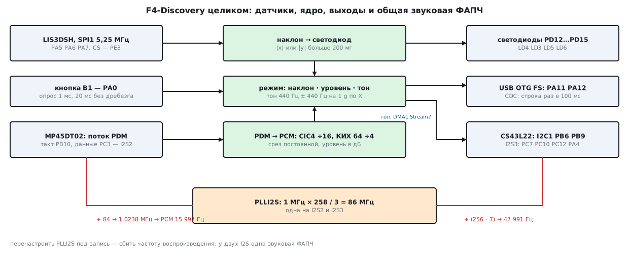
Besides the chip, the STM32F407G-DISC1 board carries a LIS3DSH accelerometer, a CS43L22 audio DAC with an amplifier, an MP45DT02 digital microphone, four LEDs, a button and a USB OTG connector. Usually each part is covered by a separate example. Here they are put together into one device: tilting the board lights an LED, the button switches the mode, the microphone shows the sound level as a bar of LEDs, the CS43L22 plays a tone whose pitch depends on the tilt, and every 100 ms a status line goes out over USB CDC.
The most interesting part inside is the microphone. It does not output samples but a stream of ones and zeros at about 1 MHz (PDM), and the program has to turn it into sound: the F407 has no DFSDM block like the L4 has (section 18б). The second place where it is easy to go wrong is the clocks: the two I2S interfaces share one audio PLL.
Checked without a board. The core of the device (disco_core.c) does not touch hardware:
the experiment sim_disco.c was built with gcc on the PC and with arm-none-eabi-gcc for Cortex-M4,
and run in qemu-system-arm -M netduinoplus2 (output via semihosting,
section 35а) — the PC and QEMU output matched line for line. The microphone in the experiment is
a model of a second-order sigma-delta modulator, not the MP45DT02 itself. A model
in Python (disco_host.py) repeats the core bit for bit (the CRC-32 of
all samples matched) and uses these samples to compute the signal-to-noise ratio and the
frequency response. The firmware disco_f407.c was built with armclang against the
F4 pack headers without warnings; it has not been run on a board.
References: the STM32F4-Discovery BSP and the lis3dsh, cs43l22 drivers from the
STM32CubeF4 1.28.0 archive — pins, registers and the setup order; the
UM1472 manual and the board schematics are not on the disk, so the wiring follows the BSP, and the
LQFP100 package pin numbers follow the pinout table of the DS8626 datasheet; RM0090 —
the I2S formulas and table 127 of frequencies, the RCC_PLLI2SCFGR register (7.3.23),
SPI_I2SCFGR (28.5.8), table 42 of DMA1 requests. I2S — section 18а,
USB CDC — sections 20 and 198б, FIR filters — 81а, board pins —
appendix E.3. Check — _verify/disco198l_check.py.
Terms used in the documentation
Term Meaning PDM, pulse density modulation one bit per clock cycle sigma-delta modulator how the microphone produces its bit stream CIC filter, integrator, comb a chain of integrators and combs with no multiplications decimation factor how many times the sample rate is reduced droop the fall of the frequency response near the band edge aliasing spectrum folding DC blocker removes the constant component dBFS decibels relative to full scale PLLI2S, I2SDIV, ODD, MCKOE the audio PLL, the I2S divider, the odd bit, the MCK output WHO_AM_I the sensor's ID register
198л.1 What the device does and what it is made of
| Function | How |
|---|---|
| tilt | LIS3DSH over SPI1 (5.25 MHz), ±2g, 100 samples per second |
| LEDs | PD12…PD15: tilt above 200 mg on the larger axis — the LED on that side |
| button | PA0, polled every 1 ms, 20 ms without change — a press; three modes in a cycle |
| microphone | MP45DT02 over I2S2: clock 1.0238 MHz, 4th-order CIC ÷16, 64-tap FIR ÷4 — 15997 samples per second |
| level | mean square over 256 samples → whole dB; bar: −50, −40, −30, −20 dB |
| sound | CS43L22: commands over I2C1, samples over I2S3 via DMA1 Stream7 — 47991 Hz, tone 440 Hz ± 440 Hz per 1 g |
| link to the PC | USB OTG FS, CDC class: a 61-byte line every 100 ms |
The wiring comes from the BSP headers (stm32f4_discovery.h,
stm32f4_discovery_audio.h, usbd_conf.c of the demo), the pin numbers
from the DS8626 pinout table (LQFP100 column):
| Block | Signal | Pin | Package pin | Peripheral |
|---|---|---|---|---|
| LEDs | LD4 green, LD3 orange, LD5 red, LD6 blue | PD12, PD13, PD14, PD15 | 59, 60, 61, 62 | GPIO |
| button B1 | pressed — high level | PA0 | 23 | GPIO |
| LIS3DSH | SCK, MISO, MOSI | PA5, PA6, PA7 | 30, 31, 32 | SPI1, AF5 |
| LIS3DSH | CS, INT1, INT2 | PE3, PE0, PE1 | 2, 97, 98 | GPIO |
| CS43L22 | SCL, SDA | PB6, PB9 | 92, 96 | I2C1, AF4 |
| CS43L22 | reset | PD4 | 85 | GPIO |
| CS43L22 | MCK, CK, SD, WS | PC7, PC10, PC12, PA4 | 64, 78, 80, 29 | I2S3, AF6 |
| MP45DT02 | clock, data | PB10, PC3 | 47, 18 | I2S2, AF5 |
| USB OTG FS | VBUS, ID, D−, D+ | PA9, PA10, PA11, PA12 | 68, 69, 70, 71 | AF10 |
| USB, host mode | VBUS power enable | PC0 | 15 | GPIO |
All of this takes SPI1, I2C1, SPI2 and SPI3 (as I2S) and two DMA1 streams — the rest stay free for your own tasks.
198л.2 Clocks: one audio PLL for two I2S
The I2S clock comes from PLLI2S: 1 MHz input (HSE 8 MHz / PLLM = 8), multiplied
by PLLI2SN, divided by PLLI2SR, then the divider inside the I2S
(I2SDIV, ODD). According to RM0090 (7.3.23) the VCO is 100 to 432 MHz,
PLLI2SR is 2 to 7, and the I2S clock is at most 192 MHz. With the MCK output
the sample rate is I2SCLK / (256 · (2 · I2SDIV + ODD)),
without MCK and with a 16-bit frame — I2SCLK / (32 · (2 · I2SDIV + ODD)).
The BSP keeps a PLLI2SN/PLLI2SR table for the output, while the divider is computed
by the HAL (stm32f4xx_hal_i2s.c) with rounding. The same calculation in the model:
| Mode | N / R | I2SCLK |
Divider | Rate | Error |
|---|---|---|---|---|---|
| output 48 kHz | 258 / 3 | 86 MHz | 2·3 + 1 | 47991.071 Hz | −0.0186 % |
| output 44.1 kHz | 271 / 6 | 45.17 MHz | 2·2 + 0 | 44108.073 Hz | +0.0183 % |
| output 16 kHz | 213 / 4 | 53.25 MHz | 2·6 + 1 | 16000.601 Hz | +0.0038 % |
| recording 16 kHz (BSP) | 192 / 6 | 32 MHz | 2·15 + 1 | PCM 16129.03 Hz | +0.806 % |
The first three rows give the same rates as table 127 of RM0090, and a full search over the dividers with a 1 MHz input finds nothing better: 0.0186 % for 48 kHz and 0.0183 % for 44.1 kHz. Recording in the BSP runs with an error of almost one percent: the HAL rounds the divider 31.25 down to 31.
The key point: there is only one PLL. BSP_AUDIO_OUT_ClockConfig sets 258/3,
BSP_AUDIO_IN_ClockConfig sets 192/6. Whoever configures it last wins:
if you enable recording after starting the 48 kHz output, the I2S3 dividers
stay as set for 86 MHz, and the rate becomes 32 MHz / (256 · 7) =
17857.1 Hz. So in this device the PLL has one setting for both I2S: 86 MHz,
the output gets 47991 Hz, and the microphone gets I2SDIV = 42 without MCK:
SPI2->I2SPR = MIC_ODD << SPI_I2SPR_ODD_Pos | MIC_DIV;
The microphone clock is 86 / 84 = 1.0238 MHz, after decimation by 64 that is
15997 samples per second, with the same −0.0186 % error as the output. For
the 44.1 kHz family (271/6) a divider of 44 would give 16039.3 Hz (+0.2456 %).
The firmware checks all these numbers at build time with _Static_assert:
168 MHz for the core, exactly 48 MHz for USB, the VCO and PLLI2SR within the RM0090 limits,
47991 Hz and 1023809 Hz.
198л.3 Accelerometer and LEDs
The LIS3DSH sits on SPI1: divider 16 from 84 MHz — 5.25 MHz, mode 0, chip
select on PE3 driven by hand. The setup is the same as in the BSP: the ID register WHO_AM_I
(register 0x0F) must return 0x3F, CTRL_REG4 (0x20) gets 0x67 —
100 samples per second, axes X, Y, Z, and CTRL_REG5 (0x24) gets 0: ±2g.
The board BSP also understands another sensor, the LIS302DL: it answers 0x3B, and its X
and Y axes are swapped. The sensitivity at ±2g is 0.06 mg per LSB
(LIS3DSH_SENSITIVITY_0_06G), so 1 g is about 16667 LSB.
The LEDs follow the rule of the ST example (mems.c): take the axis with
the larger tilt, and if it exceeds 200 mg, light the LED on that side:
X above 200 — LD5 red, below −200 — LD4 green; Y below −200 —
LD6 blue, above 200 — LD3 orange. 200 mg is a tilt of 11.54°:
| Angle | Sample | mg | Lit on X | Lit on Y |
|---|---|---|---|---|
| −45° | −11786 | −707 | LD4 | LD6 |
| −12° | −3466 | −207 | LD4 | LD6 |
| −11° | −3181 | −190 | none | none |
| 11° | 3179 | 190 | none | none |
| 12° | 3464 | 207 | LD5 | LD3 |
| 45° | 11785 | 707 | LD5 | LD3 |
A sample is two bytes, low and high, one read per byte, as in the BSP:
static void lis_read(int16_t xyz[3])
{
    for (unsigned a = 0; a < 3u; a++) {                               /* по одному байту, как BSP */
        uint8_t lo = lis_rw((uint8_t)(0x80u | (0x28u + 2u * a)), 0);
        uint8_t hi = lis_rw((uint8_t)(0x80u | (0x29u + 2u * a)), 0);
        xyz[a] = lis_mg(lo, hi);                                      /* байты без знака: не как в lis3dsh.c */
    }
}
A bug in the BSP driver. LIS3DSH_ReadACC in lis3dsh.c stores the bytes
in int8_t and adds (high << 8) + low. A low byte of 0x80
and above becomes negative, and −256 LSB is added to the sample,
that is −15.36 mg. The experiment went through all 65536 codes: exactly
half of them are wrong, 32768.
| Sample | Bytes | Correct, mg | BSP, mg |
|---|---|---|---|
| 127 | 7F 00 | 7 | 7 |
| 128 | 80 00 | 7 | −7 |
| 384 | 80 01 | 23 | 7 |
| −100 | 9C FF | −6 | −21 |
| −16667 | E5 BE | −1000 | −1015 |
For a 200 mg threshold this is a trifle; for measurements it is a 15 mg step that comes and goes. Assemble the bytes as unsigned.
198л.4 Button and modes
On the Discovery the button is pulled to ground by a resistor on the board, and a press reads as 1 (appendix E.3). The button is polled from SysTick once per millisecond; a press is a transition to 1 that holds for 20 polls in a row. The experiment: a press with 3 ms of bounce, held for 80 ms, a release with bounce, then noise — 1 ms spikes. There are 7 edges on the input and one press — at millisecond 73, 20 ms after the bounce ends.
Three modes in a cycle:
- 0 — tilt on the LEDs;
- 1 — the microphone level as a bar: −50, −40, −30, −20 dB — one, two, three, four LEDs;
- 2 — a tone in the headphones: exactly 440 Hz, ±440 Hz per 1 g along the X axis, within 220…880 Hz (at 250 mg — 550 Hz), the LEDs show the tilt again.
198л.5 Microphone: from a bit stream to sound
A PDM microphone outputs one bit per clock: the more ones in a row, the higher the pressure. The useful sound is in the low-frequency part of the stream; the modulator pushes the quantization noise upwards. The task is a low-pass filter and decimation by 64. This is done in two steps.
4th-order CIC, ÷16. Four integrators at the bit rate and four combs at a rate 16 times lower, without a single multiplication. One 16-bit I2S word is exactly one CIC sample, 64 kHz. The gain is 16⁴ = 65536, so the integrators overflow — and this is not a bug: in modulo 2³² arithmetic the combs cancel the overflow as long as the result fits in the word width.
    for (int k = 15; k >= 0; k--) {                                   /* I2S отдаёт старший бит первым */
        i0 += (word >> k & 1u) ? 1u : (uint32_t)-1;
        i1 += i0;
        i2 += i1;
        i3 += i2;
    }
64-tap FIR, ÷4. A Kaiser window (beta = 7), cutoff 8 kHz at a rate of
64 kHz, Q15 coefficients that sum to exactly 32768 — DC passes
without loss. Only every fourth output is computed: 64 multiplications per
sample, 1024000 multiplications per second; the CIC takes 4096000 additions per
second. After the FIR comes a DC blocker y += x − x₁ − y/256: its cutoff
frequency is 9.95 Hz.
The experiment: a microphone model at 1024000 bits per second, 0.256 s per tone, a DC offset of 2 % of full scale. The signal-to-noise ratio is taken over the second half of the recording, in the band up to 8 kHz:
| 1 kHz tone, fraction of full scale | CIC + FIR | "count the ones" |
|---|---|---|
| 0.25 | 67.1 dB | 21.9 dB |
| 0.5 | 71.5 dB | 27.5 dB |
| 0.8 | 70.7 dB | — |
| 0.9 | 64.8 dB | — |
| 0.95 | 52.3 dB | — |
"Counting the ones" in 64 bits is a first-order CIC: as simple as it gets and 44 dB worse. Above 0.8 of full scale the noise grows — it is the second-order modulator that overloads, not the filter. Silence at the input gives exactly 0 at the output, a level of −88 dB — the meter cannot resolve anything lower.
Frequency response, tone at 0.5 of full scale; above 8 kHz the tone after decimation lands in the band at a different frequency:
| Tone | Heard as | Run | Model |
|---|---|---|---|
| 100 Hz | 100 Hz | −0.03 dB | −0.03 dB |
| 3 kHz | 3 kHz | −0.10 dB | −0.11 dB |
| 5 kHz | 5 kHz | −0.33 dB | −0.33 dB |
| 6 kHz | 6 kHz | −0.51 dB | −0.52 dB |
| 7 kHz | 7 kHz | −1.76 dB | −1.77 dB |
| 7.5 kHz | 7.5 kHz | −3.63 dB | −3.65 dB |
| 9 kHz | 7 kHz | −19.52 dB | −19.54 dB |
| 12 kHz | 4 kHz | −83.09 dB | −82.79 dB |
| 20 kHz | 4 kHz | −80.63 dB | −80.39 dB |
| 30 kHz | 2 kHz | −97.90 dB | −96.96 dB |
The band is flat up to 6 kHz (−0.5 dB). The weak spot is 8…10 kHz: at 8 kHz the model's response drops by only 6.9 dB, and a 9 kHz tone arrives at 7 kHz attenuated by only 19.5 dB. If you need a clean band up to 8 kHz, use a longer FIR or a higher output rate.
The ST library. The Cube archive has a ready-made PDM2PCM
(libPDMFilter_CM4_GCC_wc16_soft.a). Comparing it with our filter on
the same stream in QEMU did not work out: PDM_Filter_Init reads two addresses from
the Cortex-M4 debug area: 0xE0002000 — the FP_CTRL register of the FPB block
(the core's hardware breakpoints) and 0xE0042000 — DBGMCU_IDCODE
(the chip ID, a register added by ST). netduinoplus2 models neither of them,
and the function does not return within 15 s. This ties
the library to ST chips; on top of that, the BSP enables the CRC clock
for it ("Enable CRC peripheral to unlock the PDM library").
198л.6 Sound on the CS43L22 and a line over USB
The CS43L22 is controlled over I2C1 at 100 kHz (CCR = 210 at 42 MHz),
address 0x94, reset on PD4. The order of writes is taken from cs43l22_Init and
cs43l22_Play of the BSP for headphones: 17 writes, from POWER_CTL1 = 0x01
(off) to POWER_CTL1 = 0x9E (on), volume 70 of 100, which the BSP
formula turns into 0xCB. The format is I2S Philips, 16 bits (INTERFACE_CTL1 = 0x04,
CODEC_STANDARD in the BSP).
The samples go over I2S3 with the MCK output: I2SDIV = 3, ODD = 1, 47991 Hz.
DMA1 Stream7, channel 0 — the SPI3_TX request per table 42 of RM0090 (the microphone uses
Stream3, channel 0, SPI2_RX). The buffer is two halves of 48 stereo frames
(1 ms): while one is playing, the interrupt fills the other with the tone or with zeros.
The tone is a 1024-point sine table with linear interpolation and
a 32-bit phase accumulator: for 440 Hz the step is 39370533. The step
is computed from 48000, but there are actually 47991.07 frames — the tone comes out
at 439.918 Hz, off by the same −0.0186 %.
Every 100 ms the core builds a line and passes it to CDC_Transmit_FS —
the USB stack and the CDC class are the same as in sections 20.7 and 198б:
t=12300 mode=2 x=250 y=-30 z=968 led=4 mic=-23dB tone=550Hz
61 bytes including \r\n ten times a second is 610 bytes/s, far below
the CDC ceiling. armclang 6.24 built disco_f407.c and disco_core.c without
warnings: 1834 and 1112 bytes of code, 2690 bytes of core tables (sine,
FIR, level thresholds), 1117 bytes of RAM.
198л.7 Pitfalls
Two settings for one PLLI2S. The BSP output and recording each set the PLL their own way (258/3 and 192/6), and the second breaks the first: 48 kHz turns into 17857 Hz. Use one PLL frequency for both I2S and dividers that fit it.
Signed accelerometer bytes. As in lis3dsh.c: half of the codes
are shifted by −15.36 mg. Assemble the sample from uint8_t.
Not checking WHO_AM_I. The board BSP is ready for two sensors: the LIS3DSH
(0x3F) and the LIS302DL (0x3B) with different registers and swapped axes —
and tells them apart only by this register.
"Counting the ones" instead of a filter. As simple as it gets, but 27.5 dB instead of 71.5: the quantization noise that the modulator pushed upwards folds back into the band.
A short FIR — aliasing near the edge. 64 taps let 9 kHz through as 7 kHz attenuated by 19.5 dB. The band up to 6 kHz is clean; above that, do the math.
Bit order. I2S outputs the most significant bit first (RM0090): the first PDM bit in time is bit 15 of the word. Getting this wrong reverses every 16 bits in time.
Changing the I2S mode while I2SE is set. The SPI_I2SCFGR fields are changed while
the I2S is disabled (RM0090, 28.5.8): configure first, then I2SE.
Loud sound at the microphone. The second-order modulator overloads at 0.95 of full scale: 52.3 dB instead of 71.5, while the meter shows only −1 dB. Keep the signal at or below 0.8 of full scale (−2 dB on the meter).
The PDM2PCM library in an emulator. It hangs in PDM_Filter_Init: it checks
the chip. Compare against it only on a board.
198л.8 Summary
- One PLLI2S 1 MHz × 258 / 3 = 86 MHz: output 47991 Hz (−0.0186 %), microphone clock 1.0238 MHz, PCM 15997 Hz; recording with the BSP settings (192/6) gives 16129 Hz (+0.806 %) and knocks the output down to 17857 Hz.
- Tilt: 0.06 mg per LSB, the 200 mg threshold = 11.54°; the BSP driver is off by −15.36 mg in 32768 codes out of 65536.
- Button: 7 edges with bounce and noise — one press, 20 ms later.
- PDM → PCM: 4th-order CIC ÷16 and 64-tap FIR ÷4 — 71.5 dB on a tone at 0.5 of full scale versus 27.5 dB for counting the ones; the band is flat up to 6 kHz (−0.51 dB), 12…30 kHz is suppressed by 80…98 dB, 9 kHz by only 19.5.
- The Python model matched the C core in all 16 microphone experiments, and the run matched the frequency-response model to hundredths of a decibel in the band.
- CS43L22: 17 writes over I2C1, a 440 Hz tone via I2S3 and DMA1 Stream7; a 61-byte line over USB CDC every 100 ms.
- armclang: 1834 + 1112 bytes of code, 2690 bytes of tables, 1117 bytes of RAM.
Full source code
disco_f407.c — the whole F4-Discovery firmware: accelerometer, button, microphone, sound and a line over USB.
/* Раздел 198л: всё, что есть на STM32F407G-DISC1, в одной прошивке.
 * LIS3DSH по SPI1 → наклон на светодиоды PD12…PD15; кнопка PA0 меняет режим; микрофон MP45DT02 по I2S2 (PDM) →
 * ядро disco_core (CIC + КИХ) → уровень в дБ; CS43L22: управление по I2C1, звук по I2S3 (48 кГц) — тон, высота
 * от наклона; раз в 100 мс строка состояния в USB CDC (CDC_Transmit_FS из стека USB, раздел 20.7 и 198б).
 * Такты: HSE 8 МГц, SYSCLK 168 МГц, APB1 42 МГц, APB2 84 МГц; одна PLLI2S на оба I2S — 86 МГц.
 * Выводы и настройки периферии — по BSP STM32F4-Discovery из STM32CubeF4 1.28.0; регистры — RM0090. */
#include "stm32f4xx.h"
#include "disco_core.h"

#define HSE_HZ      8000000u
#define PLL_M       8u
#define PLL_N       336u
#define PLL_P       2u
#define PLL_Q       7u
#define SYSCLK_HZ   (HSE_HZ / PLL_M * PLL_N / PLL_P)
#define USB_HZ      (HSE_HZ / PLL_M * PLL_N / PLL_Q)
#define PCLK1_HZ    (SYSCLK_HZ / 4u)
#define PCLK2_HZ    (SYSCLK_HZ / 2u)
#define I2S_N       258u                /* как у BSP для 48 кГц и в табл. 127 RM0090 */
#define I2S_R       3u
#define I2SCLK_HZ   (HSE_HZ / PLL_M * I2S_N / I2S_R)
#define OUT_DIV     3u                  /* I2S3: MCK включён, 16 бит → fs = I2SCLK / (256 · (2·3 + 1)) */
#define OUT_ODD     1u
#define FS_OUT_HZ   (I2SCLK_HZ / (256u * (2u * OUT_DIV + OUT_ODD)))
#define MIC_DIV     42u                 /* I2S2: MCK выключен → CK = I2SCLK / (2·42) — такт микрофона */
#define MIC_ODD     0u
#define MIC_CK_HZ   (I2SCLK_HZ / (2u * MIC_DIV + MIC_ODD))
#define SPI1_DIV    16u                 /* как SPI_BAUDRATEPRESCALER_16 в BSP */
#define I2C_HZ      100000u             /* BSP_I2C_SPEED */
#define CODEC_ADDR  0x94u               /* AUDIO_I2C_ADDRESS */
#define MIC_HALF    64u                 /* слов I2S на половину буфера: 64 · 16 бит = 1 мс, 16 отсчётов PCM */
#define OUT_HALF    48u                 /* стереокадров на половину: 1 мс при 48 кГц */

_Static_assert(SYSCLK_HZ == 168000000u && USB_HZ == 48000000u, "168 МГц ядру и ровно 48 МГц USB (раздел 6, E.3)");
_Static_assert(HSE_HZ / PLL_M * PLL_N >= 100000000u && HSE_HZ / PLL_M * PLL_N <= 432000000u, "RM0090: ГУН PLL 100…432 МГц");
_Static_assert(I2S_N >= 50u && I2S_N <= 432u && HSE_HZ / PLL_M * I2S_N >= 100000000u && HSE_HZ / PLL_M * I2S_N <= 432000000u,
               "RM0090 7.3.23: PLLI2SN 50…432, ГУН 100…432 МГц");
_Static_assert(I2S_R >= 2u && I2S_R <= 7u && I2SCLK_HZ <= 192000000u, "RM0090 7.3.23: PLLI2SR 2…7, I2S не выше 192 МГц");
_Static_assert(FS_OUT_HZ == 47991u, "48 кГц выходят как 47 991 Гц: ошибка −0,0186 %, как в табл. 127");
_Static_assert(MIC_CK_HZ == 1023809u && MIC_CK_HZ / 64u == 15997u, "такт микрофона 1,0238 МГц, PCM 15 997 Гц");
_Static_assert(OUT_DIV >= 2u && MIC_DIV >= 2u && MIC_DIV <= 255u, "RM0090: I2SDIV 2…255");
_Static_assert(PCLK2_HZ / SPI1_DIV == 5250000u, "SPI1 к LIS3DSH — 5,25 МГц");
_Static_assert(PCLK1_HZ / (2u * I2C_HZ) == 210u, "I2C1: CCR = 210 для 100 кГц при 42 МГц");
_Static_assert(SPI_I2SCFGR_I2SCFG_Pos == 8u && SPI_I2SCFGR_I2SSTD_Pos == 4u && SPI_I2SCFGR_CKPOL_Pos == 3u
               && SPI_I2SPR_ODD_Pos == 8u && SPI_I2SPR_MCKOE_Pos == 9u, "поля SPI_I2SCFGR и SPI_I2SPR как в RM0090");
_Static_assert(RCC_PLLI2SCFGR_PLLI2SN_Pos == 6u && RCC_PLLI2SCFGR_PLLI2SR_Pos == 28u, "поля RCC_PLLI2SCFGR как в RM0090");

extern uint8_t CDC_Transmit_FS(uint8_t *buf, uint16_t len);          /* класс CDC из стека USB ST (раздел 20.7) */

static uint16_t mic_buf[2 * MIC_HALF];
static int16_t out_buf[2 * 2 * OUT_HALF];
static int16_t pcm[MIC_HALF / FIR_DEC];
static pdm_t pdm;
static lvl_t lvl = {.db = -96};
static tone_t tone;
static btn_t btn;
static volatile unsigned mode;          /* 0 — наклон, 1 — уровень звука, 2 — тон по наклону */
static volatile uint32_t ms;
static int16_t acc[3];
static char line[96];

static void pin_mode(GPIO_TypeDef *g, unsigned pin, unsigned mode_, unsigned af)
{
    g->MODER = (g->MODER & ~(3u << 2u * pin)) | mode_ << 2u * pin;
    g->OSPEEDR |= 2u << 2u * pin;
    g->AFR[pin >> 3] = (g->AFR[pin >> 3] & ~(15u << 4u * (pin & 7u))) | af << 4u * (pin & 7u);
}

static void clock_init(void)
{
    RCC->CR |= RCC_CR_HSEON;
    while (!(RCC->CR & RCC_CR_HSERDY)) {
    }
    FLASH->ACR = FLASH_ACR_ICEN | FLASH_ACR_DCEN | FLASH_ACR_PRFTEN | FLASH_ACR_LATENCY_5WS;
    RCC->CFGR = RCC_CFGR_PPRE1_DIV4 | RCC_CFGR_PPRE2_DIV2;
    RCC->PLLCFGR = PLL_M | PLL_N << RCC_PLLCFGR_PLLN_Pos | (PLL_P / 2u - 1u) << RCC_PLLCFGR_PLLP_Pos
                 | RCC_PLLCFGR_PLLSRC_HSE | PLL_Q << RCC_PLLCFGR_PLLQ_Pos;
    RCC->CR |= RCC_CR_PLLON;
    while (!(RCC->CR & RCC_CR_PLLRDY)) {
    }
    RCC->CFGR |= RCC_CFGR_SW_PLL;
    while ((RCC->CFGR & RCC_CFGR_SWS) != RCC_CFGR_SWS_PLL) {
    }
    RCC->PLLI2SCFGR = I2S_N << RCC_PLLI2SCFGR_PLLI2SN_Pos | I2S_R << RCC_PLLI2SCFGR_PLLI2SR_Pos;  /* одна на I2S2 и I2S3 */
    RCC->CR |= RCC_CR_PLLI2SON;
    while (!(RCC->CR & RCC_CR_PLLI2SRDY)) {
    }
}

static uint8_t lis_rw(uint8_t addr, uint8_t val)
{
    uint8_t r = 0;
    GPIOE->BSRR = GPIO_BSRR_BR3;                                      /* CS акселерометра — PE3 */
    for (unsigned i = 0; i < 2u; i++) {
        while (!(SPI1->SR & SPI_SR_TXE)) {
        }
        *(volatile uint8_t *)&SPI1->DR = i ? val : addr;
        while (!(SPI1->SR & SPI_SR_RXNE)) {
        }
        r = *(volatile uint8_t *)&SPI1->DR;
    }
    while (SPI1->SR & SPI_SR_BSY) {
    }
    GPIOE->BSRR = GPIO_BSRR_BS3;
    return r;
}

static void lis_read(int16_t xyz[3])
{
    for (unsigned a = 0; a < 3u; a++) {                               /* по одному байту, как BSP */
        uint8_t lo = lis_rw((uint8_t)(0x80u | (0x28u + 2u * a)), 0);
        uint8_t hi = lis_rw((uint8_t)(0x80u | (0x29u + 2u * a)), 0);
        xyz[a] = lis_mg(lo, hi);                                      /* байты без знака: не как в lis3dsh.c */
    }
}

static int i2c_write(uint8_t reg, uint8_t val)
{
    uint32_t t = 100000u;
    I2C1->CR1 |= I2C_CR1_START;
    while (!(I2C1->SR1 & I2C_SR1_SB))
        if (!--t)
            return -1;
    I2C1->DR = CODEC_ADDR;
    while (!(I2C1->SR1 & (I2C_SR1_ADDR | I2C_SR1_AF)))
        if (!--t)
            return -1;
    if (I2C1->SR1 & I2C_SR1_AF) {
        I2C1->SR1 &= ~I2C_SR1_AF;
        I2C1->CR1 |= I2C_CR1_STOP;
        return -1;
    }
    (void)I2C1->SR2;
    I2C1->DR = reg;
    while (!(I2C1->SR1 & I2C_SR1_TXE))
        if (!--t)
            return -1;
    I2C1->DR = val;
    while (!(I2C1->SR1 & I2C_SR1_BTF))
        if (!--t)
            return -1;
    I2C1->CR1 |= I2C_CR1_STOP;
    return 0;
}

/* Порядок записей — как у cs43l22_Init (наушники, громкость 70 → 0xCB) и cs43l22_Play в BSP. */
static const uint8_t CODEC_SEQ[][2] = {
    {0x02, 0x01}, {0x04, 0xAF}, {0x05, 0x81}, {0x06, 0x04}, {0x20, 0xCB}, {0x21, 0xCB}, {0x0A, 0x00}, {0x0E, 0x04},
    {0x27, 0x00}, {0x1F, 0x0F}, {0x1A, 0x0A}, {0x1B, 0x0A}, {0x0E, 0x06}, {0x22, 0x00}, {0x23, 0x00}, {0x04, 0xAF},
    {0x02, 0x9E}};

static int codec_init(void)
{
    int err = 0;
    GPIOD->BSRR = GPIO_BSRR_BS4;                                      /* PD4 — снять сброс CS43L22 */
    for (unsigned i = 0; i < sizeof CODEC_SEQ / sizeof CODEC_SEQ[0]; i++)
        err |= i2c_write(CODEC_SEQ[i][0], CODEC_SEQ[i][1]);
    return err;
}

static void dma_ring(DMA_Stream_TypeDef *s, volatile uint32_t *periph, void *mem, uint32_t n, uint32_t dir)
{
    s->CR = 0;
    while (s->CR & DMA_SxCR_EN) {
    }
    s->PAR = (uint32_t)periph;
    s->M0AR = (uint32_t)mem;
    s->NDTR = n;
    s->CR = (0u << DMA_SxCR_CHSEL_Pos) | dir | DMA_SxCR_MINC | DMA_SxCR_CIRC | DMA_SxCR_MSIZE_0 | DMA_SxCR_PSIZE_0
          | DMA_SxCR_PL_1 | DMA_SxCR_HTIE | DMA_SxCR_TCIE;
    s->CR |= DMA_SxCR_EN;
}

void disco_start(void)
{
    clock_init();
    RCC->AHB1ENR |= RCC_AHB1ENR_GPIOAEN | RCC_AHB1ENR_GPIOBEN | RCC_AHB1ENR_GPIOCEN | RCC_AHB1ENR_GPIODEN
                  | RCC_AHB1ENR_GPIOEEN | RCC_AHB1ENR_DMA1EN;
    RCC->APB1ENR |= RCC_APB1ENR_I2C1EN | RCC_APB1ENR_SPI2EN | RCC_APB1ENR_SPI3EN;
    RCC->APB2ENR |= RCC_APB2ENR_SPI1EN;
    for (unsigned p = 12; p <= 15u; p++)
        pin_mode(GPIOD, p, 1u, 0);                                    /* светодиоды */
    pin_mode(GPIOD, 4, 1u, 0);                                        /* сброс кодека */
    pin_mode(GPIOE, 3, 1u, 0);                                        /* CS LIS3DSH */
    GPIOE->BSRR = GPIO_BSRR_BS3;
    for (unsigned p = 5; p <= 7u; p++)
        pin_mode(GPIOA, p, 2u, 5u);                                   /* SPI1: PA5 SCK, PA6 MISO, PA7 MOSI */
    pin_mode(GPIOB, 6, 2u, 4u);                                       /* I2C1: PB6 SCL, PB9 SDA */
    pin_mode(GPIOB, 9, 2u, 4u);
    GPIOB->OTYPER |= GPIO_OTYPER_OT6 | GPIO_OTYPER_OT9;
    pin_mode(GPIOC, 7, 2u, 6u);                                       /* I2S3: PC7 MCK, PC10 CK, PC12 SD, PA4 WS */
    pin_mode(GPIOC, 10, 2u, 6u);
    pin_mode(GPIOC, 12, 2u, 6u);
    pin_mode(GPIOA, 4, 2u, 6u);
    pin_mode(GPIOB, 10, 2u, 5u);                                      /* I2S2: PB10 CK микрофона, PC3 данные */
    pin_mode(GPIOC, 3, 2u, 5u);
    /* PA0 — вход без подтяжки: на плате своя подтяжка вниз, нажатие — 1 (приложение E.3) */

    SPI1->CR1 = SPI_CR1_MSTR | SPI_CR1_SSM | SPI_CR1_SSI | (3u << SPI_CR1_BR_Pos) | SPI_CR1_SPE;  /* /16, режим 0 */
    int ok_acc = lis_rw(0x80u | 0x0Fu, 0) == 0x3Fu;                   /* WHO_AM_I = 0x3F у LIS3DSH */
    if (ok_acc) {
        lis_rw(0x20u, 0x67u);                                         /* CTRL_REG4: 100 Гц, оси X, Y, Z */
        lis_rw(0x24u, 0x00u);                                         /* CTRL_REG5: ±2g, полоса 800 Гц */
    }

    I2C1->CR2 = PCLK1_HZ / 1000000u;
    I2C1->CCR = PCLK1_HZ / (2u * I2C_HZ);
    I2C1->TRISE = PCLK1_HZ / 1000000u + 1u;
    I2C1->CR1 = I2C_CR1_PE;
    int ok_codec = codec_init() == 0;

    tone_set(&tone, 440u, 48000u, 8192);
    dma_ring(DMA1_Stream7, &SPI3->DR, out_buf, 2u * 2u * OUT_HALF, DMA_SxCR_DIR_0);   /* SPI3_TX: поток 7, канал 0 */
    SPI3->CR2 = SPI_CR2_TXDMAEN;
    SPI3->I2SPR = SPI_I2SPR_MCKOE | OUT_ODD << SPI_I2SPR_ODD_Pos | OUT_DIV;
    SPI3->I2SCFGR = SPI_I2SCFGR_I2SMOD | 2u << SPI_I2SCFGR_I2SCFG_Pos;          /* ведущий, передача, Philips, 16 бит */
    SPI3->I2SCFGR |= SPI_I2SCFGR_I2SE;                                /* включать — после настройки (RM0090, 28.5.8) */

    dma_ring(DMA1_Stream3, &SPI2->DR, mic_buf, 2u * MIC_HALF, 0);    /* SPI2_RX: поток 3, канал 0 */
    SPI2->CR2 = SPI_CR2_RXDMAEN;
    SPI2->I2SPR = MIC_ODD << SPI_I2SPR_ODD_Pos | MIC_DIV;
    SPI2->I2SCFGR = SPI_I2SCFGR_I2SMOD | 3u << SPI_I2SCFGR_I2SCFG_Pos | 2u << SPI_I2SCFGR_I2SSTD_Pos
                  | SPI_I2SCFGR_CKPOL;                                /* ведущий, приём, LSB, CPOL = 1 — как BSP */
    SPI2->I2SCFGR |= SPI_I2SCFGR_I2SE;

    NVIC_SetPriority(DMA1_Stream3_IRQn, 2);
    NVIC_SetPriority(DMA1_Stream7_IRQn, 1);
    NVIC_EnableIRQ(DMA1_Stream3_IRQn);
    NVIC_EnableIRQ(DMA1_Stream7_IRQn);
    SysTick_Config(SYSCLK_HZ / 1000u);
    GPIOD->BSRR = (ok_acc && ok_codec) ? 0u : GPIO_BSRR_BS14;         /* красный — что-то не ответило */
}

/* Микрофон: готова половина — 64 слова PDM → 16 отсчётов PCM → уровень. */
void DMA1_Stream3_IRQHandler(void)
{
    uint32_t isr = DMA1->LISR;
    DMA1->LIFCR = DMA_LIFCR_CHTIF3 | DMA_LIFCR_CTCIF3;
    const uint16_t *half = (isr & DMA_LISR_TCIF3) ? mic_buf + MIC_HALF : mic_buf;
    size_t n = pdm_feed(&pdm, half, MIC_HALF, pcm);
    lvl_feed(&lvl, pcm, n);
}

/* Выход: пока DMA играет одну половину, вторую заполняем тоном или тишиной. */
void DMA1_Stream7_IRQHandler(void)
{
    uint32_t isr = DMA1->HISR;
    DMA1->HIFCR = DMA_HIFCR_CHTIF7 | DMA_HIFCR_CTCIF7;
    int16_t *half = (isr & DMA_HISR_TCIF7) ? out_buf + 2u * OUT_HALF : out_buf;
    if (mode == 2u)
        tone_fill(&tone, half, OUT_HALF);
    else
        for (unsigned i = 0; i < 2u * OUT_HALF; i++)
            half[i] = 0;
}

void SysTick_Handler(void)
{
    ms++;
    if (btn_tick(&btn, (int)(GPIOA->IDR & GPIO_IDR_ID0)))
        mode = (mode + 1u) % 3u;
}

void disco_loop(void)
{
    uint32_t last = 0;
    for (;;) {
        __WFI();
        if (ms - last < 10u)
            continue;
        last = ms;
        lis_read(acc);                                                /* 100 раз в секунду, как ODR датчика */
        uint32_t hz = tone_hz_from_tilt(acc[0]);
        tone_set(&tone, hz, 48000u, 8192);
        uint8_t leds = mode == 1u ? lvl_leds(lvl.db) : tilt_leds(acc[0], acc[1]);
        GPIOD->BSRR = (uint32_t)leds << 12 | (uint32_t)(~leds & 0xFu) << (12 + 16);
        if (last % 100u == 0u) {
            size_t n = app_line(line, sizeof line, last, mode, acc[0], acc[1], acc[2], leds, lvl.db, mode == 2u ? hz : 0u);
            CDC_Transmit_FS((uint8_t *)line, (uint16_t)n);
        }
    }
}
Next: section 198м "Mini-project: weather station — sensors, log and display".