 Embedded HandbookApps
99д. MPU-6050 gyroscope-accelerometer over I2C: registers, FIFO, interrupt and offset calibration
In section 99 the MPU-6050 was woken up, read as fourteen bytes a hundred times a second, and the angle was assembled by a complementary filter. In 99а the same class of sensors runs over SPI at 8 kHz in Betaflight, in 99б the gyroscope, accelerometer and magnetometer are fused into an orientation by the Madgwick filter. Here — the chip driver itself: how to find it on the bus, wake it up and not put it back to sleep, how two registers set the sample rate, what the built-in filter gives, why a FIFO and how it breaks on overflow, how to read on the data-ready interrupt through DMA, and how to remove the gyroscope zero offset — in software or by writing into its own registers.
Sources: RM0008 (DocID13902 Rev 17): receiving three or more bytes as
master, method 2, p. 763; one and two bytes — p. 764; reception through
DMA with the LAST bit, p. 769; the LAST and DMAEN bits in
I2C_CR2, p. 775; table 78 — I2C1_RX on DMA1 channel 7, p. 281; fast
mode — pp. 783–784; AFIO_EXTICR2, p. 190; EXTI_RTSR, p. 211; the pin
mode table, p. 160. DocID13587 Rev 17 (STM32F103x8/xB): PB6 —
I2C1_SCL, PB7 — I2C1_SDA, both FT, PB5 not FT, p. 32. The project
has no MPU-6050 datasheet or register map. Register numbers, bits and
delays follow open-source drivers: Betaflight 2026.12.0-alpha (commit
744f95f, accgyro_mpu.h, accgyro_mpu.c, accgyro_mpu6050.c,
accgyro_spi_mpu6000.c, GPL-3.0), Zephyr 4.4.2 (mpu6050.h,
mpu6050.c, Apache-2.0), VESC (commit 4fd8279, mpu9150.h — the
MPU-9150 is an MPU-6050 and a magnetometer in one package, GPL-3.0) and
Klipper (commit 7bc4d09, mpu9250.py, sensor_mpu9250.c, GPL-3.0). The
FIFO size of 1024 bytes, the order of values in a FIFO frame, what
happens on overflow, the unit of the XG_OFFS_USR registers and the
shape of the built-in filter are common knowledge, not verified: the
model repeats them rather than checks them. All numbers come from
running the driver _verify/imu99f/mpu99f.c, built by
arm-none-eabi-gcc 12.2.1 for the Cortex-M3 and run in QEMU 7.2 (the
mps2-an385 machine), with our own MPU-6050 model in Python 3.11; the
firmware is built by armclang 6.24. The gyroscope offset, noise and
board motion are assumptions: the numbers below describe the model, not
the sensor.
What it is called in the documentation
Original Meaning WHO_AM_I"who am I" register: the model code PWR_MGMT_1,SLEEP,DEVICE_RESET,CLKSELpower management: sleep, full reset, clock source SIGNAL_PATH_RESETreset of the measurement paths DLPF_CFG(digital low pass filter)built-in digital low-pass filter SMPLRT_DIV(sample rate divider)sample rate divider gyroscope output rate the rate at which the gyroscope produces samples internally FS_SEL,AFS_SEL(full scale)gyroscope and accelerometer range FIFO_EN,USER_CTRL,FIFO_COUNT,FIFO_R_Wwhat goes into the FIFO, its enable and reset, byte counter, read window FIFO_OFLOWFIFO overflowed DATA_RDY,INT_PIN_CFG,LATCH_INT_ENdata ready, INT pin setup, latch XG_OFFS_USRuser gyroscope offset for X bias, zero-rate offset zero offset
99д.1 Address, model code, sleep and the gyroscope clock
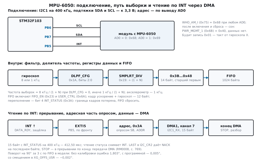
A module with the MPU-6050 is connected like this:
| Module pin | STM32F103 | Purpose |
|---|---|---|
| VCC | 3.3 V | supply |
| GND | GND | ground |
| SCL | PB6 | I2C1 clock |
| SDA | PB7 | I2C1 data |
| INT | PB5 | "data ready"; EXTI5 on the rising edge |
| AD0 | GND or 3.3 V | address 0x68 or 0x69 |
The AD0 pin sets the address: at ground — 0x68, at the supply — 0x69
(MPU9150_ADDRESS_AD0_LOW and _HIGH in VESC). The code in WHO_AM_I
(0x75) does not depend on AD0: Betaflight, when given address 0x69,
still expects 0x68. Modules with similar chips answer differently:
MPU-6500 — 0x70, MPU-9250 — 0x71 (so in Betaflight and Zephyr). Betaflight
has separate drivers for them, and Zephyr has its own temperature formula
for the MPU-6500; the driver of this section targets only the MPU-6050
and rejects them:
/* кто на шине: 0x68 (AD0 = 0) или 0x69 (AD0 = 1); WHO_AM_I у MPU-6050 — 0x68 при любом AD0 */
int mpu_probe(mpu_t *d)
{
    static const uint8_t addr[2] = {MPU_ADDR_AD0_LO, MPU_ADDR_AD0_HI};
    uint8_t who;
    d->who = 0;
    for (int i = 0; i < 2; i++) {
        d->addr = addr[i];
        if (xfer_done(d, mpu_port_xfer(d->addr, 0, 0, 0, 0)) != MPU_OK)
            continue;                                           /* нет ответа на этот адрес */
        if (mpu_read_regs(d, MPU_WHO_AM_I, &who, 1) != MPU_OK)
            return MPU_E_BUS;
        d->who = who;
        return who == MPU_WHO_6050 ? MPU_OK : MPU_E_ID;         /* 0x70 — MPU-6500, 0x71 — MPU-9250: другие карты */
    }
    return MPU_E_NACK;
}
In the model, identification on a board with AD0 at ground takes 2
exchanges, with AD0 at the supply — 3: first a NACK at 0x68. A board
with code 0x70 gives MPU_E_ID, −3; an empty bus — MPU_E_NACK, −1.
Sleep. After power-on the MPU-6050 sleeps: PWR_MGMT_1 (0x6B) has
bit 6, SLEEP, set (MPU6050_SLEEP_EN in Zephyr; 0x40 is the value of
SET_PWR_MGMT_1_SLEEP in Klipper). In the model the register reads 0x40
after power-on, the fourteen data bytes are zeros, and waiting for data
ready ends after 395 ms with MPU_E_TIMEOUT, −4.
Reset. Bit 7 of the same register, DEVICE_RESET, returns all
registers to their initial values, and SIGNAL_PATH_RESET (0x68), bits
2, 1 and 0, resets the gyroscope, accelerometer and thermometer paths.
After each one Betaflight waits 100 ms, citing the documentation:
/* полный сброс: все регистры — по умолчанию, и микросхема снова спит */
int mpu_reset(mpu_t *d)
{
    int rc;
    if ((rc = mpu_write_reg(d, MPU_PWR_MGMT_1, MPU_PWR1_RESET)) != MPU_OK)
        return rc;
    mpu_port_delay_us(MPU_RESET_MS * 1000u);
    if ((rc = mpu_write_reg(d, MPU_SIGNAL_PATH_RST, MPU_SPR_ALL)) != MPU_OK)
        return rc;
    mpu_port_delay_us(MPU_RESET_MS * 1000u);
    return MPU_OK;
}
In the model the reset is the writes 6B 80 and 68 07 and 200 ms.
After it PWR_MGMT_1 is 0x40 again: the chip sleeps again. A reset after
setup erases both the setup and the wake-up — data disappear, and
waiting again ends with −4 after 395 ms.
Clock. Waking up means writing zero into bit 6 of PWR_MGMT_1. At
the same time the clock source CLKSEL (bits 2:0) is chosen: 1 — the
oscillator referenced to gyroscope X, 3 — to gyroscope Z
(MPU_CLK_SEL_PLLGYROX and _PLLGYROZ in Betaflight; Betaflight itself
writes 0x03 for the MPU-6050). The oscillator needs time after CLKSEL
changes — "max 10ms" in a Betaflight comment:
/* разбудить с тактом от гироскопа X, частота, фильтр, диапазоны, INT по готовности данных (держится до чтения статуса) */
int mpu_init(mpu_t *d, uint8_t dlpf, uint8_t div, uint8_t fs, uint8_t afs)
{
    uint8_t v;
    int rc;
    if (dlpf > 6u || fs > 3u || afs > 3u)
        return MPU_E_ARG;
    if ((rc = mpu_write_reg(d, MPU_PWR_MGMT_1, MPU_CLK_PLL_XGYRO)) != MPU_OK)    /* SLEEP = 0 */
        return rc;
    mpu_port_delay_us(MPU_PLL_MS * 1000u);
    if ((rc = mpu_read_regs(d, MPU_PWR_MGMT_1, &v, 1)) != MPU_OK)
        return rc;
    if (v & MPU_PWR1_SLEEP)
        return MPU_E_SLEEP;                                     /* запись не дошла: микросхема спит и даёт нули */
    const uint8_t cfg[][2] = {{MPU_SMPLRT_DIV, div}, {MPU_CONFIG, dlpf}, {MPU_GYRO_CONFIG, (uint8_t)(fs << 3)},
                              {MPU_ACCEL_CONFIG, (uint8_t)(afs << 3)}, {MPU_INT_PIN_CFG, MPU_INTCFG_LATCH},
                              {MPU_INT_ENABLE, MPU_INT_DATA_RDY}};
    for (uint32_t i = 0; i < sizeof cfg / sizeof cfg[0]; i++)
        if ((rc = mpu_write_reg(d, cfg[i][0], cfg[i][1])) != MPU_OK)
            return rc;
    d->dlpf = dlpf;
    d->div = div;
    d->fs = fs;
    d->afs = afs;
    return MPU_OK;
}
The driver reads PWR_MGMT_1 back: if the sleep bit stayed, the write
did not get through, and it returns MPU_E_SLEEP rather than silent
zeros. In the model, setup for 200 samples per second is the writes
6B 01, 19 04, 1A 03, 1B 00, 1C 00, 37 20, 38 01, the read
6B → 01, 11 ms together with waiting for the oscillator.
99д.2 Sample rate: DLPF_CFG and SMPLRT_DIV
Two registers decide how often the data are updated. CONFIG (0x1A),
bits 2:0 — DLPF_CFG, the built-in filter. The names of its codes in
Betaflight give the bandwidth: 0 — 256 Hz, 1 — 188, 2 — 98, 3 — 42, 4 —
20, 5 — 10, 6 — 5 Hz, 7 — 2100HZ_NOLPF, no filter. The filter decides
the rate at which the gyroscope produces samples internally: with
DLPF_CFG = 0 — 8 kHz (MPU6050_SMPLRT_DIV 0 // 8000Hz in Betaflight),
with the filter — 1 kHz ("Gyroscope Output Rate = 1kHz when the DLPF is
enabled"). SMPLRT_DIV (0x19) divides it: sample rate = gyroscope rate
/ (1 + SMPLRT_DIV).
/* частота выборок в тысячных герца: гироскоп — 8 кГц без фильтра (DLPF_CFG = 0), 1 кГц с ним; делится на 1 + SMPLRT_DIV */
uint32_t mpu_rate_mhz(uint8_t dlpf, uint8_t div)
{
    const uint32_t base = (dlpf == 0u || dlpf == 7u) ? 8000000u : 1000000u;
    return base / (1u + div);
}
The driver does not accept code 7: what it gives on the MPU-6050 cannot be checked against the documents on disk. The model counts samples by the time they appear, the driver — by the formula:
| DLPF_CFG | SMPLRT_DIV | Driver, Hz | Model, Hz |
|---|---|---|---|
| 0 | 0 | 8000 | 8000.00 |
| 0 | 7 | 1000 | 1000.00 |
| 0 | 79 | 100 | 100.00 |
| 1 | 0 | 1000 | 1000.00 |
| 3 | 4 | 200 | 200.00 |
| 3 | 9 | 100 | 100.00 |
| 6 | 99 | 10 | 10.00 |
The accelerometer is updated 1000 times a second ("Accel Sample Rate 1kHz" in Betaflight). At 8 kHz it lags behind the gyroscope: in the model, across 32 FIFO frames in a row the acceleration changes every 8.
The filter is needed not only against noise. Samples are taken less often than the gyroscope sees vibration, and everything above half the sample rate folds into low frequencies. In the model the board shakes at 205 Hz with ±20 °/s about X, 100 samples per second; 205 Hz folds into 5 Hz — a slow rocking that does not exist. The built-in filter in the model is a first-order stage with the bandwidth from the code name (its real shape is not verified), RMS at the output over 100 samples with 14.14 °/s at the input:
| DLPF_CFG | Bandwidth | SMPLRT_DIV | RMS, °/s | Peak, °/s |
|---|---|---|---|---|
| 0 | 256 Hz | 79 | 11.05 | 15.70 |
| 1 | 188 Hz | 9 | 10.20 | 14.51 |
| 3 | 42 Hz | 9 | 3.05 | 4.35 |
| 5 | 10 Hz | 9 | 0.74 | 1.09 |
With code 0 (256 Hz bandwidth, 8 kHz, divider 79) almost all the vibration passes into the samples. A 42 Hz bandwidth gives 3.05 °/s, 10 Hz — 0.74. The filter bandwidth must be below half the sample rate; the price is delay.
99д.3 Ranges, LSB value, temperature and the 14-byte burst
The ranges are GYRO_CONFIG (0x1B) and ACCEL_CONFIG (0x1C), bits 4:3;
the tables are in 99.2. The driver converts to integers: thousandths of
°/s through the same table 1310, 655, 328, 164 (codes per °/s times 10)
as in Zephyr, thousandths of g — by dividing by 16384 >> AFS_SEL:
| ±250 °/s | ±500 °/s | ±1000 °/s | ±2000 °/s | |
|---|---|---|---|---|
| 1 LSB | 8 thousandths of °/s | 15 | 30 | 61 |
| 100 °/s about X, code | 13101 | 6550 | 3280 | 1640 |
| 300 °/s about Z, code → °/s | 32767 → 250.13 | 19653 → 300.05 | 9842 → 300.06 | 4921 → 300.06 |
In the model the board rotates at 300 °/s about Z: at ±250 °/s the code hits 32767, and the driver sees 250.13 °/s. The accelerometer LSB at ±2 g is 0.061 mg: in integer thousandths of g code 1 gives 0, which does not matter for tilt; for vibration a smaller unit is used.
Temperature. Code / 340 + 36.53 °C — so in Betaflight
(tempScale = 1.0f / 340.0f, tempZero = 36.53f) and in 99.3:
/* температура кристалла: код / 340 + 36,53 °C */
int32_t mpu_temp_cdeg(int32_t raw)
{
    return (int32_t)rdiv((int64_t)raw * 100, 340) + 3653;
}
Zephyr 4.4.2 adds 36, not 36.53: with the die at 30.00 °C the model gives code −2220, the driver gives 30.00 °C, the Zephyr formula — 29.47 °C. The 0.53 °C difference is a constant offset; this is the die temperature, not the air (99.8).
Burst. Acceleration X, Y, Z, temperature and gyroscope X, Y, Z lie in a row from 0x3B to 0x48, each value high byte first. They must be read in one burst: register number 0x3B, repeated start, 14 bytes.
/* 14 байт с 0x3B: ускорение X, Y, Z, температура, гироскоп X, Y, Z */
void mpu_parse14(const uint8_t b[14], mpu_raw_t *r)
{
    for (int k = 0; k < 3; k++) {
        r->a[k] = mpu_be16(b + 2 * k);
        r->g[k] = mpu_be16(b + 8 + 2 * k);
    }
    r->t = mpu_be16(b + 6);
}
In the model the board rotates at 10, −20 and 30 °/s; the burst is
00 3D FF F2 3F F3 F7 54 05 2E F5 CB 0F 69: acceleration 61, −14, 16371, temperature −2220, gyroscope 1326, −2613, 3945 — that is 10.12, −19.95, 30.11 °/s.
Bus time: polling INT_STATUS — 39 SCL clocks, 14 bytes — 156. Poll
and data together take 487.50 µs at 400 kHz and 1950.00 at 100 kHz. If the
read starts right at INT_STATUS (0x3A) and takes 15 bytes — 165
clocks, 412.50 µs at 400 kHz and 1650.00 at 100 kHz: with one sample per
read the bus passes at most 2424 samples per second at 400 kHz and
606 at 100 kHz. Faster — only through the FIFO.
99д.4 FIFO: enabling, counter, overflow and recovery
The FIFO accumulates samples inside the chip, and they can be read in
bursts, less often than the sample rate. What goes in — FIFO_EN
(0x23): bit 7 — temperature, 6, 5, 4 — gyroscope X, Y, Z, 3 —
acceleration (VESC). Bit 6 of USER_CTRL (0x6A) enables the FIFO, bit
2 resets it. The start order is as in Klipper: stop writing, reset,
enable, read INT_STATUS to clear the overflow flag, start writing:
/* остановить запись, сбросить FIFO, включить его, снять флаг переполнения чтением статуса, пустить запись */
int mpu_fifo_start(mpu_t *d, uint8_t mask)
{
    uint8_t st;
    int rc;
    d->fifo_mask = mask;
    d->frame = frame_bytes(mask);
    if (!d->frame)
        return MPU_E_ARG;
    if ((rc = mpu_write_reg(d, MPU_FIFO_EN, 0u)) != MPU_OK || (rc = mpu_write_reg(d, MPU_USER_CTRL, MPU_USER_FIFO_RST)) != MPU_OK
        || (rc = mpu_write_reg(d, MPU_USER_CTRL, MPU_USER_FIFO_EN)) != MPU_OK || (rc = mpu_read_regs(d, MPU_INT_STATUS, &st, 1)) != MPU_OK)
        return rc;
    return mpu_write_reg(d, MPU_FIFO_EN, mask);
}
The byte counter is FIFO_COUNTH and FIFO_COUNTL (0x72, 0x73); from
the high byte Klipper takes five bits (& 0x1f). The bytes themselves
are read from FIFO_R_W (0x74) in a burst: the register pointer stays
on it, and each byte of the burst is the next one from the FIFO.
An acceleration + gyroscope frame is 12 bytes: in the model the values go in increasing register order, as in the burst from 0x3B, but without the temperature. At 1 kHz after 50 ms the FIFO holds 600 bytes. The 1024-byte FIFO overflows after 85.62 ms, and 1024 is not divisible by 12 — remainder 4. The model discards the oldest bytes, and the FIFO start ends up in the middle of a frame. Whoever reads frames without looking at the flag gets this: acceleration −122, 74, −43, gyroscope 18, 16348, 245. Acceleration Z, about 16384, moved into gyroscope Y.
There are two signs of overflow: bit 4 of INT_STATUS, FIFO_OFLOW
(Klipper checks the same, FIFO_OVERFLOW_INT 0x10), and a counter not
divisible by the frame. The driver checks both and recovers in one way —
by a reset:
/* до max кадров из FIFO. Переполнение или счёт не кратен кадру — граница кадров потеряна: сброс FIFO и ошибка */
int mpu_fifo_read(mpu_t *d, mpu_raw_t *out, uint32_t max, uint32_t *got)
{
    uint8_t st, b[MPU_FIFO_CHUNK * 14u];
    uint16_t cnt;
    uint32_t n;
    int rc;
    *got = 0;
    if ((rc = mpu_read_regs(d, MPU_INT_STATUS, &st, 1)) != MPU_OK || (rc = mpu_fifo_count(d, &cnt)) != MPU_OK)
        return rc;
    if ((st & MPU_INT_FIFO_OFLOW) || cnt % d->frame) {
        d->overflows++;
        d->lost += cnt / d->frame;                              /* то, что лежало, уже со сдвигом — выбросить */
        if ((rc = mpu_fifo_start(d, d->fifo_mask)) != MPU_OK)
            return rc;
        return (st & MPU_INT_FIFO_OFLOW) ? MPU_E_OFLOW : MPU_E_ALIGN;
    }
    n = cnt / d->frame;
    if (n > max)
        n = max;
    while (*got < n) {
        uint32_t k = n - *got > MPU_FIFO_CHUNK ? MPU_FIFO_CHUNK : n - *got;
        if ((rc = mpu_read_regs(d, MPU_FIFO_R_W, b, k * d->frame)) != MPU_OK)
            return rc;
        for (uint32_t i = 0; i < k; i++)
            mpu_fifo_parse(d->fifo_mask, b + i * d->frame, &out[*got + i]);
        *got += k;
    }
    return MPU_OK;
}
In the model after the overflow mpu_fifo_read returned MPU_E_OFLOW,
−6, and reset the FIFO; 5 ms later — 5 frames, the first one is
acceleration 77, −13, 16389, gyroscope 240, −114, 78: in place again. 84 frames were discarded — what
lay in the FIFO shifted. A gyroscope-only frame is 6 bytes, and the FIFO
at 1 kHz overflows twice as late, after 170.74 ms.
Does the bus keep up. At 1 kHz the driver reads 12-byte frames 8 at a time: 894 SCL clocks, that is 1117.50 µs per frame at 100 kHz — more than the millisecond in which the next one arrives. Over 3000 frames the FIFO overflowed 5 times, 425 frames were discarded. At 400 kHz — 279.38 µs per frame and not a single overflow. A 6-byte frame — 462 clocks, 577.50 µs at 100 kHz: here standard mode is enough.
99д.5 Data-ready interrupt and reading through DMA
Polling INT_STATUS occupies the bus for nothing. The INT pin reports
readiness itself: INT_ENABLE (0x38) = 0x01, DATA_RDY_EN. Zeros in
bits 7 and 6 of INT_PIN_CFG mean a push-pull output, active high
(INTMODE_ACTIVEHIGH and INTDRV_PUSHPULL in VESC, INT_LEVEL_HIGH,
INT_OPEN_DIS in a Betaflight comment), and without the latch INT is a
50 µs pulse (MPU9150_INTLATCH_50USPULSE). With LATCH_INT_EN (bit 5 of
INT_PIN_CFG, 0x37) INT holds until INT_STATUS is read
(INTCLEAR_STATUSREAD). The driver sets the latch and starts reading at
0x3A: 15 bytes — status and data, and this same read releases INT. In
the model the status in such a burst is 0x01, and the next read of 0x3A
gives 0x00.
On the F103 INT goes to PB5: input with pull-down (code 1000 in the pin
mode table, p. 160, ODR = 0), AFIO_EXTICR2, bits 7:4 = 0001 — port B
(p. 190), the rising edge is enabled by EXTI_RTSR (p. 211). The I2C1
receiver is served by DMA1 channel 7 (table 78, p. 281). Per RM0008
(p. 769), in master reception the DMA signals the end at the last but
one byte, the LAST bit in I2C_CR2 (p. 775) makes I2C answer NACK
after the last one, and STOP is set in the transfer-complete
interrupt. DMAEN may also be set during the ADDR event, before it is
cleared:
/* INT: регистр 0x3A, повторный старт, адрес чтения — опросом; 15 байт — DMA с LAST: NACK на последнем (с. 769) */
void EXTI9_5_IRQHandler(void)
{
static const uint8_t reg = MPU_INT_STATUS;
EXTI->PR = 1u << 5;
if (busy) {
missed++; /* прошлое чтение не кончилось */
return;
}
DMA1_Channel7->CNDTR = sizeof dma_buf;
DMA1_Channel7->CCR = DMA_CCR7_MINC | DMA_CCR7_TCIE | DMA_CCR7_PL_1 | DMA_CCR7_EN; /* из периферии в память */
if (addr_phase(dev.addr, ®, 1, 1, 0) != MPU_OK) {
DMA1_Channel7->CCR = 0;
(void)fail(MPU_E_BUS);
bus_errors++;
return;
}
I2C1->CR2 |= I2C_CR2_DMAEN | I2C_CR2_LAST; /* в событии ADDR, до его снятия (с. 769) */
busy = 1;
(void)I2C1->SR2; /* ADDR снят: дальше байты идут сами */
}
/* конец DMA: STOP, разбор, поправка смещения, курс по гироскопу Z */
void DMA1_Channel7_IRQHandler(void)
{
    mpu_raw_t r;
    DMA1->IFCR = DMA_IFCR_CTCIF7;
    DMA1_Channel7->CCR = 0;
    I2C1->CR1 |= I2C_CR1_STOP;
    I2C1->CR2 &= (uint16_t)~(I2C_CR2_DMAEN | I2C_CR2_LAST);
    mpu_parse14(dma_buf + 1, &r);
    for (int k = 0; k < 3; k++) {
        gyro_mdps[k] = mpu_gyro_corr_mdps(&dev, r.g[k], k);
        acc_mg[k] = mpu_acc_mg(r.a[k], dev.afs);
    }
    temp_cdeg = mpu_temp_cdeg(r.t);
    int64_t y = yaw_udeg;
    mpu_angle_step(&y, gyro_mdps[2], DT_US);
    yaw_udeg = y;
    samples++;
    busy = 0;
}
The address phase — start, address, register number, repeated start,
read address — is about 29 SCL clocks, 72.5 µs at 400 kHz, and the
interrupt waits for it by polling. The remaining 15 bytes — 337.5 µs —
go without the CPU. At 200 samples per second that is 82.5 ms of every
second on the bus. Interrupts and DMA were not run in the model: the
firmware fw99f.c is only built by armclang, the handlers are not
tested on hardware.
The latch has a trap. If INT went up and the read did not happen — for
example, the interrupt was enabled while INT was already high — there
will be no more edges: INT waits for a read, the read waits for an edge.
After enabling EXTI the firmware looks at PB5 and, if it reads one,
starts the first read itself (EXTI_SWIER).
99д.6 Gyroscope offset calibration
The zero offset is what the gyroscope shows at rest. In the model it is
1.80, −0.90 and 0.60 °/s, the noise is 0.05 °/s. The driver averages n
samples and also looks at the spread: if on any axis it exceeds 1 °/s
(131 codes at ±250 °/s), the device was moved, and the result is
MPU_E_MOVED, −8. The offset is kept in codes × 16 so as not to lose
fractions of an LSB when subtracting.
| Samples, 1 kHz | Time | Error X, Y, Z — thousandths of °/s |
|---|---|---|
| 10 | 9 ms | −2, 17, 15 |
| 100 | 99 ms | 0, 2, −5 |
| 1000 | 999 ms | 0, 1, −1 |
A thousand samples is enough: the remainder is a few thousandths of °/s. A bump of 30 °/s for 50 ms during calibration gave a spread of 3965 codes — refusal. But a slow turn at 2 °/s does not change the spread — 41 with a threshold of 131 — and the Z offset came out 2.60 °/s instead of 0.60: constant rotation cannot be told from offset. Calibrate on a fixed support, not in the hand.
Into the chip registers. Registers 0x13 to 0x18 are XG_OFFS_USR,
YG_OFFS_USR, ZG_OFFS_USR, 16 bits each, high byte first (Betaflight,
MPU_RA_XG_OFFS_USRH). The value is added to the gyroscope output
inside, and there is nothing left to subtract in software. The documents
on disk do not name the unit of these registers; by common knowledge it
is the LSB of the ±1000 °/s range, that is 4 codes at ±250. So the driver
does not take it on trust: it writes, measures again and, if more than
0.1 °/s remains, zeroes the registers and subtracts itself:
/* Смещение гироскопа: среднее в покое. use_hw — записать его в XG_OFFS_USR в предположении «1 код регистра = 4 кода
 * выхода при ±250 °/с» и перемерить: остаток больше 0,1 °/с — единица не та, регистры обнулить и вычитать программно */
int mpu_cal_gyro(mpu_t *d, uint32_t n, int use_hw)
{
    int32_t b[3], s[3], r[3];
    int16_t off[3] = {0, 0, 0};
    int rc;
    d->cal = 0;
    for (int k = 0; k < 3; k++)
        d->bias_q4[k] = 0;
    if ((rc = mpu_set_gyro_offs(d, off)) != MPU_OK || (rc = mpu_gyro_bias(d, n, b, s)) != MPU_OK)
        return rc;
    for (int k = 0; k < 3; k++)
        d->bias_q4[k] = b[k];
    d->cal = MPU_CAL_SW;
    if (!use_hw)
        return MPU_CAL_SW;
    for (int k = 0; k < 3; k++)
        off[k] = (int16_t)-rdiv((int64_t)b[k] * (1 << d->fs), 64);
    if ((rc = mpu_set_gyro_offs(d, off)) != MPU_OK || (rc = mpu_gyro_bias(d, n, r, s)) != MPU_OK)
        return rc;
    for (int k = 0; k < 3; k++) {
        if (r[k] > 16 * mdps_to_raw(MPU_HW_RESID_MDPS, d->fs) || r[k] < -16 * mdps_to_raw(MPU_HW_RESID_MDPS, d->fs)) {
            off[0] = off[1] = off[2] = 0;
            rc = mpu_set_gyro_offs(d, off);                     /* регистр понят не так — вычитаем сами */
            return rc != MPU_OK ? rc : MPU_CAL_SW;
        }
    }
    for (int k = 0; k < 3; k++)
        d->bias_q4[k] = r[k];                                   /* остаток доберём программно */
    d->cal = MPU_CAL_HW;
    return MPU_CAL_HW;
}
| Register model | Range | Result | Written | Remainder, thousandths of °/s |
|---|---|---|---|---|
| 4 codes | ±250 °/s | MPU_CAL_HW |
−59, 29, −20 | 1, −14, −8 |
| 2 codes | ±250 °/s | MPU_CAL_SW |
0, 0, 0 | 1800, −897, 603 |
| 4 codes | ±2000 °/s | MPU_CAL_HW |
−59, 30, −20 | 0, 15, −11 |
| 2 codes | ±2000 °/s | MPU_CAL_SW |
0, 0, 0 | 1799, −899, 598 |
In the "4 codes" model the driver wrote −59, 29, −20 — that is −offset × 131 / 4 —
and the remainder is at most 15 thousandths of °/s. At ±2000 °/s almost
the same number is written: the register unit does not depend on the
range. In the "2 codes" model the remainder after the write is half the
offset, the driver noticed it, returned MPU_CAL_SW and subtracts in
software.
Checking with a turn. The board is turned by 90° about Z in one second (speed is a raised cosine, up to 180.00 °/s), 200 samples per second, acceleration + gyroscope frames from the FIFO, the angle is the sum of speed × 5 ms:
| Calibration | Frames | Z angle | Error | X angle (should be 0) |
|---|---|---|---|---|
| none | 600 | 91.803° | 1.803° | 5.397° |
| in software | 600 | 90.005° | 0.005° | 0.002° |
in XG_OFFS_USR |
600 | 89.998° | −0.002° | −0.004° |
| in software, 600 ms pause | 600 | 27.867° | −62.133° | −0.002° |
Without calibration 1.8° about Z and 5.4° about X build up over 3 s — offset × time. Software correction and the registers give thousandths of a degree. The last row — the program "stalled" once for 600 ms: the FIFO overflowed, the reset discarded 85 frames, and the turn that fell into the pause was lost — an angle of 27.867° instead of 90.
99д.7 Pitfalls
No answer at 0x68. AD0 is at the supply: address 0x69. The driver tries both — 3 exchanges instead of 2 in the model.
It answers, but the code is 0x70 or 0x71. This is an MPU-6500 or an
MPU-9250, not an MPU-6050. The driver returns MPU_E_ID, −3.
All zeros. The chip sleeps: after power-on and after DEVICE_RESET
PWR_MGMT_1 = 0x40. In the model waiting for data ready ends after
395 ms with −4. Reset only before setup, not after.
Garbage after a pause in FIFO reading. Overflow: 1024 bytes are not
divisible by the frame, and frames shift. Check FIFO_OFLOW and the
counter divisibility, on either — reset the FIFO. Acceleration Z in
gyroscope Y is its sure sign.
The FIFO overflows by itself. The bus does not keep up: at 100 kHz a
12-byte frame costs 1117.50 µs with a period of 1000. Put the bus at 400 kHz
(CCR = F/S | 30, TRISE = 11, 15б.2), shorten the frame, or lower
the rate.
Fails at 400 kHz. The pull-ups are weak: in fast mode the edge is no longer than 300 ns, and with a line capacitance of 400 pF the pull-up must be no more than 885 Ω (17.3). A short bus on a board is tens of picofarads; long wires to the module are a reason to lower the rate. PB6 and PB7 are FT (p. 32), PB5 is not: the INT of a module powered from 3.3 V suits it.
Interrupts stopped coming. INT in the latch waits for an
INT_STATUS read, and the read waits for an edge. Start the read
yourself if INT is already high (99д.5).
The angle drifts after calibration. It was calibrated in the hand or on a rotating table: in the model 2 °/s of rotation became offset. Or the temperature changed — the offset depends on it (99.6).
The rate stops at 250 °/s. The range is too small: code 32767. In the model 300 °/s at ±250 reads as 250.13.
At 8 kHz the acceleration repeats. The accelerometer updates at 1 kHz — eight frames in a row with the same value.
99д.8 Summary
- Address 0x68 or 0x69 by AD0,
WHO_AM_I= 0x68 with either; 0x70 and 0x71 are other chips. - After power-on and reset
PWR_MGMT_1= 0x40, sleep and zeros; writing 0x01 wakes it with the clock from gyroscope X; 10 ms for the oscillator. - Sample rate = 8 kHz (
DLPF_CFG= 0) or 1 kHz / (1 +SMPLRT_DIV): code 3 and divider 4 — 200 Hz. The filter is needed against aliasing too: 205 Hz of vibration at 100 Hz sampling — RMS 11.05 °/s without a filter and 0.74 °/s with a 10 Hz bandwidth (model). - 14 bytes from 0x3B in one burst, high byte first; temperature — code /
340 + 36.53 °C; at 400 kHz 15 bytes from
INT_STATUStake 412.50 µs. - FIFO: a 12-byte frame at 1 kHz overflows 1024 bytes in 85.62 ms; after an overflow the frames shift — only a reset helps.
- At 100 kHz the bus does not keep up with a 12-byte frame at 1 kHz: 5 overflows per 3000 frames; at 400 kHz — none.
- INT with the latch is released by reading
INT_STATUS; 15 bytes go through DMA1 channel 7 withLAST,STOP— at the end of DMA. - The gyroscope offset is the mean of 1000 samples at rest: error in
thousandths of °/s; into
XG_OFFS_USR— with re-measurement. A 90° turn over 3 s: 1.803° without calibration and 0.005° with it.
Full sources
mpu99f.h — registers, bits, error codes, port and driver functions.
/* mpu99f.h — раздел 99д: драйвер MPU-6050 по I2C — регистры, частота выборок, пачка из 14 байт, FIFO, прерывание
 * «данные готовы» и калибровка смещений гироскопа. Регистров микроконтроллера не знает: говорит с микросхемой только
 * через порт mpu_port_*. В прошивке fw99f.c порт — I2C1 STM32F103, в стенде host99f.c — модель model99f.py.
 * Номера регистров и биты — как в accgyro_mpu.h, accgyro_mpu6050.c, accgyro_spi_mpu6000.c (Betaflight), mpu6050.h
 * (Zephyr 4.4.2), mpu9150.h (VESC) и sensor_mpu9250.c / mpu9250.py (Klipper); даташита MPU-6050 в проекте нет. */
#ifndef MPU99F_H
#define MPU99F_H
#include <stdint.h>

/* ── адрес и регистры ─────────────────────────────────────────────────── */
#define MPU_ADDR_AD0_LO     0x68u       /* вывод AD0 на земле */
#define MPU_ADDR_AD0_HI     0x69u       /* AD0 на питании */
#define MPU_XG_OFFS_USRH    0x13u       /* смещения гироскопа X, Y, Z: по два байта, старший первым, 0x13…0x18 */
#define MPU_SMPLRT_DIV      0x19u       /* частота выборок = частота гироскопа / (1 + SMPLRT_DIV) */
#define MPU_CONFIG          0x1Au       /* DLPF_CFG [2:0] */
#define MPU_GYRO_CONFIG     0x1Bu       /* FS_SEL [4:3] */
#define MPU_ACCEL_CONFIG    0x1Cu       /* AFS_SEL [4:3] */
#define MPU_FIFO_EN         0x23u
#define MPU_INT_PIN_CFG     0x37u
#define MPU_INT_ENABLE      0x38u
#define MPU_INT_STATUS      0x3Au
#define MPU_ACCEL_XOUT_H    0x3Bu       /* 14 байт: ускорение X, Y, Z, температура, гироскоп X, Y, Z — старший первым */
#define MPU_SIGNAL_PATH_RST 0x68u
#define MPU_USER_CTRL       0x6Au
#define MPU_PWR_MGMT_1      0x6Bu
#define MPU_FIFO_COUNTH     0x72u       /* счётчик байт в FIFO: 0x72 и 0x73 */
#define MPU_FIFO_R_W        0x74u
#define MPU_WHO_AM_I        0x75u
#define MPU_WHO_6050        0x68u       /* и при адресе 0x69 */
#define MPU_WHO_6500        0x70u
#define MPU_WHO_9250        0x71u

/* ── биты ─────────────────────────────────────────────────────────────── */
#define MPU_PWR1_RESET      0x80u       /* DEVICE_RESET */
#define MPU_PWR1_SLEEP      0x40u
#define MPU_CLK_PLL_XGYRO   0x01u       /* CLKSEL = 1: генератор с опорой на гироскоп X */
#define MPU_SPR_ALL         0x07u       /* сброс тракта: гироскоп, акселерометр, температура */
#define MPU_USER_FIFO_EN    0x40u
#define MPU_USER_FIFO_RST   0x04u
#define MPU_FIFO_TEMP       0x80u
#define MPU_FIFO_XG         0x40u
#define MPU_FIFO_YG         0x20u
#define MPU_FIFO_ZG         0x10u
#define MPU_FIFO_ACCEL      0x08u
#define MPU_INT_DATA_RDY    0x01u       /* бит в INT_ENABLE и INT_STATUS */
#define MPU_INT_FIFO_OFLOW  0x10u
#define MPU_INTCFG_LATCH    0x20u       /* INT держится до чтения INT_STATUS; без него — импульс 50 мкс */

#define MPU_FIFO_SIZE       1024u       /* байт; по общим сведениям, даташита нет — в модели так */
#define MPU_RESET_MS        100u        /* после DEVICE_RESET и сброса тракта — как в Betaflight */
#define MPU_PLL_MS          10u         /* установка генератора после смены CLKSEL — «не больше 10 мс» */
#define MPU_POLL_US         100u        /* опрос INT_STATUS */
#define MPU_POLL_TRIES      2000u       /* 200 мс */
#define MPU_REST_MDPS       1000        /* калибровка: размах больше 1 °/с по любой оси — прибор двигали */
#define MPU_HW_RESID_MDPS   100         /* после записи XG_OFFS_USR остаток не больше 0,1 °/с, иначе — программно */
#define MPU_FIFO_CHUNK      8u          /* кадров FIFO за одно чтение */

enum { MPU_OK = 0, MPU_E_NACK = -1, MPU_E_BUS = -2, MPU_E_ID = -3, MPU_E_TIMEOUT = -4, MPU_E_SLEEP = -5,
       MPU_E_OFLOW = -6, MPU_E_ALIGN = -7, MPU_E_MOVED = -8, MPU_E_ARG = -9 };
enum { MPU_CAL_SW = 1, MPU_CAL_HW = 2 };

typedef struct {
    int16_t a[3], t, g[3];              /* коды как есть: ускорение, температура, угловая скорость */
} mpu_raw_t;

typedef struct {
    uint8_t addr, who, dlpf, div, fs, afs, fifo_mask, cal;
    uint16_t frame;                     /* байт в кадре FIFO */
    int16_t offs[3];                    /* записано в XG_OFFS_USR */
    int32_t bias_q4[3];                 /* программное смещение гироскопа, коды × 16 */
    uint32_t xfers, errors, overflows, lost;
} mpu_t;

/* ── порт ─────────────────────────────────────────────────────────────── */
/* ntx байт записи, затем (если nrx) повторный старт и nrx байт чтения; ntx = nrx = 0 — только адрес.
 * 0, MPU_E_NACK или MPU_E_BUS */
int mpu_port_xfer(uint8_t addr7, const uint8_t *tx, uint32_t ntx, uint8_t *rx, uint32_t nrx);
void mpu_port_delay_us(uint32_t us);

/* ── регистры ─────────────────────────────────────────────────────────── */
int mpu_write_reg(mpu_t *d, uint8_t reg, uint8_t val);
int mpu_read_regs(mpu_t *d, uint8_t reg, uint8_t *buf, uint32_t n);
int mpu_probe(mpu_t *d);
int mpu_reset(mpu_t *d);
int mpu_init(mpu_t *d, uint8_t dlpf, uint8_t div, uint8_t fs, uint8_t afs);
uint32_t mpu_rate_mhz(uint8_t dlpf, uint8_t div);

/* ── данные ───────────────────────────────────────────────────────────── */
int16_t mpu_be16(const uint8_t *b);
void mpu_parse14(const uint8_t b[14], mpu_raw_t *r);
int mpu_wait_drdy(mpu_t *d);
int mpu_read_sample(mpu_t *d, mpu_raw_t *r);
int32_t mpu_gyro_mdps(int32_t raw, uint8_t fs);
int32_t mpu_acc_mg(int32_t raw, uint8_t afs);
int32_t mpu_temp_cdeg(int32_t raw);

/* ── FIFO ─────────────────────────────────────────────────────────────── */
int mpu_fifo_start(mpu_t *d, uint8_t mask);
int mpu_fifo_count(mpu_t *d, uint16_t *n);
void mpu_fifo_parse(uint8_t mask, const uint8_t *b, mpu_raw_t *r);
int mpu_fifo_read(mpu_t *d, mpu_raw_t *out, uint32_t max, uint32_t *got);

/* ── калибровка гироскопа ─────────────────────────────────────────────── */
int mpu_gyro_bias(mpu_t *d, uint32_t n, int32_t bias_q4[3], int32_t spread[3]);
int mpu_set_gyro_offs(mpu_t *d, const int16_t off[3]);
int mpu_cal_gyro(mpu_t *d, uint32_t n, int use_hw);
int32_t mpu_gyro_corr_mdps(const mpu_t *d, int32_t raw, int axis);
void mpu_angle_step(int64_t *ang_udeg, int32_t mdps, uint32_t dt_us);

#endif
mpu99f.c — driver: identification, sleep and reset, setup, sample rate, burst, FIFO, calibration.
/* mpu99f.c — раздел 99д: драйвер MPU-6050. Один и тот же файл собирается в прошивку (armclang, Cortex-M3) и в стенд
* (arm-none-eabi-gcc, Cortex-M3 в QEMU): микроконтроллера он не знает, только порт mpu_port_*.
* Всё целыми: угловая скорость — в тысячных °/с, ускорение — в тысячных g, температура — в сотых °C. */
#include "mpu99f.h"
static const uint16_t gyro_lsb_x10[4] = {1310, 655, 328, 164}; /* кодов на 1 °/с × 10: ±250 … ±2000 °/с */
static int xfer_done(mpu_t *d, int rc)
{
d->xfers++;
if (rc)
d->errors++;
return rc;
}
int mpu_write_reg(mpu_t *d, uint8_t reg, uint8_t val)
{
uint8_t b[2] = {reg, val};
return xfer_done(d, mpu_port_xfer(d->addr, b, 2, 0, 0));
}
/* номер регистра, повторный старт, n байт подряд: указатель регистров в микросхеме идёт сам */
int mpu_read_regs(mpu_t *d, uint8_t reg, uint8_t *buf, uint32_t n)
{
return xfer_done(d, mpu_port_xfer(d->addr, ®, 1, buf, n));
}
static int64_t rdiv(int64_t a, int64_t b) /* b > 0, округление к ближайшему */
{
return a >= 0 ? (a + b / 2) / b : -((-a + b / 2) / b);
}
/* кто на шине: 0x68 (AD0 = 0) или 0x69 (AD0 = 1); WHO_AM_I у MPU-6050 — 0x68 при любом AD0 */
int mpu_probe(mpu_t *d)
{
static const uint8_t addr[2] = {MPU_ADDR_AD0_LO, MPU_ADDR_AD0_HI};
uint8_t who;
d->who = 0;
for (int i = 0; i < 2; i++) {
d->addr = addr[i];
if (xfer_done(d, mpu_port_xfer(d->addr, 0, 0, 0, 0)) != MPU_OK)
continue; /* нет ответа на этот адрес */
if (mpu_read_regs(d, MPU_WHO_AM_I, &who, 1) != MPU_OK)
return MPU_E_BUS;
d->who = who;
return who == MPU_WHO_6050 ? MPU_OK : MPU_E_ID; /* 0x70 — MPU-6500, 0x71 — MPU-9250: другие карты */
}
return MPU_E_NACK;
}
/* полный сброс: все регистры — по умолчанию, и микросхема снова спит */
int mpu_reset(mpu_t *d)
{
int rc;
if ((rc = mpu_write_reg(d, MPU_PWR_MGMT_1, MPU_PWR1_RESET)) != MPU_OK)
return rc;
mpu_port_delay_us(MPU_RESET_MS * 1000u);
if ((rc = mpu_write_reg(d, MPU_SIGNAL_PATH_RST, MPU_SPR_ALL)) != MPU_OK)
return rc;
mpu_port_delay_us(MPU_RESET_MS * 1000u);
return MPU_OK;
}
/* разбудить с тактом от гироскопа X, частота, фильтр, диапазоны, INT по готовности данных (держится до чтения статуса) */
int mpu_init(mpu_t *d, uint8_t dlpf, uint8_t div, uint8_t fs, uint8_t afs)
{
uint8_t v;
int rc;
if (dlpf > 6u || fs > 3u || afs > 3u)
return MPU_E_ARG;
if ((rc = mpu_write_reg(d, MPU_PWR_MGMT_1, MPU_CLK_PLL_XGYRO)) != MPU_OK) /* SLEEP = 0 */
return rc;
mpu_port_delay_us(MPU_PLL_MS * 1000u);
if ((rc = mpu_read_regs(d, MPU_PWR_MGMT_1, &v, 1)) != MPU_OK)
return rc;
if (v & MPU_PWR1_SLEEP)
return MPU_E_SLEEP; /* запись не дошла: микросхема спит и даёт нули */
const uint8_t cfg[][2] = {{MPU_SMPLRT_DIV, div}, {MPU_CONFIG, dlpf}, {MPU_GYRO_CONFIG, (uint8_t)(fs << 3)},
{MPU_ACCEL_CONFIG, (uint8_t)(afs << 3)}, {MPU_INT_PIN_CFG, MPU_INTCFG_LATCH},
{MPU_INT_ENABLE, MPU_INT_DATA_RDY}};
for (uint32_t i = 0; i < sizeof cfg / sizeof cfg[0]; i++)
if ((rc = mpu_write_reg(d, cfg[i][0], cfg[i][1])) != MPU_OK)
return rc;
d->dlpf = dlpf;
d->div = div;
d->fs = fs;
d->afs = afs;
return MPU_OK;
}
/* частота выборок в тысячных герца: гироскоп — 8 кГц без фильтра (DLPF_CFG = 0), 1 кГц с ним; делится на 1 + SMPLRT_DIV */
uint32_t mpu_rate_mhz(uint8_t dlpf, uint8_t div)
{
const uint32_t base = (dlpf == 0u || dlpf == 7u) ? 8000000u : 1000000u;
return base / (1u + div);
}
int16_t mpu_be16(const uint8_t *b)
{
return (int16_t)((uint16_t)b[0] << 8 | b[1]); /* старший байт первым */
}
/* 14 байт с 0x3B: ускорение X, Y, Z, температура, гироскоп X, Y, Z */
void mpu_parse14(const uint8_t b[14], mpu_raw_t *r)
{
for (int k = 0; k < 3; k++) {
r->a[k] = mpu_be16(b + 2 * k);
r->g[k] = mpu_be16(b + 8 + 2 * k);
}
r->t = mpu_be16(b + 6);
}
/* опрос INT_STATUS: чтение снимает флаг и отпускает вывод INT */
int mpu_wait_drdy(mpu_t *d)
{
uint8_t st;
int rc;
for (uint32_t i = 0; i < MPU_POLL_TRIES; i++) {
if ((rc = mpu_read_regs(d, MPU_INT_STATUS, &st, 1)) != MPU_OK)
return rc;
if (st & MPU_INT_DATA_RDY)
return MPU_OK;
mpu_port_delay_us(MPU_POLL_US);
}
return MPU_E_TIMEOUT; /* спит или не настроена */
}
/* одна выборка: дождаться готовности и прочитать 14 байт одной пачкой */
int mpu_read_sample(mpu_t *d, mpu_raw_t *r)
{
uint8_t b[14];
int rc;
if ((rc = mpu_wait_drdy(d)) != MPU_OK)
return rc;
if ((rc = mpu_read_regs(d, MPU_ACCEL_XOUT_H, b, 14)) != MPU_OK)
return rc;
mpu_parse14(b, r);
return MPU_OK;
}
int32_t mpu_gyro_mdps(int32_t raw, uint8_t fs)
{
return (int32_t)rdiv((int64_t)raw * 10000, gyro_lsb_x10[fs & 3u]);
}
int32_t mpu_acc_mg(int32_t raw, uint8_t afs)
{
return (int32_t)rdiv((int64_t)raw * 1000, 16384 >> (afs & 3u)); /* 16384, 8192, 4096, 2048 кодов на g */
}
/* температура кристалла: код / 340 + 36,53 °C */
int32_t mpu_temp_cdeg(int32_t raw)
{
return (int32_t)rdiv((int64_t)raw * 100, 340) + 3653;
}
/* ── FIFO ─────────────────────────────────────────────────────────────── */
static uint16_t frame_bytes(uint8_t mask)
{
return (uint16_t)(((mask & MPU_FIFO_ACCEL) ? 6u : 0u) + ((mask & MPU_FIFO_TEMP) ? 2u : 0u) + ((mask & MPU_FIFO_XG) ? 2u : 0u)
+ ((mask & MPU_FIFO_YG) ? 2u : 0u) + ((mask & MPU_FIFO_ZG) ? 2u : 0u));
}
/* остановить запись, сбросить FIFO, включить его, снять флаг переполнения чтением статуса, пустить запись */
int mpu_fifo_start(mpu_t *d, uint8_t mask)
{
uint8_t st;
int rc;
d->fifo_mask = mask;
d->frame = frame_bytes(mask);
if (!d->frame)
return MPU_E_ARG;
if ((rc = mpu_write_reg(d, MPU_FIFO_EN, 0u)) != MPU_OK || (rc = mpu_write_reg(d, MPU_USER_CTRL, MPU_USER_FIFO_RST)) != MPU_OK
|| (rc = mpu_write_reg(d, MPU_USER_CTRL, MPU_USER_FIFO_EN)) != MPU_OK || (rc = mpu_read_regs(d, MPU_INT_STATUS, &st, 1)) != MPU_OK)
return rc;
return mpu_write_reg(d, MPU_FIFO_EN, mask);
}
int mpu_fifo_count(mpu_t *d, uint16_t *n)
{
uint8_t b[2];
int rc = mpu_read_regs(d, MPU_FIFO_COUNTH, b, 2);
*n = (uint16_t)((b[0] & 0x1Fu) << 8 | b[1]);
return rc;
}
/* кадр FIFO: величины идут по возрастанию номеров регистров — ускорение, температура, гироскоп X, Y, Z */
void mpu_fifo_parse(uint8_t mask, const uint8_t *b, mpu_raw_t *r)
{
uint32_t p = 0;
*r = (mpu_raw_t){{0, 0, 0}, 0, {0, 0, 0}};
if (mask & MPU_FIFO_ACCEL) {
for (int k = 0; k < 3; k++, p += 2)
r->a[k] = mpu_be16(b + p);
}
if (mask & MPU_FIFO_TEMP) {
r->t = mpu_be16(b + p);
p += 2;
}
for (int k = 0; k < 3; k++) {
if (mask & (MPU_FIFO_XG >> k)) {
r->g[k] = mpu_be16(b + p);
p += 2;
}
}
}
/* до max кадров из FIFO. Переполнение или счёт не кратен кадру — граница кадров потеряна: сброс FIFO и ошибка */
int mpu_fifo_read(mpu_t *d, mpu_raw_t *out, uint32_t max, uint32_t *got)
{
uint8_t st, b[MPU_FIFO_CHUNK * 14u];
uint16_t cnt;
uint32_t n;
int rc;
*got = 0;
if ((rc = mpu_read_regs(d, MPU_INT_STATUS, &st, 1)) != MPU_OK || (rc = mpu_fifo_count(d, &cnt)) != MPU_OK)
return rc;
if ((st & MPU_INT_FIFO_OFLOW) || cnt % d->frame) {
d->overflows++;
d->lost += cnt / d->frame; /* то, что лежало, уже со сдвигом — выбросить */
if ((rc = mpu_fifo_start(d, d->fifo_mask)) != MPU_OK)
return rc;
return (st & MPU_INT_FIFO_OFLOW) ? MPU_E_OFLOW : MPU_E_ALIGN;
}
n = cnt / d->frame;
if (n > max)
n = max;
while (*got < n) {
uint32_t k = n - *got > MPU_FIFO_CHUNK ? MPU_FIFO_CHUNK : n - *got;
if ((rc = mpu_read_regs(d, MPU_FIFO_R_W, b, k * d->frame)) != MPU_OK)
return rc;
for (uint32_t i = 0; i < k; i++)
mpu_fifo_parse(d->fifo_mask, b + i * d->frame, &out[*got + i]);
*got += k;
}
return MPU_OK;
}
/* ── калибровка гироскопа ─────────────────────────────────────────────── */
static int32_t mdps_to_raw(int32_t mdps, uint8_t fs)
{
return (int32_t)rdiv((int64_t)mdps * gyro_lsb_x10[fs & 3u], 10000);
}
/* n выборок в покое: среднее (коды × 16) и размах по каждой оси; размах больше 1 °/с — прибор двигали */
int mpu_gyro_bias(mpu_t *d, uint32_t n, int32_t bias_q4[3], int32_t spread[3])
{
int64_t sum[3] = {0, 0, 0};
int32_t lo[3] = {32767, 32767, 32767}, hi[3] = {-32768, -32768, -32768};
mpu_raw_t r;
int rc;
if (!n)
return MPU_E_ARG;
for (uint32_t i = 0; i < n; i++) {
if ((rc = mpu_read_sample(d, &r)) != MPU_OK)
return rc;
for (int k = 0; k < 3; k++) {
sum[k] += r.g[k];
lo[k] = r.g[k] < lo[k] ? r.g[k] : lo[k];
hi[k] = r.g[k] > hi[k] ? r.g[k] : hi[k];
}
}
rc = MPU_OK;
for (int k = 0; k < 3; k++) {
bias_q4[k] = (int32_t)rdiv(sum[k] * 16, (int64_t)n);
spread[k] = hi[k] - lo[k];
if (spread[k] > mdps_to_raw(MPU_REST_MDPS, d->fs))
rc = MPU_E_MOVED;
}
return rc;
}
/* XG_OFFS_USR, YG_OFFS_USR, ZG_OFFS_USR: шесть байт с 0x13, старший первым */
int mpu_set_gyro_offs(mpu_t *d, const int16_t off[3])
{
uint8_t b[7] = {MPU_XG_OFFS_USRH};
for (int k = 0; k < 3; k++) {
b[1 + 2 * k] = (uint8_t)((uint16_t)off[k] >> 8);
b[2 + 2 * k] = (uint8_t)off[k];
d->offs[k] = off[k];
}
return xfer_done(d, mpu_port_xfer(d->addr, b, 7, 0, 0));
}
/* Смещение гироскопа: среднее в покое. use_hw — записать его в XG_OFFS_USR в предположении «1 код регистра = 4 кода
* выхода при ±250 °/с» и перемерить: остаток больше 0,1 °/с — единица не та, регистры обнулить и вычитать программно */
int mpu_cal_gyro(mpu_t *d, uint32_t n, int use_hw)
{
int32_t b[3], s[3], r[3];
int16_t off[3] = {0, 0, 0};
int rc;
d->cal = 0;
for (int k = 0; k < 3; k++)
d->bias_q4[k] = 0;
if ((rc = mpu_set_gyro_offs(d, off)) != MPU_OK || (rc = mpu_gyro_bias(d, n, b, s)) != MPU_OK)
return rc;
for (int k = 0; k < 3; k++)
d->bias_q4[k] = b[k];
d->cal = MPU_CAL_SW;
if (!use_hw)
return MPU_CAL_SW;
for (int k = 0; k < 3; k++)
off[k] = (int16_t)-rdiv((int64_t)b[k] * (1 << d->fs), 64);
if ((rc = mpu_set_gyro_offs(d, off)) != MPU_OK || (rc = mpu_gyro_bias(d, n, r, s)) != MPU_OK)
return rc;
for (int k = 0; k < 3; k++) {
if (r[k] > 16 * mdps_to_raw(MPU_HW_RESID_MDPS, d->fs) || r[k] < -16 * mdps_to_raw(MPU_HW_RESID_MDPS, d->fs)) {
off[0] = off[1] = off[2] = 0;
rc = mpu_set_gyro_offs(d, off); /* регистр понят не так — вычитаем сами */
return rc != MPU_OK ? rc : MPU_CAL_SW;
}
}
for (int k = 0; k < 3; k++)
d->bias_q4[k] = r[k]; /* остаток доберём программно */
d->cal = MPU_CAL_HW;
return MPU_CAL_HW;
}
int32_t mpu_gyro_corr_mdps(const mpu_t *d, int32_t raw, int axis)
{
return (int32_t)rdiv(((int64_t)raw * 16 - d->bias_q4[axis]) * 10000, 16 * (int64_t)gyro_lsb_x10[d->fs & 3u]);
}
/* угол += скорость × время: тысячные °/с × мкс / 1000 = миллионные доли градуса */
void mpu_angle_step(int64_t *ang_udeg, int32_t mdps, uint32_t dt_us)
{
*ang_udeg += rdiv((int64_t)mdps * dt_us, 1000);
}
fw99f.c — F103 firmware: I2C1 at 400 kHz, reception of one, two and N bytes, calibration, INT on EXTI5 and reading through DMA1.
/* fw99f.c — раздел 99д: MPU-6050 на STM32F103 (BluePill), 72 МГц, APB1 = 36 МГц.
* I2C1: PB6 — SCL, PB7 — SDA (открытый сток, 400 кГц). INT микросхемы — на PB5 (EXTI5, по фронту).
* Запуск: кто на шине (0x68 или 0x69), сброс, 200 выборок в секунду с фильтром 42 Гц, ±250 °/с и ±2 g, калибровка
* смещения гироскопа в покое (2 с — не трогать). Дальше по каждому INT: адресная часть опросом (~29 тактов SCL),
* 15 байт с INT_STATUS (0x3A) — через DMA1, канал 7 (I2C1_RX), STOP — в прерывании по концу передачи.
* Через отладчик: gyro_mdps, acc_mg, temp_cdeg, yaw_udeg — курс по гироскопу Z; samples, missed, cal_rc.
* Тактирование до 72 МГц — как в разделе 6. */
#include "stm32f10x.h"
#include "mpu99f.h"
#define CPU_HZ 72000000u
#define APB1_MHZ 36u
#define I2C_TIMEOUT_US 1000u /* байт на 400 кГц — 22,5 мкс */
#define RATE_DIV 4u /* 1 кГц / (1 + 4) = 200 Гц */
#define DT_US 5000u
#define CAL_N 400u /* 2 с при 200 Гц */
static mpu_t dev;
static uint8_t dma_buf[15]; /* INT_STATUS и 14 байт данных */
static volatile uint8_t busy;
volatile uint32_t samples, missed, bus_errors;
volatile int32_t gyro_mdps[3], acc_mg[3], temp_cdeg, cal_rc;
volatile int64_t yaw_udeg;
static int expired(uint32_t t0, uint32_t us)
{
return DWT->CYCCNT - t0 >= us * (CPU_HZ / 1000000u);
}
void mpu_port_delay_us(uint32_t us)
{
uint32_t t0 = DWT->CYCCNT;
while (!expired(t0, us)) {
}
}
static void gpio_i2c1_init(void)
{
RCC->APB2ENR |= RCC_APB2ENR_IOPBEN | RCC_APB2ENR_AFIOEN;
RCC->APB1ENR |= RCC_APB1ENR_I2C1EN;
RCC->AHBENR |= RCC_AHBENR_DMA1EN;
/* PB6, PB7 — альтернативная функция, открытый сток, 50 МГц (1111); PB5 — вход с подтяжкой к земле (1000) */
GPIOB->CRL = (GPIOB->CRL & 0x000FFFFFu) | 0xFF800000u;
GPIOB->BRR = 1u << 5; /* ODR5 = 0: подтяжка вниз — INT активен высоким */
I2C1->CR1 = 0; /* настраивать при PE = 0 */
I2C1->CR2 = APB1_MHZ;
I2C1->CCR = I2C_CCR_FS | 30u; /* DUTY = 0: 36 МГц / (3 × 30) = 400 кГц */
I2C1->TRISE = APB1_MHZ * 300u / 1000u + 1u; /* 300 нс × 36 МГц = 10,8 → 10 + 1 = 11 */
I2C1->CR1 = I2C_CR1_PE;
}
static int sr1_wait(uint16_t mask)
{
uint32_t t0 = DWT->CYCCNT;
while (!(I2C1->SR1 & mask)) {
if (I2C1->SR1 & I2C_SR1_AF)
return MPU_E_NACK;
if (expired(t0, I2C_TIMEOUT_US))
return MPU_E_BUS;
}
return MPU_OK;
}
static int fail(int rc)
{
I2C1->CR1 |= I2C_CR1_STOP;
I2C1->SR1 = (uint16_t)~I2C_SR1_AF; /* AF снимается записью нуля */
I2C1->CR1 = (uint16_t)((I2C1->CR1 & ~I2C_CR1_POS) | I2C_CR1_ACK);
return rc;
}
/* приём n байт ведущим: один — RM0008, с. 764; два — с. 764, бит POS; три и больше — способ 2, с. 763 */
static int rx_n(uint8_t *rx, uint32_t n)
{
int rc;
if (n == 1u) {
I2C1->CR1 &= (uint16_t)~I2C_CR1_ACK; /* NACK — до снятия ADDR */
(void)I2C1->SR2;
I2C1->CR1 |= I2C_CR1_STOP;
if ((rc = sr1_wait(I2C_SR1_RXNE)) != MPU_OK)
return rc;
rx[0] = (uint8_t)I2C1->DR;
} else if (n == 2u) { /* POS и ACK стоят с повторного старта */
(void)I2C1->SR2;
I2C1->CR1 &= (uint16_t)~I2C_CR1_ACK;
if ((rc = sr1_wait(I2C_SR1_BTF)) != MPU_OK) /* оба байта приняты: в DR и в сдвиговом */
return rc;
I2C1->CR1 |= I2C_CR1_STOP;
rx[0] = (uint8_t)I2C1->DR;
rx[1] = (uint8_t)I2C1->DR;
I2C1->CR1 &= (uint16_t)~I2C_CR1_POS;
} else {
(void)I2C1->SR2; /* ADDR снят, ACK = 1 */
for (uint32_t i = 0; i + 3u < n; i++) {
if ((rc = sr1_wait(I2C_SR1_RXNE)) != MPU_OK)
return rc;
rx[i] = (uint8_t)I2C1->DR;
}
if ((rc = sr1_wait(I2C_SR1_BTF)) != MPU_OK) /* N−2 в DR, N−1 в сдвиговом, SCL прижат */
return rc;
I2C1->CR1 &= (uint16_t)~I2C_CR1_ACK;
rx[n - 3u] = (uint8_t)I2C1->DR;
if ((rc = sr1_wait(I2C_SR1_BTF)) != MPU_OK)
return rc;
I2C1->CR1 |= I2C_CR1_STOP;
rx[n - 2u] = (uint8_t)I2C1->DR;
if ((rc = sr1_wait(I2C_SR1_RXNE)) != MPU_OK)
return rc;
rx[n - 1u] = (uint8_t)I2C1->DR;
}
I2C1->CR1 |= I2C_CR1_ACK;
return MPU_OK;
}
/* старт, адрес, байты записи; при rd — повторный старт и адрес чтения (ADDR ещё не снят) */
static int addr_phase(uint8_t addr7, const uint8_t *tx, uint32_t ntx, int rd, int pos)
{
int rc;
uint32_t t0 = DWT->CYCCNT;
while (I2C1->SR2 & I2C_SR2_BUSY) { /* SDA держит ведомый — раздел 17.6 */
if (expired(t0, I2C_TIMEOUT_US))
return MPU_E_BUS;
}
I2C1->CR1 |= I2C_CR1_ACK | I2C_CR1_START;
if ((rc = sr1_wait(I2C_SR1_SB)) != MPU_OK)
return rc;
I2C1->DR = (uint8_t)(addr7 << 1);
if ((rc = sr1_wait(I2C_SR1_ADDR)) != MPU_OK)
return rc;
(void)I2C1->SR2;
for (uint32_t i = 0; i < ntx; i++) {
if ((rc = sr1_wait(I2C_SR1_TXE)) != MPU_OK)
return rc;
I2C1->DR = tx[i];
}
if (ntx && (rc = sr1_wait(I2C_SR1_BTF)) != MPU_OK)
return rc;
if (!rd)
return MPU_OK;
if (pos)
I2C1->CR1 |= I2C_CR1_POS;
I2C1->CR1 |= I2C_CR1_START; /* повторный старт: номер регистра уже передан */
if ((rc = sr1_wait(I2C_SR1_SB)) != MPU_OK)
return rc;
I2C1->DR = (uint8_t)(addr7 << 1 | 1u);
return sr1_wait(I2C_SR1_ADDR);
}
int mpu_port_xfer(uint8_t addr7, const uint8_t *tx, uint32_t ntx, uint8_t *rx, uint32_t nrx)
{
int rc;
if (nrx && !ntx)
return MPU_E_BUS; /* чтение всегда с номера регистра */
if ((rc = addr_phase(addr7, tx, ntx, nrx != 0u, nrx == 2u)) != MPU_OK)
return fail(rc);
if (!nrx) {
I2C1->CR1 |= I2C_CR1_STOP;
return MPU_OK;
}
if ((rc = rx_n(rx, nrx)) != MPU_OK)
return fail(rc);
return MPU_OK;
}
/* ── INT → DMA ────────────────────────────────────────────────────────── */
static void irq_init(void)
{
DMA1_Channel7->CCR = 0; /* настраивать выключенным */
DMA1_Channel7->CPAR = (uint32_t)&I2C1->DR;
DMA1_Channel7->CMAR = (uint32_t)dma_buf;
AFIO->EXTICR[1] = (AFIO->EXTICR[1] & ~0x00F0u) | AFIO_EXTICR2_EXTI5_PB; /* EXTI5 — порт B, с. 190 */
EXTI->RTSR |= 1u << 5; /* по фронту: INT активен высоким, с. 211 */
EXTI->PR = 1u << 5;
EXTI->IMR |= 1u << 5;
NVIC_SetPriority(DMA1_Channel7_IRQn, 1);
NVIC_SetPriority(EXTI9_5_IRQn, 2);
NVIC_EnableIRQ(DMA1_Channel7_IRQn);
NVIC_EnableIRQ(EXTI9_5_IRQn);
}
/* INT: регистр 0x3A, повторный старт, адрес чтения — опросом; 15 байт — DMA с LAST: NACK на последнем (с. 769) */
void EXTI9_5_IRQHandler(void)
{
static const uint8_t reg = MPU_INT_STATUS;
EXTI->PR = 1u << 5;
if (busy) {
missed++; /* прошлое чтение не кончилось */
return;
}
DMA1_Channel7->CNDTR = sizeof dma_buf;
DMA1_Channel7->CCR = DMA_CCR7_MINC | DMA_CCR7_TCIE | DMA_CCR7_PL_1 | DMA_CCR7_EN; /* из периферии в память */
if (addr_phase(dev.addr, ®, 1, 1, 0) != MPU_OK) {
DMA1_Channel7->CCR = 0;
(void)fail(MPU_E_BUS);
bus_errors++;
return;
}
I2C1->CR2 |= I2C_CR2_DMAEN | I2C_CR2_LAST; /* в событии ADDR, до его снятия (с. 769) */
busy = 1;
(void)I2C1->SR2; /* ADDR снят: дальше байты идут сами */
}
/* конец DMA: STOP, разбор, поправка смещения, курс по гироскопу Z */
void DMA1_Channel7_IRQHandler(void)
{
mpu_raw_t r;
DMA1->IFCR = DMA_IFCR_CTCIF7;
DMA1_Channel7->CCR = 0;
I2C1->CR1 |= I2C_CR1_STOP;
I2C1->CR2 &= (uint16_t)~(I2C_CR2_DMAEN | I2C_CR2_LAST);
mpu_parse14(dma_buf + 1, &r);
for (int k = 0; k < 3; k++) {
gyro_mdps[k] = mpu_gyro_corr_mdps(&dev, r.g[k], k);
acc_mg[k] = mpu_acc_mg(r.a[k], dev.afs);
}
temp_cdeg = mpu_temp_cdeg(r.t);
int64_t y = yaw_udeg;
mpu_angle_step(&y, gyro_mdps[2], DT_US);
yaw_udeg = y;
samples++;
busy = 0;
}
int main(void)
{
CoreDebug->DEMCR |= CoreDebug_DEMCR_TRCENA_Msk;
DWT->CYCCNT = 0;
DWT->CTRL |= DWT_CTRL_CYCCNTENA_Msk;
gpio_i2c1_init();
while (mpu_probe(&dev) != MPU_OK)
mpu_port_delay_us(100000u); /* нет ответа ни на 0x68, ни на 0x69, или это не MPU-6050 */
while (mpu_reset(&dev) != MPU_OK || mpu_init(&dev, 3u, RATE_DIV, 0u, 0u) != MPU_OK)
mpu_port_delay_us(100000u);
cal_rc = mpu_cal_gyro(&dev, CAL_N, 1); /* MPU_CAL_HW или MPU_CAL_SW; меньше нуля — двигали */
irq_init();
if (GPIOB->IDR & (1u << 5))
EXTI->SWIER = 1u << 5; /* INT уже поднят (защёлка): фронта не будет — начать самим */
for (;;)
__WFI();
}
Next: section 100 "Distance and presence: HC-SR04 and HC-SR501" — ultrasound and timer input capture, a divider on the five-volt echo and an infrared motion sensor.