 Embedded HandbookApps
99г. QMC5883L/HMC5883L magnetometer compass over I2C: heading, hard/soft iron calibration, tilt and magnetic declination
In section 99б the magnetometer was one of three sensors of an
orientation system: it was calibrated by fitting an ellipsoid in float
and fed into the Madgwick filter. Here it stands on its own — a compass.
A cheap I2C module that shows where the device is pointing: a robot on
the floor, a weather vane, a direction pointer in a backpack. Here —
how to tell which chip is on the board, what its registers mean, how to
turn a sample into nanotesla and a heading in integers, why a compass
lies without calibration and how to straighten it with simple means,
why it needs an accelerometer and how magnetic north differs from true
north.
Sources: RM0008 (DocID13902 Rev 17): receiving three or more bytes as
master, method 2, p. 763; receiving one byte, p. 764. DocID13587 Rev 17
(STM32F103x8/xB): PB6 — I2C1_SCL, PB7 — I2C1_SDA, both FT, p. 32.
The I2C peripheral is section 17 and is not repeated here. The project
has no manufacturer documents on the QMC5883L and the HMC5883L. The
QMC5883L address 0x0D, its registers and bits follow the driver
compass_qmc5883.c from Betaflight 2026.12.0-alpha (commit 744f95f,
GPL-3.0 licence, the same as in section 99а). The HMC5883L address 0x1E
follows compass_hmc5883l.c from the same place; registers, ID, axis
order and gains follow the hmc5883l driver from Zephyr 4.4.2. Zephyr
4.4.2 has no QMC5883L driver. The QMC5883L sensitivity of 12000 and
3000 LSB/G, the HMC5883L overflow flag −4096 and the behaviour of the
status flags are per the manufacturer's documentation, not verified. All
numbers come from running the driver _verify/mag99e/mag99e.c on a
computer (gcc 12.2.0) with our own model of both chips as I2C slaves and
of what surrounds them, in Python 3.11; the firmware is built by armclang
6.24 for the Cortex-M3. The Earth's field, nearby iron, noise and
current-carrying wires are assumptions: the numbers below describe the
model, not the sensor.
What it is called in the documentation
Original Meaning magnetometer, e-compass magnetometer, electronic compass heading, azimuth heading: angle from north, clockwise hard iron a permanent magnet nearby, shifts the readings soft iron steel nearby, distorts the field into an ellipse tilt compensation correction for tilt from the accelerometer magnetic declination angle between magnetic and true north inclination (dip) angle of the field to the horizon data ready (DRDY), overflow (OVL), data skip (DOR) data ready, field out of range, sample skipped output data rate (ODR), over sample ratio (OSR) sample rate, number of internal averages SET/RESET pulses that re-magnetise the sensing elements
99г.1 Modules: QMC5883L instead of HMC5883L and how to tell which is on the board
The GY-271 module is a small board with a three-axis magnetometer, a regulator and pull-ups. Boards with two different chips are sold under that name. The Honeywell HMC5883L is the one most old examples were written for; by common accounts it is no longer produced (the project has no document about this, not verified). Cheap boards often carry a QMC5883L instead — similar in purpose, but with a different address and a different register map. An HMC5883L example does not work with such a board: in the model a driver that knows only the HMC5883L gets a NACK on a QMC5883L board — code −1.
| QMC5883L | HMC5883L | |
|---|---|---|
| bus address | 0x0D | 0x1E |
| ID | register 0x0D = 0xFF | registers 0x0A…0x0C = "H", "4", "3" |
| data | 0x00…0x05: X, Y, Z, low byte first | 0x03…0x08: X, Z, Y, high byte first |
| status | 0x06: DRDY, OVL, DOR | 0x09: RDY |
| range | ±2 or ±8 G | ±0.88 … ±8.1 G, eight steps |
| sample rate | 10, 50, 100, 200 Hz | 0.75 … 75 Hz |
Betaflight knows a third one too — the QMC5883P with address 0x2C and ID 0x80 in register 0x00. The driver of this section does not look for it.
The connection is the same as for any sensor on I2C1:
| Module pin | STM32F103 | Purpose |
|---|---|---|
| VCC | 3.3 V | power; a module with a regulator also takes 5 V |
| GND | GND | ground |
| SCL | PB6 | I2C1 clock |
| SDA | PB7 | I2C1 data |
| DRDY | — | ready; not needed here, the driver reads the status |
I2C1 runs at 100 kHz, as in 17.3: CCR = 180, TRISE = 37. A register
read is the register number, a repeated start and one, three or six
bytes. The F103 receives one byte in its own order (p. 764): clear ACK
even before ADDR, then STOP. Three or more — by method 2 (p. 763),
as in 104б.
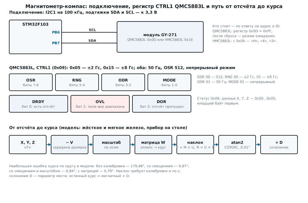
Which chip is on the board. The driver first asks address 0x0D. If it answers, the driver writes the reset bit 0x80 into CTRL2, waits 20 ms, reads the ID and CTRL1: the QMC5883L has ID 0xFF, and after reset the two low bits of CTRL1 are zero, standby mode. Betaflight does the same and explains why in a comment: 0xFF alone is not enough, such a byte is also read from a bus where nobody answers. If nothing is found — address 0x1E and three ID bytes from 0x0A:
/* кто на шине: QMC5883L — адрес 0x0D, ID 0xFF и режим ожидания после сброса; HMC5883L — адрес 0x1E, ID «H43» */
int mag_probe(mag_t *d)
{
    uint8_t b[3];
    d->type = MAG_NONE;
    if (mag_ping(d, QMC_ADDR) == MAG_OK) {
        d->addr = QMC_ADDR;
        (void)mag_write_reg(d, QMC_CTRL2, QMC_SOFT_RST);        /* сброс: после него — режим ожидания */
        mag_port_delay_us(20000u);
        if (mag_read_regs(d, QMC_ID, b, 1) == MAG_OK && b[0] == QMC_ID_VAL
            && mag_read_regs(d, QMC_CTRL1, b + 1, 1) == MAG_OK && (b[1] & QMC_MODE_MASK) == 0u) {
            d->type = MAG_QMC;                                  /* одного 0xFF мало: так читается и пустая шина */
            return MAG_QMC;
        }
    }
    if (mag_ping(d, HMC_ADDR) == MAG_OK) {
        d->addr = HMC_ADDR;
        if (mag_read_regs(d, HMC_ID_A, b, 3) == MAG_OK && b[0] == 'H' && b[1] == '4' && b[2] == '3') {
            d->type = MAG_HMC;
            return MAG_HMC;
        }
    }
    return MAG_NONE;
}
In the model, on a QMC5883L board the scan of addresses 0x08…0x77 finds
only 0x0D, and identification takes 4 exchanges: the address, a write
0A 80, a read 0D → FF, a read 09 → 00. On an HMC5883L board —
2 exchanges and the ID "H43". If both are on the bus, the driver takes
the QMC5883L; if nobody is there — MAG_NONE, and the firmware waits.
99г.2 Registers: mode, range, status and conversion to nanotesla
QMC5883L. Everything is set by CTRL1 (0x09): the two high bits are OSR, how many times the chip averages internally; bits 5:4 are the range RNG, 00 — ±2 G, 01 — ±8 G; bits 3:2 are the rate ODR, 00…11 — 10, 50, 100 and 200 Hz; bits 1:0 are the mode, 00 — standby, 01 — continuous. The shifts 6, 4, 2 and 0 are as in Betaflight. CTRL2 (0x0A): 0x80 — software reset. Register 0x0B is the SET/RESET period: short pulses that re-magnetise the sensing elements. Betaflight writes 0x01 there — so does this driver; the manufacturer, per its documentation, recommends the same (not verified). In the model this register and OSR do not affect the readings.
/* непрерывный режим: QMC — 50 Гц, OSR 512, ±2 или ±8 Гс; HMC — 15 Гц, 8 отсчётов в среднем, ±1,3 или ±8,1 Гс */
int mag_init(mag_t *d, int range8)
{
    int rc;
    if (d->type == MAG_QMC) {
        if ((rc = mag_write_reg(d, QMC_SETRESET, 0x01u)) != MAG_OK)
            return rc;
        d->lsb_per_g = range8 ? QMC_LSB_8G : QMC_LSB_2G;
        return mag_write_reg(d, QMC_CTRL1, (uint8_t)(QMC_OSR_512 | (range8 ? QMC_RNG_8G : 0u) | QMC_ODR_50HZ | QMC_MODE_CONT));
    }
In the model the QMC5883L receives 0B 01 and 09 05 for ±2 G or
09 15 for ±8 G. The HMC5883L — 00 70 (8 samples averaged, 15 Hz),
01 20 (±1.3 G) or 01 E0 (±8.1 G) and 02 00 — continuous mode.
After reset the QMC5883L sits in standby and gives no data: without a
write to CTRL1 the driver waits for readiness for 211 ms and returns
MAG_E_TIMEOUT, −4.
Status. On the QMC5883L it is register 0x06: DRDY (bit 0) — a new sample is there, OVL (bit 1) — the field is out of range, DOR (bit 2) — a sample was skipped, the previous one was never read. Per the manufacturer's documentation reading the data clears DRDY and DOR (not verified; the model does so). The driver polls the status every 5 ms and reads six bytes when DRDY = 1. At 100 kHz a status read is 39 SCL clocks, the data 84, together 1230 µs per sample. In the model, 20 reads in a row at 50 Hz: without pauses DOR never appeared; with a 30 ms pause — 10 times; with a 100 ms pause — 19: samples are lost when reading more rarely than their rate.
Conversion to nanotesla. 1 G = 100 µT = 100 000 nT. The QMC5883L per the manufacturer's documentation gives 12000 LSB/G at ±2 G and 3000 at ±8 G; the HMC5883L gain comes from the Zephyr table: 1370, 1090, 820, 660, 440, 390, 330 and 230 LSB/G for ±0.88 … ±8.1 G. The division must be in integers, in 64 bits: 32767 × 100 000 does not fit into 32 bits.
/* 1 Гс = 100 мкТл = 100 000 нТл: нТл = raw × 100 000 / (LSB на гаусс) */
int32_t mag_raw_to_nt(int32_t raw, int32_t lsb_per_g)
{
    return (int32_t)rdiv((int64_t)raw * 100000, lsb_per_g);
}
| QMC5883L ±2 G | QMC5883L ±8 G | HMC5883L ±1.3 G | |
|---|---|---|---|
| LSB per gauss | 12000 | 3000 | 1090 |
| 1 LSB | 8 nT | 33 nT | 92 nT |
| field of 50 µT | 6000 | 1500 | 545 |
| largest code | 32767 — 273 058 nT | 32767 — 1 092 233 nT | 2047 — 187 798 nT |
The Earth's field in the model is 50 µT with an inclination of 70°: 17.10 µT horizontally, 46.98 µT downwards. The location is notional. The horizontal field is three times smaller than the total, and the heading is caught precisely from it.
In the model the device with no iron nearby is turned to 30°. The
QMC5883L returns the bytes E8 06 F5 03 FA E9 — X, Y, Z low byte first:
1768, 1013, −5638, that is 14 733, 8442, −46 983 nT. The HMC5883L —
00 A1 FE 00 00 5C: 161, then −512 — that is Z, then 92 — Y; in
nanotesla 14 771, 8440, −46 972. The X, Z, Y order is the same in Zephyr
and Betaflight.
99г.3 Heading through atan2 and why it lies without calibration
The board axes in this section: x — forward, y — left, z — up. When the device lies level, the horizontal part of the field points to magnetic north, and the heading is the angle of the x axis from it, clockwise: atan2(My, Mx). The device faces east — north is on the left, along +y, and the heading is 90°.
The F103 has no FPU, and atan2f on it is library float. Integers are
enough for a heading: the CORDIC method rotates the vector onto the x
axis in twenty steps, each a shift and an addition, and sums the rotation
angles from the table atan(2⁻ⁱ). A short vector is stretched first,
otherwise the shifts would zero it. On 3000 random vectors of length 10
to 10¹² the largest error against atan2 with double is 0.54
hundredths of a degree.
/* atan(2^−i) в десятитысячных градуса: CORDIC поворачивает вектор на ось x и складывает углы поворотов */
static const int32_t atan_tab[20] = {450000, 265651, 140362, 71250, 35763, 17899, 8952, 4476, 2238, 1119,
                                     560, 280, 140, 70, 35, 17, 9, 4, 2, 1};
Why the compass lies. A magnet next to the sensor — a speaker, a motor, a screw with a magnetised head — adds a constant vector: this is hard iron. The circle traced by the tip of the field vector as the device turns is shifted. Steel nearby — a case, a shield plate — changes the field differently along different directions: this is soft iron, the circle becomes an ellipse. In the model the hard iron is 28, −15 and 22 µT, the soft iron a matrix with 1.15 and 0.88 along x and y and 0.10 between them. The heading error when level, the largest around a circle of 360 positions and in eight directions:
| What is nearby | 0° | 45° | 90° | 135° | 180° | 225° | 270° | 315° | around the circle, max |
|---|---|---|---|---|---|---|---|---|---|
| nothing | −0.03 | 0.18 | −0.11 | 0.16 | 0.19 | −0.12 | 0.03 | −0.04 | 0.56 |
| hard iron | −18.40 | −49.06 | −85.73 | −145.62 | 125.93 | 75.37 | 41.11 | 10.94 | 179.85 |
| soft iron | 4.93 | −6.73 | −6.60 | 8.60 | 5.14 | −7.00 | −6.45 | 8.34 | 9.83 |
| both | −15.59 | −49.10 | −89.92 | −155.24 | 116.47 | 70.58 | 41.20 | 14.00 | 179.24 |
Without disturbances only noise remains — 0.56°. Soft iron gives an error that changes sign four times per turn, up to 9.83°. But hard iron of 28 µT is larger than the whole horizontal field, 17.10 µT: the circle has moved so far that the origin is outside it, and the compass shows almost anything — up to 179.85°.
99г.4 Calibration: offset, scale and matrix
Calibration means turning the device around and looking at what the circle has become. The driver keeps the smallest and largest values along x, y, z and also along the diagonals x + y and x − y. The memory is ten numbers, no matter how many points arrive:
/* одна точка при вращении: наименьшее и наибольшее по x, y, z и по диагоналям x + y, x − y */
void magcal_add(magcal_t *c, const int32_t m[3])
{
    const int32_t p[5] = {m[0], m[1], m[2], m[0] + m[1], m[0] - m[1]};
    for (int i = 0; i < 5; i++) {
        if (p[i] < c->lo[i])
            c->lo[i] = p[i];
        if (p[i] > c->hi[i])
            c->hi[i] = p[i];
    }
    c->n++;
}
Then three steps. Offset — the middle of the range on each axis: removes hard iron. Scale — the half-range of each axis relative to the mean: an ellipse stretched along x or y becomes a circle. Matrix — if the ellipse is rotated, per-axis scale cannot straighten it. The range along a direction does not depend on the offset, so the four half-ranges hx, hy, hu, hv directly give the shape of the ellipse P = [[hx², q], [q, hy²]], q = (hu² − hv²) / 4. The matrix needed is P^(−1/2); for 2×2 it has a formula without eigenvectors: W is proportional to [[hy² + s, −q], [−q, hx² + s]], where s = √det P. Only multiplications and an integer root are needed. This is two dimensions — the XY plane; the full ellipsoid in three is in 99б.5.
Experiment: the device on a table makes one turn in 600 samples (12 s at 50 Hz), then the heading error is checked in 8 directions and around the circle:
| Calibration | 0° | 45° | 90° | 135° | 180° | 225° | 270° | 315° | around the circle, max | RMS |
|---|---|---|---|---|---|---|---|---|---|---|
| none | −15.59 | −49.15 | −90.02 | −155.05 | 116.56 | 70.71 | 41.13 | 14.05 | 179.48 | 83.82 |
| offset | 4.93 | −6.77 | −6.63 | 8.39 | 4.88 | −6.75 | −6.42 | 8.59 | 9.87 | 6.71 |
| offset and scale | 6.46 | 0.32 | −5.15 | 1.24 | 6.80 | 0.41 | −4.71 | 1.09 | 6.84 | 4.15 |
| offset and matrix | −0.07 | −0.06 | −0.08 | −0.12 | 0.22 | 0.10 | 0.13 | −0.09 | 0.79 | 0.29 |
The offset is found as 27 970 and −14 983 nT against the real 28 000 and −15 000. On its own it leaves the soft-iron error — 9.87°. The per-axis scale (0.885 along x, 1.149 along y) removes only part of it: the ellipse in the model is rotated. The matrix — 0.881, −0.099 and 1.147 — turns the ellipse into a circle of radius 16 914…17 259 nT, and the error falls to 0.79° — almost down to the noise. W·A differs from the identity matrix by less than 1 %.
One turn on a table is not enough if tilt is needed: on a table z hardly
changes, its range is noise, and the driver marks z as not checked
(z_ok = 0) and leaves the z offset alone. To find it too, the device is
turned in all directions for 30 s: in the model 1500 random positions.
Then the offset is 27 908, −14 954 and 22 008 nT, z is checked, and the
heading error when level around the circle is 0.92°. An HMC5883L with
the same disturbances after a turn of 200 samples (15 Hz) — 0.69°.
99г.5 Tilt from the accelerometer and magnetic declination
atan2(My, Mx) is right only while the device is level. Tilt it — and part of the vertical field gets into x and y, and here it is almost three times stronger than the horizontal one. The accelerometer does the correction (section 99): at rest it shows "up". The cross product of the field and "up" points east, "up" times east points north; the heading is the angle of the x axis between them. No sines, no tilt angles — only multiplications in 64 bits:
/* с наклоном: U — «вверх» по акселерометру, восток E = M × U, север N = U × E; курс = atan2(Ex·|U|, Nx).
 * Ни синусов, ни углов наклона: только векторные произведения в 64 битах */
int32_t mag_heading_tilt(const int32_t m[3], const int32_t acc_mg[3])
{
    const int64_t mx = m[0], my = m[1], mz = m[2], ux = acc_mg[0], uy = acc_mg[1], uz = acc_mg[2];
    const int64_t ex = my * uz - mz * uy, ey = mz * ux - mx * uz, ez = mx * uy - my * ux;
    const int64_t nx = uy * ez - uz * ey;
    const int64_t u = (int64_t)isqrt64((uint64_t)(ux * ux + uy * uy + uz * uz));
    return mag_atan2_cdeg(ex * u, nx);
}
In the model, after calibration in all directions, the largest error around the circle:
| Pitch, roll | 0°, 0° | 5°, 0° | 10°, 0° | 0°, 10° | 15°, −10° | 30°, 0° | 45°, 20° |
|---|---|---|---|---|---|---|---|
| without correction | 0.71 | 13.81 | 29.08 | 29.80 | 63.25 | 179.31 | 178.98 |
| with correction | 1.21 | 1.41 | 1.15 | 1.31 | 1.13 | 1.45 | 1.29 |
A tilt of 5° already gives 13.81° of error, 10° — about 30°. With the correction — about a degree at any tilt. When level it is slightly worse than the simple formula, 1.21° against 0.71°: the accelerometer noise in the model is 2 mg, and it also gets into the heading. The correction is valid only at rest: with an acceleration of 0.1 g forward the error is 17.14°, sideways — 16.43°. A device that drives and shakes needs a gyroscope and a filter — 99б.
If z was not calibrated (a turn on a table, z_ok = 0), the tilt
correction works with a z offset of zero: at a pitch of 15° and a roll of
−10° — 21.76° of error. In that case the firmware computes the heading
with the flat formula only.
Declination. A compass points to magnetic north, a map to true north. The angle between them is the magnetic declination D, its own for every place and slowly changing over the years; it is taken from a model of the Earth's magnetic field for one's location. True heading = magnetic + D, an easterly declination is plus:
/* истинный курс = магнитный + склонение (восточное — плюс), по модулю 360° */
int32_t mag_true_heading(int32_t mag_cdeg, int32_t decl_cdeg)
{
    int32_t t = (mag_cdeg + decl_cdeg) % 36000;
    return t < 0 ? t + 36000 : t;
}
In the model D = +10.00° — a notional value. Without it the true heading in 8 directions is off by −9.46…−10.74°, with it — by no more than 0.70° in absolute value.
99г.6 Disturbances: current-carrying wires, motors and speakers
Calibration removes only what is fixed relative to the sensor and does not change in time. A speaker magnet screwed to the device is hard iron: it calibrates out. A current in a nearby wire does not, if it switches on and off. The field of a long straight wire is μ0·I / (2π·r), 2 µT per ampere at 10 cm:
| Current | 2 cm | 5 cm | 10 cm | 20 cm |
|---|---|---|---|---|
| 0.1 A | 1.00 µT | 0.40 µT | 0.20 µT | 0.10 µT |
| 0.5 A | 5.00 µT | 2.00 µT | 1.00 µT | 0.50 µT |
| 1 A | 10.00 µT | 4.00 µT | 2.00 µT | 1.00 µT |
| 2 A | 20.00 µT | 8.00 µT | 4.00 µT | 2.00 µT |
| 5 A | 50.00 µT | 20.00 µT | 10.00 µT | 5.00 µT |
Compare this with the 17.10 µT of the horizontal field. In the model the wire is 5 cm under the sensor, the current is switched on after calibration; the largest heading error around the circle: 0.1 A — 2.22°, 0.5 A — 8.39°, 1 A — 16.18°, 2 A — 33.10°, 5 A — 176.83°. If the same current of 2 A goes there and back through a pair of wires 2 mm apart, the field at 5 cm is 0.31 µT, and the error is 1.86°. If the calibration was done with the 2 A current on, the heading is accurate with it — 0.71°, and without it — 32.62°.
Hence the rules. Do not run power wires near the sensor; keep the forward and return wires together or twisted. A motor is both a magnet and a current in the windings that changes with the load: the sensor is moved away from it, onto a mast, as on drones. Calibrate in the assembly in which the device works, and with the currents that always flow.
99г.7 Pitfalls
The module does not answer at the address from the example. The board carries a QMC5883L and the example is for the HMC5883L: address 0x0D, not 0x1E. In the model — a NACK, code −1. A bus scan (99г.1) shows at once who is there.
It answers at 0x0D, but the heading is garbage. An HMC5883L driver moved to address 0x0D reads foreign registers: it takes CTRL1 for the status, and half of Y, Z, the status and the temperature for the data. In the model the heading error is up to 180.00°. The register maps of these chips differ entirely.
The HMC5883L heading jumps by 90° and more. The second data word was taken for Y, but it is Z: the memory holds X, Z, Y. In the model such parsing gives up to 179.89°.
The QMC5883L gives no data. After reset it is in standby: without a write to CTRL1 DRDY will not appear. In the model — a timeout after 211 ms.
A magnet nearby — the heading lies even after calibration. At ±2 G the QMC5883L code is limited to 16 bits, 273 058 nT. In the model the offset from the magnet is 265 µT: part of the samples hit the limit and OVL is set. During calibration 220 samples of 600 are discarded, the x offset is found as 259 062 nT instead of 265 000, and then 66 positions of 180 overflow, and the error of the rest is up to 27.38°. At ±8 G the same place gives not a single OVL, the offset is 264 966 nT, the error 0.75°. Best of all — remove the magnet.
The z axis points the wrong way. The sign of the magnetometer z is flipped relative to the accelerometer — for instance, it was "converted" to axes with z down while the other axes were left alone. When level this is invisible: 0.71° without the correction and 1.30° with it. At a tilt of 15° and −10° — 178.42°. The axis triples of both sensors must be right-handed and coincide.
The board is mounted rotated. The module was turned by 90° — x points sideways. When level the heading is shifted by 90.57°, under tilt the error reaches 179.86°: the magnetometer and accelerometer axes have diverged. Before the formulas the axes are remapped into the device axes; the remaining constant shift is checked by pointing the device at a known landmark.
Power and levels. On a module with a regulator the pull-ups usually go to its output; the bare chip is powered below 5 V per the manufacturer's documentation (not verified). PB6 and PB7 are FT (p. 32): they will survive 5 V pull-ups, but 3.3 V is better.
99г.8 Summary
- A GY-271 board may carry a QMC5883L (0x0D, ID 0xFF) or an HMC5883L (0x1E, ID "H43"); identification is by address, ID and the mode after reset, 4 and 2 exchanges in the model.
- QMC5883L: CTRL1 0x05 — ±2 G, 0x15 — ±8 G, 50 Hz, continuous mode; status 0x06 — DRDY, OVL, DOR; data X, Y, Z low byte first. HMC5883L — X, Z, Y high byte first.
- Nanotesla in integers: raw × 100 000 / LSB per gauss in 64 bits; 1 LSB is 8 nT on the QMC5883L at ±2 G, 92 nT on the HMC5883L at ±1.3 G.
- Heading by CORDIC without
float: 0.54 hundredths of a degree of error. - Calibration by largest and smallest: without it 179.48°, with the offset 9.87°, with the scale 6.84°, with the matrix 0.79°.
- A tilt of 10° without correction — 29.08°, with accelerometer correction — 1.15°; for it z must be calibrated by turning the device in all directions.
- True heading = magnetic + the declination of the place.
- A wire with 1 A at 5 cm — 16.18° of error; a twisted pair with 2 A — 1.86°.
Full sources
mag99e.h — registers of both chips, error codes, port and functions of the driver, calibration and heading.
/* mag99e.h — раздел 99г: магнитометр-компас QMC5883L / HMC5883L, калибровка и курс — целыми, без регистров
 * микроконтроллера. Драйвер говорит с микросхемой только через порт (mag_port_*): в прошивке fw99e.c его делает
 * I2C1 STM32F103, в стенде host99e.c — модель model99e.py.
 * QMC5883L: адрес 0x0D, карта регистров и биты — как в compass_qmc5883.c Betaflight; 12000 и 3000 LSB/Гс —
 * по документации производителя (не проверено). HMC5883L: адрес 0x1E — как в compass_hmc5883l.c Betaflight;
 * регистры, ID «H43», порядок X, Z, Y и усиления — как в hmc5883l.h/.c Zephyr 4.4.2.
 * Оси платы: x — вперёд, y — влево, z — вверх (правая тройка); курс — от севера по часовой стрелке. */
#ifndef MAG99E_H
#define MAG99E_H
#include <stdint.h>

/* ── QMC5883L ─────────────────────────────────────────────────────────── */
#define QMC_ADDR        0x0Du
#define QMC_DATA        0x00u           /* X, Y, Z — по два байта, младший первым */
#define QMC_STATUS      0x06u
#define QMC_ST_DRDY     0x01u           /* новые данные */
#define QMC_ST_OVL      0x02u           /* поле вне диапазона */
#define QMC_ST_DOR      0x04u           /* отсчёт пропущен: данные не прочитаны вовремя */
#define QMC_CTRL1       0x09u           /* OSR [7:6], RNG [5:4], ODR [3:2], MODE [1:0] */
#define QMC_CTRL2       0x0Au
#define QMC_SETRESET    0x0Bu           /* период SET/RESET */
#define QMC_ID          0x0Du
#define QMC_ID_VAL      0xFFu
#define QMC_MODE_CONT   0x01u
#define QMC_MODE_MASK   0x03u
#define QMC_ODR_50HZ    (1u << 2)
#define QMC_RNG_8G      (1u << 4)       /* 0 — ±2 Гс */
#define QMC_OSR_512     (0u << 6)
#define QMC_SOFT_RST    0x80u
#define QMC_LSB_2G      12000           /* LSB на гаусс при ±2 Гс */
#define QMC_LSB_8G      3000            /* при ±8 Гс */

/* ── HMC5883L ─────────────────────────────────────────────────────────── */
#define HMC_ADDR        0x1Eu
#define HMC_CRA         0x00u           /* усреднение [6:5], частота [4:2], режим измерения [1:0] */
#define HMC_CRB         0x01u           /* усиление [7:5] */
#define HMC_MODE        0x02u
#define HMC_DATA        0x03u           /* X, Z, Y — по два байта, старший первым */
#define HMC_STATUS      0x09u
#define HMC_ST_RDY      0x01u
#define HMC_ID_A        0x0Au           /* три байта: 'H', '4', '3' */
#define HMC_CRA_VAL     0x70u           /* 8 отсчётов в среднем (3 << 5), 15 Гц (4 << 2), без смещения */
#define HMC_OVF         (-4096)         /* так микросхема помечает переполнение оси */

#define MAG_POLL_US     5000u           /* опрос готовности */
#define MAG_POLL_TRIES  40u             /* 200 мс: у HMC5883L отсчёт раз в 67 мс */

enum { MAG_NONE = 0, MAG_QMC = 1, MAG_HMC = 2 };
enum { MAG_OK = 0, MAG_E_NACK = -1, MAG_E_BUS = -2, MAG_E_ID = -3, MAG_E_TIMEOUT = -4, MAG_E_OVL = -5, MAG_E_CAL = -6 };
enum { CAL_NONE = 0, CAL_OFFSET = 1, CAL_SCALE = 2, CAL_MATRIX = 3 };

typedef struct {
    uint8_t type, addr;
    int32_t lsb_per_g;
    uint32_t xfers, errors, samples, dor, ovl;
} mag_t;

typedef struct {
    int32_t lo[5], hi[5];               /* x, y, z, x + y, x − y — нТл */
    uint32_t n;
} magcal_t;

typedef struct {
    uint8_t mode, z_ok;
    int32_t v[3];                       /* смещение — жёсткое железо, нТл */
    int32_t s[3];                       /* масштаб по осям, Q14 */
    int32_t w[2][2];                    /* матрица XY — мягкое железо, Q14 */
} magcorr_t;

/* ── порт: в прошивке — I2C1, в стенде — строки к модели ──────────────── */
/* ntx байт записи, затем (если nrx) повторный старт и nrx байт чтения; ntx = nrx = 0 — только адрес.
 * 0, MAG_E_NACK или MAG_E_BUS */
int mag_port_xfer(uint8_t addr7, const uint8_t *tx, uint32_t ntx, uint8_t *rx, uint32_t nrx);
void mag_port_delay_us(uint32_t us);

/* ── драйвер ──────────────────────────────────────────────────────────── */
int mag_ping(mag_t *d, uint8_t addr7);
int mag_write_reg(mag_t *d, uint8_t reg, uint8_t val);
int mag_read_regs(mag_t *d, uint8_t reg, uint8_t *buf, uint32_t n);
int mag_probe(mag_t *d);
int mag_init(mag_t *d, int range8);
int mag_read_raw(mag_t *d, int16_t raw[3]);
int32_t mag_raw_to_nt(int32_t raw, int32_t lsb_per_g);
int mag_read_nt(mag_t *d, int32_t nt[3]);
int mag_read_avg(mag_t *d, uint32_t n, int32_t nt[3]);

/* ── калибровка ───────────────────────────────────────────────────────── */
void magcal_reset(magcal_t *c);
void magcal_add(magcal_t *c, const int32_t m[3]);
int magcal_solve(const magcal_t *c, int mode, magcorr_t *k);
void magcorr_apply(const magcorr_t *k, const int32_t m[3], int32_t out[3]);

/* ── курс, сотые доли градуса 0…35999 ─────────────────────────────────── */
int32_t mag_atan2_cdeg(int64_t y, int64_t x);
int32_t mag_heading_flat(const int32_t m[3]);
int32_t mag_heading_tilt(const int32_t m[3], const int32_t acc_mg[3]);
int32_t mag_true_heading(int32_t mag_cdeg, int32_t decl_cdeg);

#endif
mag99e.c — driver: identification, setup, reading, conversion to nanotesla, calibration, CORDIC, tilt, declination.
/* mag99e.c — раздел 99г: драйвер QMC5883L / HMC5883L, калибровка и курс. Один и тот же файл собирается в прошивку
* (armclang, Cortex-M3) и в стенд на компьютере (gcc): микроконтроллера он не знает, только порт mag_port_*.
* Всё целыми: поле — в нанотеслах, курс — в сотых долях градуса, у F103 нет FPU. */
#include "mag99e.h"
#define Q14 16384
#define CAL_MIN_NT 5000 /* размах меньше 5 мкТл — эту ось не поворачивали */
#define ASR(v, i) ((v) >= 0 ? (v) >> (i) : ~(~(v) >> (i))) /* сдвиг вправо со знаком, как деление с округлением вниз */
static const uint16_t hmc_gain[8] = {1370, 1090, 820, 660, 440, 390, 330, 230}; /* LSB/Гс: ±0,88 … ±8,1 Гс */
static int xfer_done(mag_t *d, int rc)
{
d->xfers++;
if (rc)
d->errors++;
return rc;
}
int mag_ping(mag_t *d, uint8_t addr7)
{
return xfer_done(d, mag_port_xfer(addr7, 0, 0, 0, 0));
}
int mag_write_reg(mag_t *d, uint8_t reg, uint8_t val)
{
uint8_t b[2] = {reg, val};
return xfer_done(d, mag_port_xfer(d->addr, b, 2, 0, 0));
}
/* номер регистра, повторный старт, n байт подряд: указатель регистров в микросхеме идёт сам */
int mag_read_regs(mag_t *d, uint8_t reg, uint8_t *buf, uint32_t n)
{
return xfer_done(d, mag_port_xfer(d->addr, ®, 1, buf, n));
}
/* кто на шине: QMC5883L — адрес 0x0D, ID 0xFF и режим ожидания после сброса; HMC5883L — адрес 0x1E, ID «H43» */
int mag_probe(mag_t *d)
{
uint8_t b[3];
d->type = MAG_NONE;
if (mag_ping(d, QMC_ADDR) == MAG_OK) {
d->addr = QMC_ADDR;
(void)mag_write_reg(d, QMC_CTRL2, QMC_SOFT_RST); /* сброс: после него — режим ожидания */
mag_port_delay_us(20000u);
if (mag_read_regs(d, QMC_ID, b, 1) == MAG_OK && b[0] == QMC_ID_VAL
&& mag_read_regs(d, QMC_CTRL1, b + 1, 1) == MAG_OK && (b[1] & QMC_MODE_MASK) == 0u) {
d->type = MAG_QMC; /* одного 0xFF мало: так читается и пустая шина */
return MAG_QMC;
}
}
if (mag_ping(d, HMC_ADDR) == MAG_OK) {
d->addr = HMC_ADDR;
if (mag_read_regs(d, HMC_ID_A, b, 3) == MAG_OK && b[0] == 'H' && b[1] == '4' && b[2] == '3') {
d->type = MAG_HMC;
return MAG_HMC;
}
}
return MAG_NONE;
}
/* непрерывный режим: QMC — 50 Гц, OSR 512, ±2 или ±8 Гс; HMC — 15 Гц, 8 отсчётов в среднем, ±1,3 или ±8,1 Гс */
int mag_init(mag_t *d, int range8)
{
int rc;
if (d->type == MAG_QMC) {
if ((rc = mag_write_reg(d, QMC_SETRESET, 0x01u)) != MAG_OK)
return rc;
d->lsb_per_g = range8 ? QMC_LSB_8G : QMC_LSB_2G;
return mag_write_reg(d, QMC_CTRL1, (uint8_t)(QMC_OSR_512 | (range8 ? QMC_RNG_8G : 0u) | QMC_ODR_50HZ | QMC_MODE_CONT));
}
if (d->type == MAG_HMC) {
uint8_t g = range8 ? 7u : 1u;
if ((rc = mag_write_reg(d, HMC_CRA, HMC_CRA_VAL)) != MAG_OK)
return rc;
if ((rc = mag_write_reg(d, HMC_CRB, (uint8_t)(g << 5))) != MAG_OK)
return rc;
d->lsb_per_g = hmc_gain[g];
return mag_write_reg(d, HMC_MODE, 0x00u); /* 0 — непрерывный; после включения — одиночный */
}
return MAG_E_ID;
}
/* дождаться готовности и прочитать X, Y, Z; у HMC5883L в памяти порядок X, Z, Y и старший байт первым */
int mag_read_raw(mag_t *d, int16_t raw[3])
{
uint8_t st, b[6];
int rc;
const uint8_t hmc = d->type == MAG_HMC;
if (d->type != MAG_QMC && !hmc)
return MAG_E_ID;
for (uint32_t i = 0;; i++) {
if ((rc = mag_read_regs(d, hmc ? HMC_STATUS : QMC_STATUS, &st, 1)) != MAG_OK)
return rc;
if (st & (hmc ? HMC_ST_RDY : QMC_ST_DRDY))
break;
if (i + 1u >= MAG_POLL_TRIES)
return MAG_E_TIMEOUT; /* QMC в режиме ожидания: CTRL1 не записан */
mag_port_delay_us(MAG_POLL_US);
}
if ((rc = mag_read_regs(d, hmc ? HMC_DATA : QMC_DATA, b, 6)) != MAG_OK)
return rc;
d->samples++;
if (!hmc) {
for (int k = 0; k < 3; k++)
raw[k] = (int16_t)(b[2 * k] | b[2 * k + 1] << 8); /* младший байт первым */
if (st & QMC_ST_DOR)
d->dor++;
if (st & QMC_ST_OVL) {
d->ovl++;
return MAG_E_OVL;
}
return MAG_OK;
}
raw[0] = (int16_t)(b[0] << 8 | b[1]);
raw[2] = (int16_t)(b[2] << 8 | b[3]); /* вторым идёт Z, а не Y */
raw[1] = (int16_t)(b[4] << 8 | b[5]);
if (raw[0] == HMC_OVF || raw[1] == HMC_OVF || raw[2] == HMC_OVF) {
d->ovl++;
return MAG_E_OVL;
}
return MAG_OK;
}
static int64_t rdiv(int64_t a, int64_t b) /* b > 0, округление к ближайшему */
{
return a >= 0 ? (a + b / 2) / b : -((-a + b / 2) / b);
}
/* 1 Гс = 100 мкТл = 100 000 нТл: нТл = raw × 100 000 / (LSB на гаусс) */
int32_t mag_raw_to_nt(int32_t raw, int32_t lsb_per_g)
{
return (int32_t)rdiv((int64_t)raw * 100000, lsb_per_g);
}
int mag_read_nt(mag_t *d, int32_t nt[3])
{
int16_t raw[3] = {0, 0, 0};
int rc = mag_read_raw(d, raw);
for (int k = 0; k < 3; k++)
nt[k] = mag_raw_to_nt(raw[k], d->lsb_per_g);
return rc;
}
int mag_read_avg(mag_t *d, uint32_t n, int32_t nt[3])
{
int64_t s[3] = {0, 0, 0};
int32_t m[3];
int rc;
if (!n)
return MAG_E_CAL;
for (uint32_t i = 0; i < n; i++) {
if ((rc = mag_read_nt(d, m)) != MAG_OK)
return rc;
for (int k = 0; k < 3; k++)
s[k] += m[k];
}
for (int k = 0; k < 3; k++)
nt[k] = (int32_t)rdiv(s[k], (int64_t)n);
return MAG_OK;
}
void magcal_reset(magcal_t *c)
{
for (int i = 0; i < 5; i++) {
c->lo[i] = INT32_MAX;
c->hi[i] = INT32_MIN;
}
c->n = 0;
}
/* одна точка при вращении: наименьшее и наибольшее по x, y, z и по диагоналям x + y, x − y */
void magcal_add(magcal_t *c, const int32_t m[3])
{
const int32_t p[5] = {m[0], m[1], m[2], m[0] + m[1], m[0] - m[1]};
for (int i = 0; i < 5; i++) {
if (p[i] < c->lo[i])
c->lo[i] = p[i];
if (p[i] > c->hi[i])
c->hi[i] = p[i];
}
c->n++;
}
static uint64_t isqrt64(uint64_t v)
{
uint64_t r = 0, b = 1ull << 62;
while (b > v)
b >>= 2;
while (b) {
if (v >= r + b) {
v -= r + b;
r = (r >> 1) + b;
} else {
r >>= 1;
}
b >>= 2;
}
return r;
}
/* Смещение — середина размаха. Масштаб — полуразмах каждой оси к среднему. Матрица XY: эллипс с полуширинами
* hx, hy и hu, hv по диагоналям (размах не зависит от смещения) — P = [[p, q], [q, r]], p = hx², r = hy²,
* q = (hu² − hv²) / 4; W = P^(−1/2) · √(√det P) = [[r + s, −q], [−q, p + s]] / (√s · √(p + r + 2s)), s = √det P.
* Эллипс становится окружностью радиуса √(ab) — среднего геометрического полуосей. Квадраты — в единицах 8 нТл. */
int magcal_solve(const magcal_t *c, int mode, magcorr_t *k)
{
int32_t h[5], mid[3];
int64_t p, r, q, det, s, t, kk;
k->mode = CAL_NONE;
k->z_ok = 0;
for (int i = 0; i < 3; i++) {
k->v[i] = 0;
k->s[i] = Q14;
}
k->w[0][0] = k->w[1][1] = Q14;
k->w[0][1] = k->w[1][0] = 0;
if (mode == CAL_NONE)
return MAG_OK;
if (c->n < 2u || mode < CAL_NONE || mode > CAL_MATRIX)
return MAG_E_CAL;
for (int i = 0; i < 5; i++)
h[i] = (int32_t)(((int64_t)c->hi[i] - c->lo[i]) / 2);
for (int i = 0; i < 3; i++)
mid[i] = (int32_t)(((int64_t)c->hi[i] + c->lo[i]) / 2);
if (h[0] < CAL_MIN_NT || h[1] < CAL_MIN_NT)
return MAG_E_CAL; /* прибор не повернули кругом */
k->z_ok = (uint8_t)(4 * (int64_t)h[2] >= (int64_t)h[0] + h[1]); /* z повернули хотя бы на полразмаха xy */
k->v[0] = mid[0];
k->v[1] = mid[1];
k->v[2] = k->z_ok ? mid[2] : 0;
k->mode = (uint8_t)mode;
if (mode == CAL_SCALE) {
int64_t avg = k->z_ok ? ((int64_t)h[0] + h[1] + h[2]) / 3 : ((int64_t)h[0] + h[1]) / 2;
k->w[0][0] = k->s[0] = (int32_t)rdiv(avg * Q14, h[0]);
k->w[1][1] = k->s[1] = (int32_t)rdiv(avg * Q14, h[1]);
if (k->z_ok)
k->s[2] = (int32_t)rdiv(avg * Q14, h[2]);
} else if (mode == CAL_MATRIX) {
p = (int64_t)(h[0] / 8) * (h[0] / 8);
r = (int64_t)(h[1] / 8) * (h[1] / 8);
q = ((int64_t)(h[3] / 8) * (h[3] / 8) - (int64_t)(h[4] / 8) * (h[4] / 8)) / 4;
det = p * r - q * q;
if (det <= 0)
return MAG_E_CAL;
s = (int64_t)isqrt64((uint64_t)det);
t = (int64_t)isqrt64((uint64_t)(p + r + 2 * s));
kk = (int64_t)isqrt64((uint64_t)s) * t;
k->w[0][0] = (int32_t)rdiv((r + s) * Q14, kk);
k->w[0][1] = k->w[1][0] = (int32_t)rdiv(-q * Q14, kk);
k->w[1][1] = (int32_t)rdiv((p + s) * Q14, kk);
if (k->z_ok)
k->s[2] = (int32_t)rdiv((int64_t)isqrt64((uint64_t)s) * 8 * Q14, h[2]);
}
return MAG_OK;
}
void magcorr_apply(const magcorr_t *k, const int32_t m[3], int32_t out[3])
{
const int64_t d0 = (int64_t)m[0] - k->v[0], d1 = (int64_t)m[1] - k->v[1], d2 = (int64_t)m[2] - k->v[2];
out[0] = (int32_t)rdiv(k->w[0][0] * d0 + k->w[0][1] * d1, Q14);
out[1] = (int32_t)rdiv(k->w[1][0] * d0 + k->w[1][1] * d1, Q14);
out[2] = (int32_t)rdiv(k->s[2] * d2, Q14);
}
/* atan(2^−i) в десятитысячных градуса: CORDIC поворачивает вектор на ось x и складывает углы поворотов */
static const int32_t atan_tab[20] = {450000, 265651, 140362, 71250, 35763, 17899, 8952, 4476, 2238, 1119,
560, 280, 140, 70, 35, 17, 9, 4, 2, 1};
/* угол вектора (x, y) против часовой стрелки от оси x, сотые доли градуса 0…35999; без float и libm */
int32_t mag_atan2_cdeg(int64_t y, int64_t x)
{
int32_t a = 0, xi, yi, t, cd;
if (x == 0 && y == 0)
return 0;
while (x > (1ll << 29) || x < -(1ll << 29) || y > (1ll << 29) || y < -(1ll << 29)) {
x /= 2; /* запас на рост длины в 1,647 раза */
y /= 2;
}
while (x < (1ll << 28) && x > -(1ll << 28) && y < (1ll << 28) && y > -(1ll << 28)) {
x *= 2; /* короткий вектор: иначе сдвиги на i обнулят его */
y *= 2;
}
xi = (int32_t)x;
yi = (int32_t)y;
if (xi < 0) { /* левая полуплоскость: повернуть на 180° */
xi = -xi;
yi = -yi;
a = 1800000;
}
for (int i = 0; i < 20; i++) {
t = xi;
if (yi > 0) {
xi += ASR(yi, i);
yi -= ASR(t, i);
a += atan_tab[i];
} else {
xi -= ASR(yi, i);
yi += ASR(t, i);
a -= atan_tab[i];
}
}
if (a < 0)
a += 3600000;
cd = (a + 50) / 100;
return cd >= 36000 ? cd - 36000 : cd;
}
/* прибор горизонтально: курс оси x от магнитного севера по часовой стрелке; y платы смотрит влево */
int32_t mag_heading_flat(const int32_t m[3])
{
return mag_atan2_cdeg(m[1], m[0]);
}
/* с наклоном: U — «вверх» по акселерометру, восток E = M × U, север N = U × E; курс = atan2(Ex·|U|, Nx).
* Ни синусов, ни углов наклона: только векторные произведения в 64 битах */
int32_t mag_heading_tilt(const int32_t m[3], const int32_t acc_mg[3])
{
const int64_t mx = m[0], my = m[1], mz = m[2], ux = acc_mg[0], uy = acc_mg[1], uz = acc_mg[2];
const int64_t ex = my * uz - mz * uy, ey = mz * ux - mx * uz, ez = mx * uy - my * ux;
const int64_t nx = uy * ez - uz * ey;
const int64_t u = (int64_t)isqrt64((uint64_t)(ux * ux + uy * uy + uz * uz));
return mag_atan2_cdeg(ex * u, nx);
}
/* истинный курс = магнитный + склонение (восточное — плюс), по модулю 360° */
int32_t mag_true_heading(int32_t mag_cdeg, int32_t decl_cdeg)
{
int32_t t = (mag_cdeg + decl_cdeg) % 36000;
return t < 0 ? t + 36000 : t;
}
fw99e.c — F103 firmware: I2C1 at 100 kHz, receiving one and N bytes, calibration on command, heading in the loop.
/* fw99e.c — раздел 99г: компас на QMC5883L или HMC5883L, STM32F103 (BluePill), 72 МГц, APB1 = 36 МГц.
 * I2C1: PB6 — SCL, PB7 — SDA (открытый сток, 100 кГц). При запуске — какая микросхема на шине, затем непрерывный
 * режим. Цикл: среднее из четырёх отсчётов, поправка калибровки, курс, истинный курс со склонением.
 * Через отладчик: range8 — диапазон ±8 Гс (до запуска), cal_run = 1 — калибровка: 1500 точек, прибор крутить во все
 * стороны; decl_cdeg — склонение места в сотых градуса (восточное — плюс); acc_mg — «вверх» по акселерометру в
 * тысячных g, если он есть (раздел 99), иначе 0, 0, 1000 — прибор горизонтально. Тактирование до 72 МГц — как в
 * разделе 6. */
#include "stm32f10x.h"
#include "mag99e.h"

#define CPU_HZ          72000000u
#define APB1_MHZ        36u
#define I2C_TIMEOUT_US  2000u           /* байт на 100 кГц — 90 мкс */
#define CAL_N           1500u           /* 30 с при 50 Гц */
#define AVG_N           4u

static mag_t dev;
static magcal_t cal;
static magcorr_t corr;
volatile uint32_t range8, cal_run, chip, bus_errors, ovl_errors;
volatile int32_t acc_mg[3] = {0, 0, 1000}, decl_cdeg, field_nt[3], heading_cdeg, true_cdeg, cal_rc = 1;

static int expired(uint32_t t0, uint32_t us)
{
    return DWT->CYCCNT - t0 >= us * (CPU_HZ / 1000000u);
}

void mag_port_delay_us(uint32_t us)
{
    uint32_t t0 = DWT->CYCCNT;
    while (!expired(t0, us)) {
    }
}

static void gpio_i2c1_init(void)
{
    RCC->APB2ENR |= RCC_APB2ENR_IOPBEN | RCC_APB2ENR_AFIOEN;
    RCC->APB1ENR |= RCC_APB1ENR_I2C1EN;
    /* PB6, PB7 — альтернативная функция, открытый сток, 2 МГц (1110) */
    GPIOB->CRL = (GPIOB->CRL & 0x00FFFFFFu) | 0xEE000000u;
    I2C1->CR1 = 0;                                      /* настраивать при PE = 0 */
    I2C1->CR2 = APB1_MHZ;
    I2C1->CCR = APB1_MHZ * 1000000u / (2u * 100000u);   /* стандартный режим: 36 МГц / (2 × 180) = 100 кГц */
    I2C1->TRISE = APB1_MHZ + 1u;                        /* 1000 нс × 36 МГц = 36 → 37 */
    I2C1->CR1 = I2C_CR1_PE;
}

static int sr1_wait(uint16_t mask)
{
    uint32_t t0 = DWT->CYCCNT;
    while (!(I2C1->SR1 & mask)) {
        if (I2C1->SR1 & I2C_SR1_AF)
            return MAG_E_NACK;                          /* адрес или байт не подтверждён */
        if (expired(t0, I2C_TIMEOUT_US))
            return MAG_E_BUS;
    }
    return MAG_OK;
}

static int fail(int rc)
{
    I2C1->CR1 |= I2C_CR1_STOP;
    I2C1->SR1 = (uint16_t)~I2C_SR1_AF;                  /* AF снимается записью нуля */
    I2C1->CR1 |= I2C_CR1_ACK;
    return rc;
}

/* приём n байт ведущим: один байт — RM0008, с. 764; три и больше — способ 2, с. 763 */
static int rx_n(uint8_t *rx, uint32_t n)
{
    int rc;
    if (n == 1u) {
        I2C1->CR1 &= (uint16_t)~I2C_CR1_ACK;            /* NACK — до снятия ADDR */
        (void)I2C1->SR2;
        I2C1->CR1 |= I2C_CR1_STOP;
        if ((rc = sr1_wait(I2C_SR1_RXNE)) != MAG_OK)
            return rc;
        rx[0] = (uint8_t)I2C1->DR;
        I2C1->CR1 |= I2C_CR1_ACK;
        return MAG_OK;
    }
    (void)I2C1->SR2;                                    /* ADDR снят, ACK = 1 */
    for (uint32_t i = 0; i + 3u < n; i++) {
        if ((rc = sr1_wait(I2C_SR1_RXNE)) != MAG_OK)
            return rc;
        rx[i] = (uint8_t)I2C1->DR;
    }
    if ((rc = sr1_wait(I2C_SR1_BTF)) != MAG_OK)         /* N−2 в DR, N−1 в сдвиговом, SCL прижат */
        return rc;
    I2C1->CR1 &= (uint16_t)~I2C_CR1_ACK;
    rx[n - 3u] = (uint8_t)I2C1->DR;                     /* пошёл приём последнего байта с NACK */
    if ((rc = sr1_wait(I2C_SR1_BTF)) != MAG_OK)
        return rc;
    I2C1->CR1 |= I2C_CR1_STOP;
    rx[n - 2u] = (uint8_t)I2C1->DR;
    if ((rc = sr1_wait(I2C_SR1_RXNE)) != MAG_OK)
        return rc;
    rx[n - 1u] = (uint8_t)I2C1->DR;
    I2C1->CR1 |= I2C_CR1_ACK;
    return MAG_OK;
}

int mag_port_xfer(uint8_t addr7, const uint8_t *tx, uint32_t ntx, uint8_t *rx, uint32_t nrx)
{
    int rc;
    uint32_t t0 = DWT->CYCCNT;
    if (nrx == 2u || (nrx != 0u && ntx == 0u))
        return MAG_E_BUS;                               /* двум байтам нужен бит POS — драйверу они не нужны */
    while (I2C1->SR2 & I2C_SR2_BUSY) {                  /* SDA держит ведомый — раздел 17.6 */
        if (expired(t0, I2C_TIMEOUT_US))
            return MAG_E_BUS;
    }
    I2C1->CR1 |= I2C_CR1_ACK;
    I2C1->CR1 |= I2C_CR1_START;
    if ((rc = sr1_wait(I2C_SR1_SB)) != MAG_OK)
        return fail(rc);
    I2C1->DR = (uint8_t)(addr7 << 1);
    if ((rc = sr1_wait(I2C_SR1_ADDR)) != MAG_OK)
        return fail(rc);                                /* нет ответа на адрес: опрос шины идёт дальше */
    (void)I2C1->SR2;
    for (uint32_t i = 0; i < ntx; i++) {
        if ((rc = sr1_wait(I2C_SR1_TXE)) != MAG_OK)
            return fail(rc);
        I2C1->DR = tx[i];
    }
    if (ntx && (rc = sr1_wait(I2C_SR1_BTF)) != MAG_OK)
        return fail(rc);
    if (!nrx) {
        I2C1->CR1 |= I2C_CR1_STOP;
        return MAG_OK;
    }
    I2C1->CR1 |= I2C_CR1_START;                         /* повторный старт: номер регистра уже передан */
    if ((rc = sr1_wait(I2C_SR1_SB)) != MAG_OK)
        return fail(rc);
    I2C1->DR = (uint8_t)(addr7 << 1 | 1u);
    if ((rc = sr1_wait(I2C_SR1_ADDR)) != MAG_OK)
        return fail(rc);
    if ((rc = rx_n(rx, nrx)) != MAG_OK)
        return fail(rc);
    return MAG_OK;
}

int main(void)
{
    int32_t m[3], c[3], a[3];
    int rc;
    CoreDebug->DEMCR |= CoreDebug_DEMCR_TRCENA_Msk;
    DWT->CYCCNT = 0;
    DWT->CTRL |= DWT_CTRL_CYCCNTENA_Msk;
    gpio_i2c1_init();
    (void)magcal_solve(&cal, CAL_NONE, &corr);          /* до калибровки — без поправки */
    while ((chip = (uint32_t)mag_probe(&dev)) == MAG_NONE)
        mag_port_delay_us(100000u);                     /* нет ответа ни на 0x0D, ни на 0x1E: провод, питание */
    while (mag_init(&dev, (int)range8) != MAG_OK)
        mag_port_delay_us(100000u);
    for (;;) {
        if (cal_run) {                                  /* 30 с крутить прибор во все стороны */
            magcal_reset(&cal);
            for (uint32_t i = 0; i < CAL_N; i++) {
                if (mag_read_nt(&dev, m) == MAG_OK)
                    magcal_add(&cal, m);                /* отсчёт с переполнением не берём */
                else
                    bus_errors++;
            }
            cal_rc = magcal_solve(&cal, CAL_MATRIX, &corr);
            if (cal_rc != MAG_OK)
                (void)magcal_solve(&cal, CAL_NONE, &corr);
            cal_run = 0;
        }
        if ((rc = mag_read_avg(&dev, AVG_N, m)) != MAG_OK) {
            if (rc == MAG_E_OVL)
                ovl_errors++;                           /* рядом магнит: ±8 Гс или убрать магнит */
            else
                bus_errors++;
            continue;
        }
        magcorr_apply(&corr, m, c);
        for (int k = 0; k < 3; k++) {
            a[k] = acc_mg[k];
            field_nt[k] = c[k];
        }
        heading_cdeg = corr.z_ok ? mag_heading_tilt(c, a) : mag_heading_flat(c);   /* без z — только горизонтально */
        true_cdeg = mag_true_heading(heading_cdeg, decl_cdeg);
    }
}
Next: section 100 "Distance and presence: HC-SR04 and HC-SR501" — ultrasound and timer input capture, a divider on the five-volt echo and an infrared motion sensor.